

Page 1
M17A System
User’s Guide
Page 2

ii
Copyright
Copyright 1997 by this company. All rights reserved. No part of this
publication may be reproduced, transmitted, transcribed, stored in a retrieval
system, or translated into any language or computer language, in any form
or by any means, electronic, mechanical, magnetic, optical, chemical,
manual or otherwise, without the prior written permission of this company.
Disclaimer
This company makes no representations or warranties, either expressed or
implied, with respect to the contents hereof and specifically disclaims any
warranties, merchantability or fitness for any particular purpose. Any
software described in this manual is sold or licensed "as is". Should the
programs prove defective following their purchase, the buyer (and not this
company, its distributor, or its dealer) assumes the entire cost of all
necessary servicing, repair, and any incidental or consequential damages
resulting from any defect in the software. Further, this company reserves
the right to revise this publication and to make changes from time to time in
the contents hereof without obligation to notify any person of such revision
or changes.
All brand and product names mentioned in this manual are trademarks and/or registered trademarks
of their respective companies.
Page 3

iii
IMPORTANT SAFETY INSTRUCTIONS
1. Read these instructions carefully. Save these instructions for future
reference.
2. Follow all warnings and instructions marked on the product.
3. Unplug this product from the wall outlet before cleaning. Do not use
liquid cleaners or aerosol cleaners. Use a damp cloth for cleaning.
4. Do not use this product near water.
5. Do not place this product on an unstable cart, stand, or table. The
product may fall, causing serious damage to the product.
6. Slots and openings in the cabinet and the back or bottom are provided
for ventilation; to ensure reliable operation of the product and to
protect it from overheating, these openings must not be blocked or
covered. The openings should never be blocked by placing the product
on a bed, sofa, rug, or other similar surface. This product should never
be placed near or over a radiator or heat register, or in a built-in
installation unless proper ventilation is provided.
7. This product should be operated from the type of power indicated on
the marking label. If you are not sure of the type of power available,
consult your dealer or local power company.
8. This product is equipped with a 3-wire grounding-type plug, a plug
having a third (grounding) pin. This plug will only fit into a
grounding-type power outlet. This is a safety feature. If you are unable
to insert the plug into the outlet, contact your electrician to replace your
obsolete outlet. Do not defeat the purpose of the grounding-type plug.
9. Do not allow anything to rest on the power cord. Do not locate this
product where persons will walk on the cord.
10. If an extension cord is used with this product, make sure that the total
ampere rating of the equipment plugged into the extension cord does
not exceed the extension cord ampere rating. Also, make sure that the
Page 4

iv
total rating of all products plugged into the wall outlet does not exceed
15 amperes.
11. Never push objects of any kind into this product through cabinet slots
as they may touch dangerous voltage points or short out parts that
could result in a fire or electric shock. Never spill liquid of any kind
on the product.
12. Do not attempt to service this product yourself, as opening or removing
covers may expose you to dangerous voltage points or other risks.
Refer all servicing to qualified service personnel.
13. Unplug this product from the wall outlet and refer servicing to
qualified service personnel under the following conditions:
a. When the power cord or plug is damaged or frayed
b. If liquid has been spilled into the product
c. If the product has been exposed to rain or water
d. If the product does not operate normally when the operating
instructions are followed. Adjust only those controls that are
covered by the operating instructions since improper adjustment
of other controls may result in damage and will often require
extensive work by a qualified technician to restore the product to
normal condition.
e. If the product has been dropped or the cabinet has been damaged
f. If the product exhibits a distinct change in performance,
indicating a need for service
Page 5

v
14. Replace battery with the same type as the product's battery we
recommend. Use of another battery may present a risk of fire or
explosion. Refer battery replacement to a qualified serviceman.
15. Warning! Battery may explode if not handled properly. Do not
recharge, disassemble or dispose of in fire. Keep away from children
and dispose of used battery promptly.
16. Use only the proper type of power supply cord set (provided in your
keyboard/manual accessories box) for this unit. It should be a
detachable type: UL listed/CSA certified, type SVT/SJT, rated 6A
125V minimum, VDE approved or its equivalent. Maximum length is
15 feet (4.6 meters).
Page 6
vi
CD-ROM Safety Warning
DANGER
INVISIBLE RADIATION WHEN OPEN.
AVOID EXPOSURE TO BEAM.
VORSICHT
UNSICHTBARE LASERSTRAHLUNG WENN GE FNET.
NICHT IN DEN STRAHL SEHEN.
ATTENTION
RADIATION DU FAISCEAU LASER INVISIBLE. EN CAS
D’OUVERTURE. EVITER TOUTE EXPOSITION AUX RAYONS.
VARO
AVATTAESSA OLET ALTTIINA N YM T LE
LASERS EILYLLE KATSO S EESEEN.
VARNING!
OSYNLING LASERSTR NING N DENNA DEL PNAD.
BETRAKTA EJ STR EN.
VARNING
OSYNLING LASERSTR NING N DENNA DEL PNAD.
STIRRA EJ IN I STR EN.
ADVARSEL
LASERSTR ING VED NING. SE IKKE IND I STR EN.
CLASS 1 LASER PRODUCT
APPAREIL A LASER DE CLASSE 1
LASER KLASSE 1
LOUKAN 1 LASERLAITE
PRODUIT LASER
CATEGORIE 1
Page 7
vii
Caution on Lithium Batteries
CAUTION
Danger of explosion if battery is incorrectly replaced. Replace only with the
same or equivalent type recommended by the manufacturer. Discard used
batteries according to the manufacturer’s instructions.
ADVARSEL!
Lithiumbatteri - Eksplosionsfare ved fejlagtig h dtering.
Udskiftning m kun ske med batteri af samme fabrikat og type.
L er det brugte batteri tilbage til leverand en.
ADVARSEL
Eksplosjonsfare ved feilaktig skifte av batteri.
Benytt samme batteritype eller en tilsvarende
type anbefalt av apparatfabrikanten.
Brukte batterier kasseres i henhold til fabrikantens instruksjoner.
VARNING
Explosionsfara vid felaktigt batteribyte.
Anv d samma batterityp eller en ekvivalent typ som
rekommenderas av apparattillverkaren.
Kassera anv t batteri enligt fabrikantens instruktion.
VAROITUS
P isto voi r t , jos se on virheellisesti asennettu.
Vaihda paristo ainoastaan laitevalmistajan suosittelemaan tyyppiin.
H it k tetty paristo valmistajan ohjeiden mukaisesti.
VORSICHT!
Explosionsgefahr bei unsachgem en Austausch der Batterie Ersatz nur
durch denselben oder einem vom Hersteller empfohlenem nlichen Typ.
Entsorgung gebrauchter Batterien nach Angaben des Herstellers.
Page 8

viii
FCC Class B Radio Frequency Interference
Statement
Note:
This equipment has been tested and found to comply with the limits for a
Class B digital device, pursuant to Part 15 of FCC Rules. These limits are
designed to provide reasonable protection against harmful interference in a
residential installation. This equipment generates, uses, and can radiate
radio frequency energy and, if not installed and used in accordance with the
instructions, may cause harmful interference to radio communications.
However, there is no guarantee that interference will not occur in a
particular installation. If this equipment does cause harmful interference to
radio or television reception, which can be determined by turning the
equipment off and on, the user is encouraged to try to correct the
interference by one or more of the following measures:
1. Reorient or relocate the receiving antenna.
2. Increase the separation between the equipment and receiver.
3. Connect the equipment into an outlet on a circuit different from that to
which the receiver is connected.
4. Consult the dealer or an experienced radio/television technician for
help.
Notice 1:
The changes or modifications not expressly approved by the party
responsible for compliance could void the user's authority to operate the
equipment.
Notice 2:
Shielded interface cables, if any, must be used in order to comply with the
emission limits.
Page 9

ix
About this Manual
Purpose
This user’s guide aims to give you the information you need to operate the
system properly and tells you how to install internal components.
Manual Structure
This user’s guide consists of three chapters.
Chapter 1 System Board
This chapter describes the system board and all its major
components. It contains the system board layout, jumper settings,
cache and memory configurations, and information on other internal
devices.
Chapter 2 BIOS Utility
This chapter gives information about the system BIOS and tells how
to configure the system by changing the settings of the BIOS
parameters.
Chapter 3 System Utilities
This chapter tells how to use the AFlash BIOS Utility and the
SCSISelect Configuration Utility.
Page 10
x
Conventions
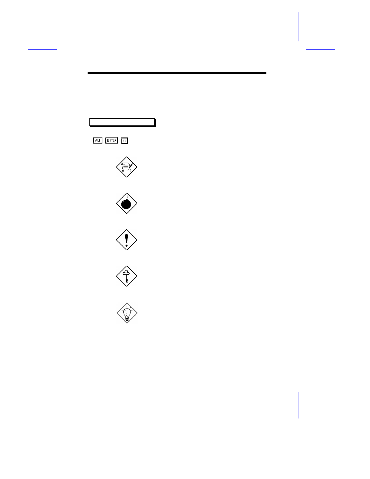
The following conventions are used in this manual:
Text entered by user
Represents text input by the user.
Screen messages
Denotes messages that appear
onscreen.
, , , etc. Represent the actual keys that you
have to press on the keyboard.
NOTE
Gives bits and pieces of additional
information related to the current
topic.
WARNING
Alerts you to any damage that might
result by not following the
instructions.
CAUTION
Gives precautionary measures to avoid
possible hardware or software
problems.
IMPORTANT
Reminds you to take specific actions
relevant to the accomplishment of
procedures.
TIP
Tells how to accomplish a procedure
with minimum steps through little
shortcuts.
Page 11

xi
Table of Contents
Chapter 1 System Board
1.1 Features .......................................................................... 1-1
1.2 Major Components .......................................................... 1-3
1.2.1 System Board Layout....................................... 1-4
1.3 Jumpers and Connectors ................................................. 1-5
1.3.1 Jumper and Connector Locations..................... 1-5
1.3.2 Jumper Settings............................................... 1-6
1.3.3 Connector Functions ....................................... 1-8
1.4 ESD Precautions ............................................................. 1-9
1.5 Installing the Processor Heat Sink and Fan ....................1-10
1.6 Installing a Pentium II Processor....................................1-13
1.7 Removing a Pentium II Processor...................................1-15
1.8 Memory Upgrade ...........................................................1-16
1.8.1 Memory Configurations .................................1-16
1.8.2 Installing a DIMM.........................................1-17
1.8.3 Removing a DIMM........................................1-18
1.8.4 Reconfiguring the System...............................1-19
1.9 VGA/LAN Combo Card (Optional) ................................1-20
1.9.1 Features .........................................................1-20
1.9.2 Card Layout ...................................................1-21
1.9.3 Jumper Settings..............................................1-22
1.9.4 Card Installation ............................................1-24
1.10 SCSI Feature..................................................................1-23
1.10.1 Using the SCSI Feature ..................................1-23
Page 12

xii
1.11 Server Management Features.........................................1-24
1.11.1 ASM Pro ........................................................1-24
1.11.2 Remote Diagnostic Management....................1-25
1.12 Error Messages..............................................................1-26
1.12.1 Software Error Messages ................................1-26
1.12.2 System Error Messages ..................................1-26
1.12.3 Correcting Error Conditions...........................1-29
Chapter 2 BIOS Utility
2.1 Entering Setup................................................................. 2-2
2.2 System Information..........................................................2-3
2.2.1 Processor .........................................................2-4
2.2.2 Processor Speed ............................................... 2-5
2.2.3 Bus Frequency .................................................2-5
2.2.4 Internal Cache .................................................2-5
2.2.5 External Cache ................................................2-5
2.2.6 Floppy Drive A................................................2-5
2.2.7 Floppy Drive B ................................................2-5
2.2.8 IDE Primary Channel Master...........................2-6
2.2.9 IDE Primary Channel Slave............................. 2-6
2.2.10 IDE Secondary Channel Master .......................2-6
2.2.11 IDE Secondary Channel Slave .........................2-6
2.2.12 Total Memory .................................................. 2-6
2.2.13 Serial Port 1..................................................... 2-7
2.2.14 Serial Port 2..................................................... 2-7
2.2.15 Parallel Port.....................................................2-7
Page 13

xiii
2.2.16 Pointing Device............................................... 2-7
2.2.17 Memory Parity Mode ....................................... 2-8
2.2.18 Onboard USB.................................................. 2-8
2.3 Product Information........................................................ 2-9
2.3.1 Product Name ................................................. 2-9
2.3.2 System S/N ..................................................... 2-9
2.3.3 Main Board ID...............................................2-10
2.3.4 Main Board S/N.............................................2-10
2.3.5 System BIOS Version.....................................2-10
2.3.6 System BIOS ID .............................................2-10
2.3.7 BIOS Release Date.........................................2-10
2.4 Disk Drives....................................................................2-11
2.4.1 Floppy Drives.................................................2-13
2.4.2 IDE Drives.....................................................2-13
2.5 Power Management........................................................2-17
2.5.1 Power Management Mode..............................2-17
2.5.2 Wakeup Event ................................................2-18
2.6 Startup Configuration ....................................................2-19
2.6.1 Fast POST Mode............................................2-19
2.6.2 Silent Boot.....................................................2-20
2.6.3 Num Lock After Boot.....................................2-20
2.6.4 Memory Test..................................................2-20
2.6.5 Initialize SCSI Before IDE.............................2-20
2.6.6 System Boot Drive..........................................2-21
2.6.7 Boot from CD-ROM.......................................2-21
2.6.8 Boot from Onboard SCSI Device....................2-21
Page 14

xiv
2.7 Advanced Configuration................................................ 2-22
2.7.1 Onboard Devices Configuration..................... 2-23
2.7.2 PnP/PCI System Configuration ......................2-29
2.7.3 Memory/Cache Configuration........................2-35
2.8 System Security Setup.................................................... 2-38
2.8.1 Disk Drive Control......................................... 2-38
2.8.2 Setup Password..............................................2-39
2.8.3 Power-on Password........................................2-43
2.9 Date and Time............................................................... 2-44
2.9.1 Date............................................................... 2-45
2.9.2 Time..............................................................2-45
2.10 Load Setup Default Settings ...........................................2-46
2.11 Abort Settings Change................................................... 2-46
2.12 Leaving Setup ................................................................2-47
Chapter 3 System Utilities
3.1 AFlash BIOS Utility ........................................................3-1
3.1.1 Executing AFlash ............................................3-2
3.1.2 Quick Way to Execute AFlash.......................... 3-3
3.2 SCSISelect Configuration Utility .....................................3-4
3.2.1 Overview .........................................................3-4
3.2.2 Utility Options.................................................3-6
3.2.3 Configuring Multiple SCSI Controllers ..........3-20
3.2.4 Disk Drives Over 1 GByte..............................3-21
Page 15

xv
List of Figures
1-1 System Board Layout....................................................... 1-4
1-2 Jumper and Connector Locations..................................... 1-5
1-3 Matching the Fan-Heat Sink Clips with the Holes on
the Processor ..................................................................1-10
1-4 Inserting the Clip Ends to the Processor Holes................1-11
1-5 Locking a Wide Clip End...............................................1-12
1-6 Locking a Narrow Clip End............................................1-12
1-7 Installing the Pentium II Retention Mechanism..............1-13
1-8 Installing a Pentium II Processor....................................1-14
1-9 Securing the Pentium II Processor..................................1-14
1-10 Unlocking the Module Latches.......................................1-15
1-11 Removing the Pentium II Processor................................1-15
1-12 Installing a DIMM.........................................................1-17
1-13 Removing a DIMM........................................................1-18
1-14 VGA/LAN Combo Card Layout .....................................1-21
1-15 Installing the VGA/LAN Combo Card ...........................1-24
1-16 Installing the RDM Module............................................1-25
3-1 Options Menu Screen...................................................... 3-6
3-2 Configure/View Host Adapter Settings Screen................. 3-7
3-3 Host Adapter SCSI ID Selections..................................... 3-8
3-4 SCSI Parity Checking Selections..................................... 3-9
3-5 Host Adapter SCSI Termination.....................................3-10
3-6 Boot Device Configuration.............................................3-11
Page 16

xvi
3-7 SCSI Device Configuration............................................3-12
3-8 Advanced Configuration Options................................... 3-15
3-9 SCSI Disk Utilities Screen .............................................3-18
List of Tables
1-1 Jumper Settings................................................................1-6
1-2 JP5 Settings for CPU Core/Bus Frequency Ratio ..............1-7
1-3 Connector Functions........................................................1-8
1-4 Memory Configurations .................................................1-16
1-5 VGA/LAN Combo Card Jumper Settings.......................1-22
1-6 VGA/LAN Combo Card Connector Functions................1-23
1-7 VGA/LAN Combo Card LED Functions........................ 1-23
2-1 Parallel Port Operation Mode Settings............................ 2-27
2-2 Drive Control Settings ................................................... 2-39
3-1 Settings for the SCSI Controller and All Devices .............3-4
3-2 Individual Settings for SCSI Drives..................................3-5
 Loading...