

Page 1
System Board
System Board 1-1
1.1 Features
This high-perf ormance system board is designed to support the Intel
P54C and P55C CPUs running at 75/100/120/133/150/ 166/200 MHz.
It utilizes both the EISA and the PCI local bus architecture. Three
EISA and four PCI bus slots reside on the board to al low installat ion
of either master or slave devices, except for one PCI slot that
supports only slave devices.
The board has three memory banks composed of t wo 72-pin SIMM
sockets each that support a maximum system memory of 192 MB
using 32-MB SIMMs. The SIMM sockets support both EDO and fastpage mode SIMMs. A second-level cache socket is avail able for a
256-KB or 512-KB synchronous SRAM module.
A 50-pin Fast SCSI-II int erface with 10 MB/s transfer rate and a 68pin W ide SCSI interf ace that transfer s at 20 MB/ s (Wide SCSI ) and
40 MB/s (Ultra SCSI) com e with the system board to connect SCSI
devi ces. Standard I/O features such as two serial interfaces (COM1,
COM2), one paral lel port interf ace, an IDE dri ve i nterfac e, a diskett e
driv e interf ace, and PS/2 mouse and keyboard c onnectors reside on
the system board.
The system board supports two optional f eatures, the ASM Pro and
the Remote Diagnostic Management (RDM) for better server
management. These features maximize the system operating time
by minimiz ing the downtime.
Page 2

1-2 User’s Guide
1.2 Major Components
The system board has the following major components:
•
One zero-insertion force (ZIF) socket for Intel P54C or P55C
CPU
•
Three mem ory banks (Bank 1 to Bank 3) com posed of six 72- pin
SIMM sockets
•
Synchronous cache module socket that supports 256 KB and
512 KB second-level cache
•
Three EISA and four PCI expansion slots
•
256-KB Flash ROM for system BIOS
•
RTC chip that contains clock/calendar plus 128 bytes CMOS
RAM with battery backup
•
50-pin Fast SCSI-II and 68-pi n Wide SCSI interfaces
•
Two 24-pin RDM int er faces
•
IDE hard disk and di sket te drive interfaces
•
Onboard VRAM pl us a VRAM socket for video memory upgr ade
•
Power connector f or 200- watt switc hing power supply
•
I/O, SCSI, VGA, memory, and ASM Pro controller chipsets
•
External ports:
• PS/2-compatible k ey boar d por t
• PS/2-compatible mouse port
Page 3
System Board 1-3
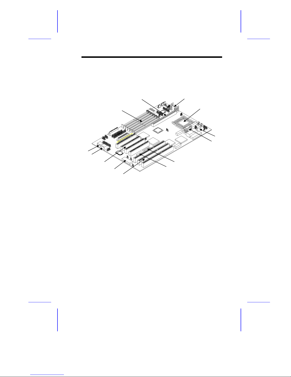
1.2.1 System Board Layout
1 PS/2 keyboard connector
2 PS/2 mouse connector
3 PCI slots
4 Keyboard controller
5 EISA slots
6 Video RAM
7 Video RAM upgrade socket
8 CPU voltage regulator
9 Buzzer
10 CPU socket
11 CPU voltage regulator
12 Cache module socket
13 SIMM sockets
Figure 1-1 System Board Layout
1
2
4
3
5
6
7
9
13
10
8
11
12
Page 4
1-4 User’s Guide
1.3 Jumpers and Connectors
1.3.1 Jumper and Connector Locations
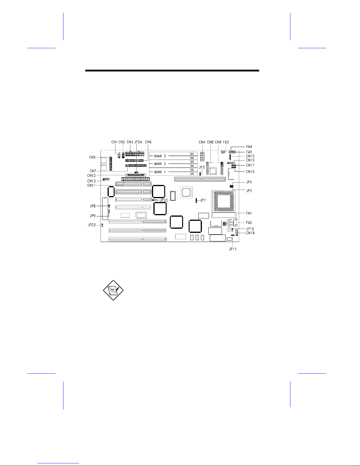
Figure 1-2 shows the jumper locations on the system board. The
blackened pin on a jumper represents pi n 1.
Figure 1-2 Jumper Locat ions
Jumpers are prefixed “JP”. Connectors are
prefixed “CN”. FA1 to FA5 are fan
connectors.
The blackened pin of a jumper r epr es ents
pin 1.
Page 5
System Board 1-5
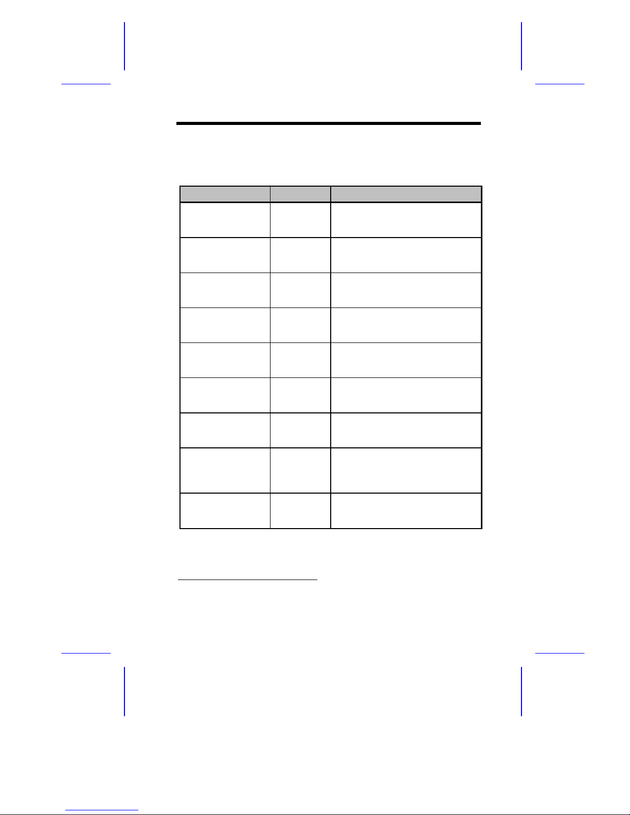
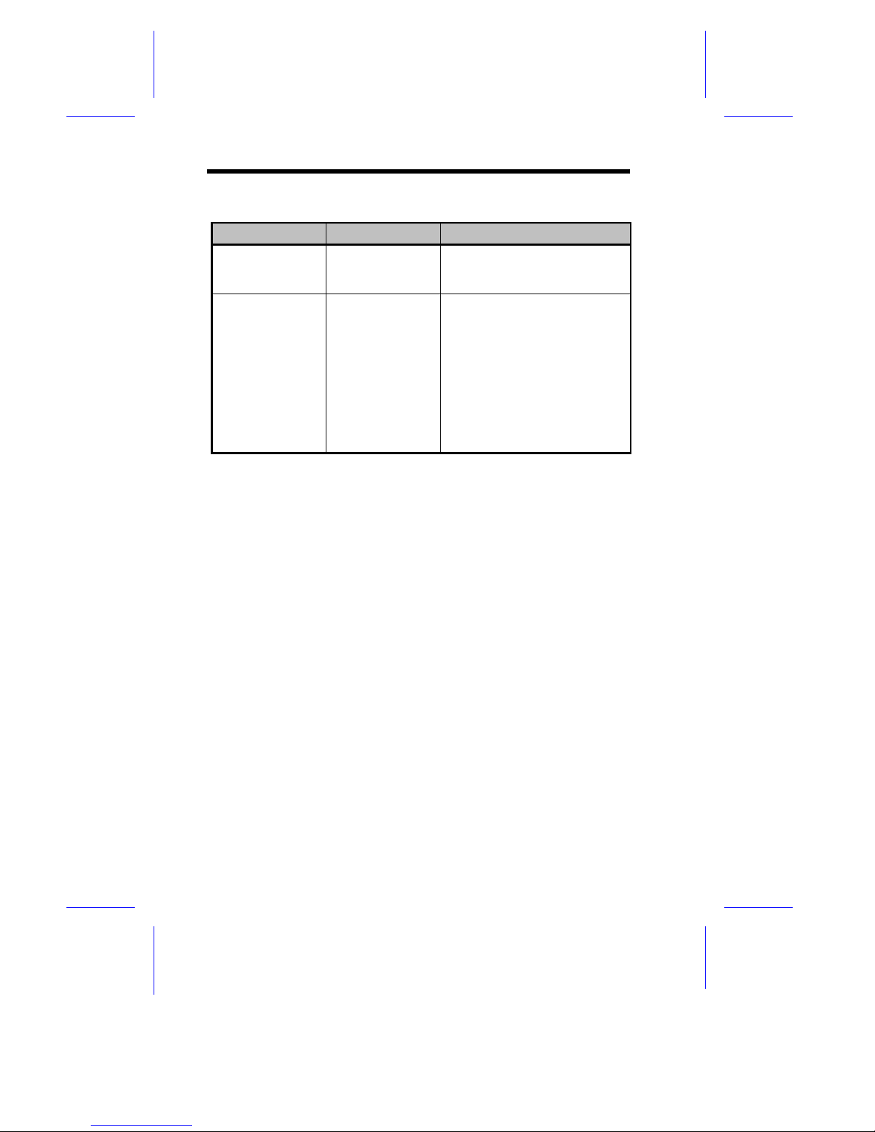
1.3.2 Jumper Settings
Table 1-1 Jumper Settings
Jumper Setting Function
CPU Voltage
JP1 1-2
2-3
*
VR
VRE
Cache Size
JP3 1-2*
2-3
256 KB
512 KB
BIOS Version
JP8 1-2*
2-3
Acer
Generic
Password Security
JP9 1-2
2-3*
Enabled
Bypass
PC Sound Source
JP10 1-2*
2-3
Buzzer
Speaker
Front Panel Reset
JP11 1-2*
2-3
Enabled
Disabled
CPU Type
JP17, JP18, JP19 1-2
2-3*
P55C CPU
P54C CPU
SCSI Selection
JP20 1-2*
2-3
4-5
PCI device ID is 11 Hex
PCI device ID is 0C Hex
Disabled
Onboard VGA
JP23 1-2*
2-3
Enabled
Disabled
*
Default setting
Page 6
1-6 User’s Guide
Table 1-1 Jumper Settings ( c ontinued)
Jumper Setting Function
SCSI Termi na t ion
JP24 1-2*
2-3
High-byte terminat or O N
High-byte terminat or O FF
Core/Bus Freq.
JP4, JP5, JP7
JP4 JP5 JP7
2-3 2-3 1-2
1-2 1-2 2-3
2-3 1-2 2-3
2-3 2-3 2-3
1-2 2-3 3-4
1-2 1-2 3-4
2-3 1-2 3-4
2-3 2-3 3-4
Bus Freq. Core Freq. Ratio
50 MHz 75 MHz 3/2
60 MHz 150 MHz 5/2
60 MHz 120 MHz 2/1
60 MHz 90 MHz 3/2
66 MHz 200 MHz 3/1
66 MHz 166 MHz 5/2
66 MHz 133 MHz 2/1
66 MHz 100 MHz 3/2
Page 7
System Board 1-7
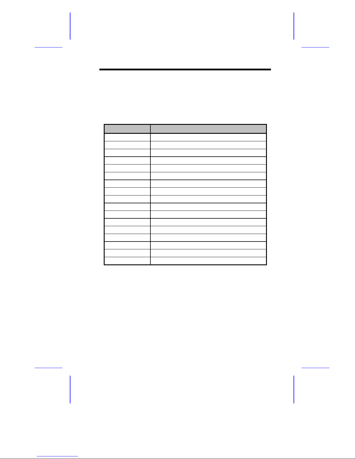
1.3.3 Connector Functions
Table 1-2 l ists the dif f erent connec tors on the system boar d and their
respective functions.
Table 1-2 Connector Funct ions
Connector Function
CN1 COM1
CN2 COM2
CN3 Power connector for 200- watt SPS
CN4 Power connector for 300- watt SPS
CN5 Parallel port connector
CN6 Diskette drive connector
CN7 IDE drives connector
CN8 Remote diagnostic module (RDM) connector
CN9 Remote diagnostic module (RDM) connector
CN10 Faulty-drive LED connector
CN11 Fast SCSI-II (narrow SCSI) connector
CN12 Wide SCSI connector
CN13 VGA daughter board connector
CN15 Power LED and keylock connector
CN16 Hard disk LED connector
CN17 Speaker connector
CN18 Reset/Turbo connector
Page 8

1-8 User’s Guide
1.4 ESD Precautions
Always observe the following ESD (electrostatic discharge)
precautions before installing any system c omponent:
1. Do not remove any system com ponent from i t s packaging unl ess
you are ready to i nstall it .
2. Wear a wrist grounding strap before handling electronic
components. Wrist grounding straps are available at most
electronic component stor es.
DO NOT attempt the procedur es in the
following sect ions unles s y ou ar e c onfident of
your capability to per form them. Otherwise,
ask a service tec hnic ian for assistance.
Page 9
System Board 1-9
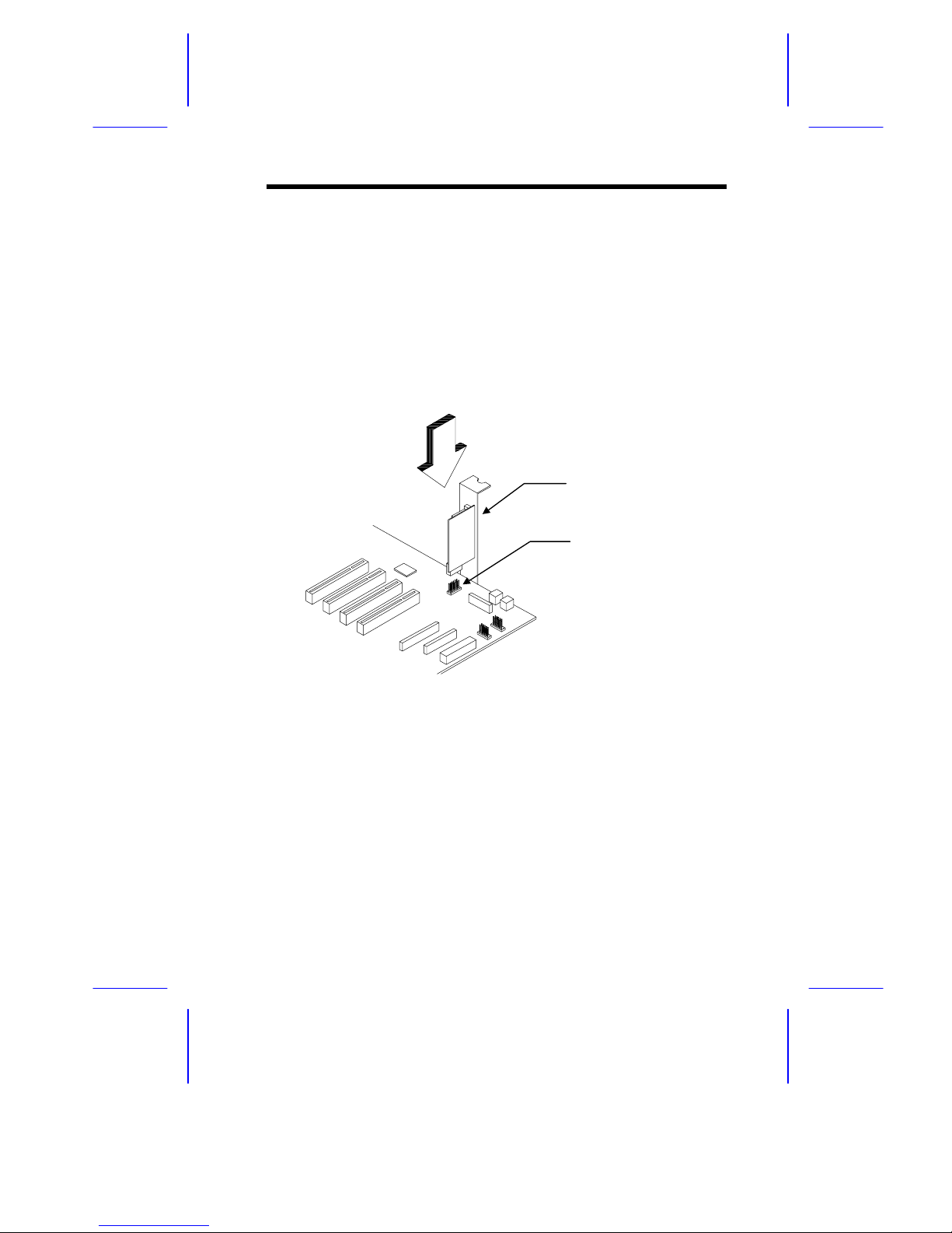
1.5 Installing a VGA Daughter Board
The system board com es with a video c ontroller, a video connector,
and a VGA daughter board. These com ponents save you t he troubl e
of buyi ng a v ideo board and sav e one bus slot f or anot her ex pansion
board. The daughter boar d c ar r ies an external vi deo por t.
To install, simply plug-in the daughter board into CN13 and secure
the bracket wit h a screw.
Figure 1-4 Installing a VGA Daughter Board
External VGA Port
VGA Connector
(CN13)
Page 10
1-10 User’s Guide
1.6 CPU Upgrade
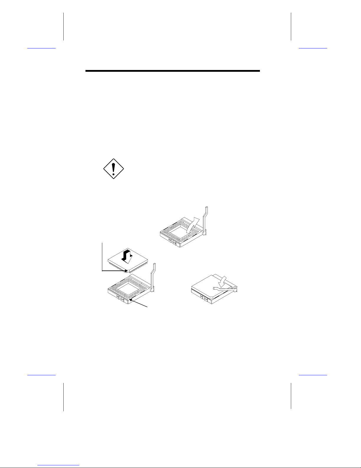
The system board comes with a zero-insertion forc e (ZIF) CPU socket
for easy installati on.
Follow these steps to install a Pentium CPU:
1. Pull up t he socket lever.
2. Insert the CPU, m aking sure that the pin 1 of the CPU connects
to pin 1 of the socket.
Be careful not t o bend any pins .
3. Pull down the socket lever .
Figure 1-5 Installing a Pentium CP U
STEP 1
STEP 2
STEP 3
Notched Corner
Pin 1 Indicator
Page 11
System Board 1-11
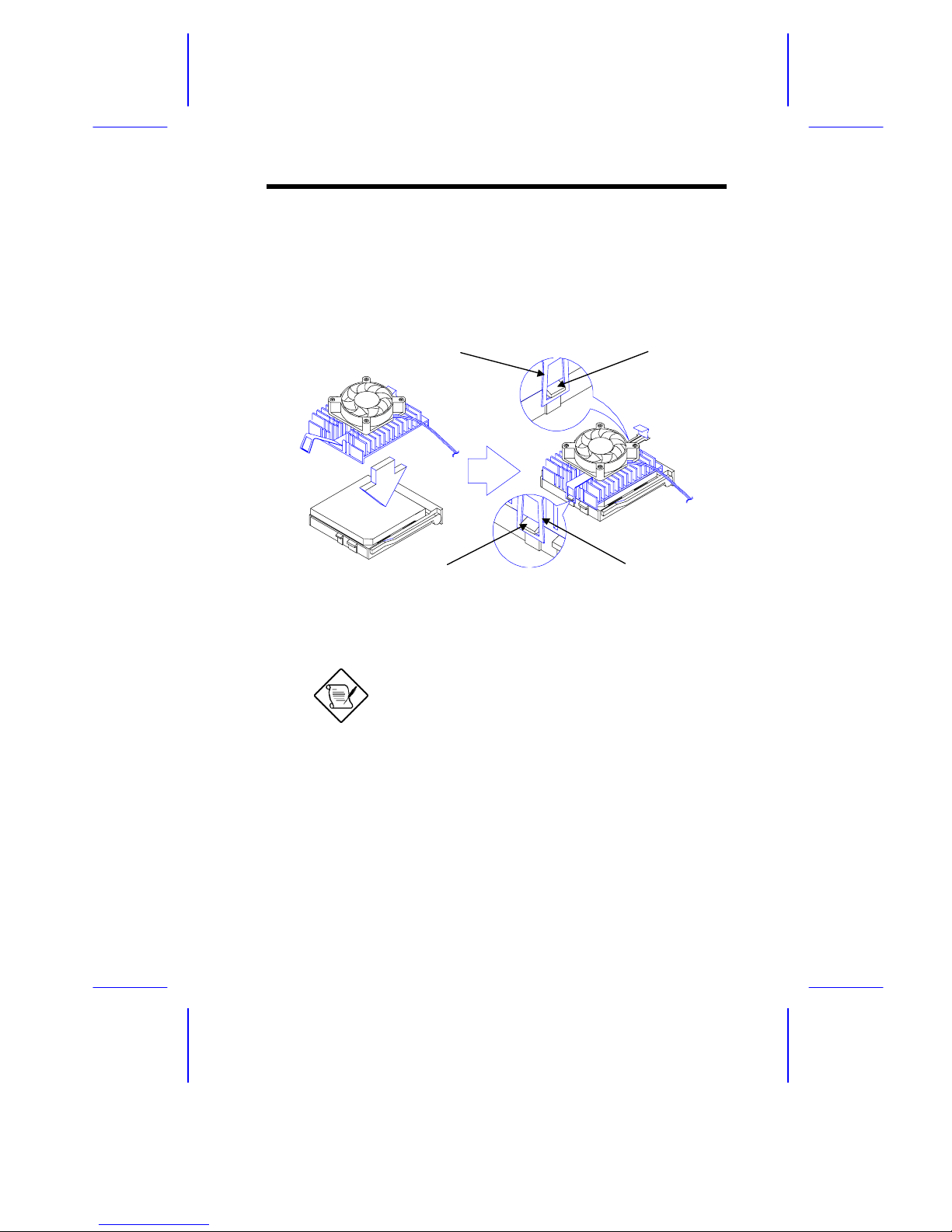
4. Place the CPU heat sink and fan over the CP U.
5. Link the front heat sink hook t o the holdi ng tab on the f ront edge
of the CPU socket, then the rear hook to t he rear holding tab.
This locks the heat sink and fan t o the CPU socket.
Figure 1-6 Installing the CPU Heat Sink and Fan
To remove the heat s ink and fan, simply
press the upper part of the rear hook inw ar d.
6. Attach the CP U fan cables to t he c onnec tors on the board.
7. Change the settings of jumper JP1 f or the correct CPU v oltage
and jumpers JP4, JP5, and JP7 f or the CPU frequency. Refer to
Table 1-1 for the jumper settings.
Holding Tab (rear)Heat Sink Hook (rear)
Heat Sink Hook (front)
Holding Tab (front)
Page 12

1-12 User’s Guide
1.7 Memory Upgrade
The six 72-pin SIMM sockets onboard support both Extended Data
Output (EDO) and fast-page mode SIMMs. You m ay install 4-MB and
16-MB single-density as well as 8-MB, and 32-MB double-density
SIMMs for a total of 192-MB system memory. The SIMM sockets
also support 64-MB SIMMs, when available, to achieve 384-MB
syste m mem ory.
1.7.1 Rules for Adding Memory
•
Use only the same ty pe of SIMM in a given bank
•
You may combine different types of SIMMs for a particular
memor y conf igurati on as long as the SIM Ms in each bank are of
the same type.
•
Always install SIMMs in pairs. For example, for a total memory
of 16 MB, install two 8-MB SIMMs into the sockets marked SI6
and SI5 (bank 1) or SI2 and SI1 (bank 3). You can not use a
16-MB SIMM alone for a 16-MB memory.
•
Always
install
SIMMs starting from an inner socket. For
exampl e, instal l SIMMs in socket SI6 befor e in socket SI5, or i n
socket SI2 before socket SI1.
•
Always
remove
SIMMs starting from an outer socket. For
example, remove SI M M s i n socket SI5 bef or e in socket SI6, or in
socket SI1 before socket SI2.
Page 13
System Board 1-13
1.7.2 Memory Configurations
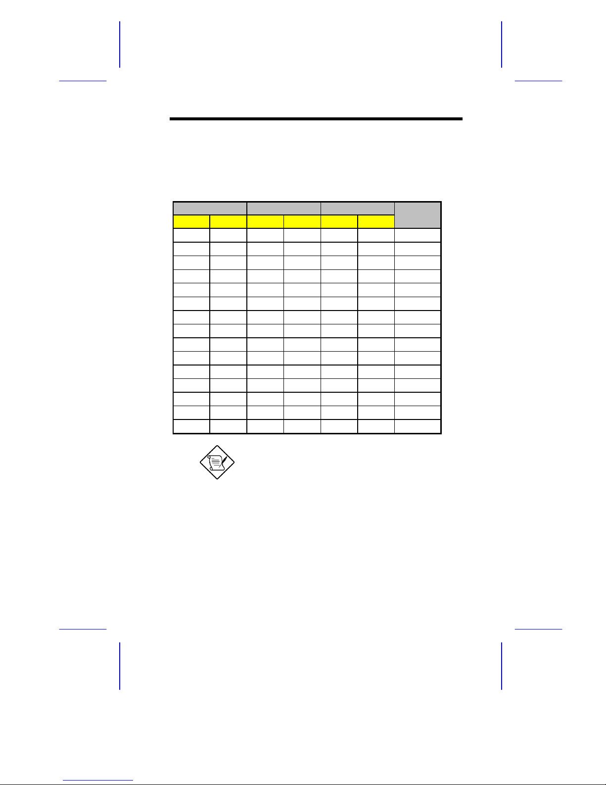
Table 1-3 l ists the available memory c onfigurations.
Table 1-3 Memory Configurat ions
Bank 1 Bank 2 Bank 3 Total
SI1 SI5 SI4 SI3 SI2 SI1 Memory
4 MB 4 MB 8 MB
8 MB 8 MB 16 MB
8 MB 8 MB 4 MB 4 MB 24 MB
8 MB 8 MB 8 MB 8 MB 32 MB
16 MB 16 MB 32 MB
16 MB 16 MB 4 MB 4 MB 40 MB
16 MB 16 MB 8 MB 8 MB 48 MB
16 MB 16 MB 8 MB 8 MB 4 MB 4 MB 56 MB
8 MB 8 MB 8 MB 8 MB 16 MB 16 MB 64 MB
4 MB 4 MB 8 MB 8 MB 32 MB 32 MB 88 MB
16 MB 16 MB 16 MB 16 MB 16 MB 16 MB 96 MB
32 MB 32 MB 8 MB 8 MB 16 MB 16 MB 112 MB
32 MB 32 MB 32 MB 32 MB 128 MB
32 MB 32 MB 32 MB 32 MB 16 MB 16 MB 160 MB
32 MB 32 MB 32 MB 32 MB 32 MB 32 MB 192 MB
The above configurat ions ar e only s om e of
the available memory com binations. You
can use other combinat ions as long as y ou
follow the rules for upgrading memory. S ee
section 1.7.1.
Page 14
1-14 User’s Guide
1.7.3 Installing a SIMM
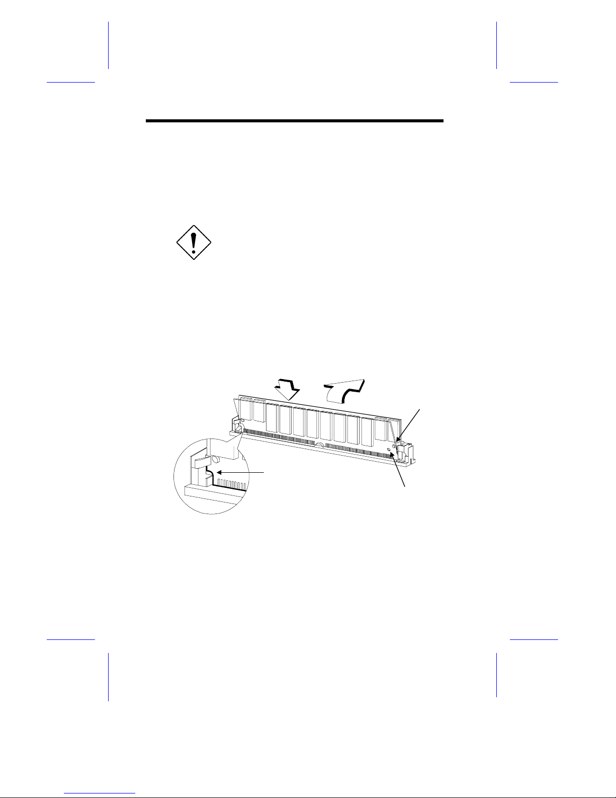
Follow these steps to install a SIMM :
1. Careful ly slip a SIMM at a 45° angle into a socket m aking sure
that the curv ed edge indicati ng the pin 1 of the SIMM m atches
pin 1 of the socket.
A SIMM fits only in one dir ec tion. If you slip
in a SIMM but would not c om pletely fit, y ou
may have inserted it the wrong way .
Reverse the orientation of the SIMM.
2. Gently push the S IMM to a v er tical posit ion until t he pegs of t he
socket slip into t he hol es on the SIM M, and t he hol ding c li ps loc k
the SIMM into position. The SIMM should be at a 90° angle
when installed.
Figure 1-7 Installing a SIMM
Hole
Peg
Pin 1 Indicator
(curved edge)
1
2
Page 15
System Board 1-15
1.7.4 Removing a SIMM
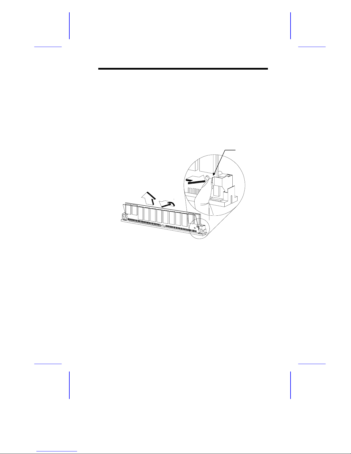
Follow these steps to remove a SIMM:
1. Press the holding clips on both sides of the SIMM outward to
release it.
2. Push the SIMM downward to a 45
o
angle.
3. Pull t he S IMM out of the socket.
Figure 1-8 Removing a SIMM
1
2
3
Holding Clip
Page 16

1-16 User’s Guide
1.7.5 Reconfiguring the System
Reconfi gur e the system after installing or remov ing SIMMs.
Follow these steps to reconfigure the system:
1. Reboot the system. A memory error message appears,
indicat ing t hat t he tot al m em ory does not m atc h t he val ue stor ed
in CMOS.
2. Press
+ + duri ng the power-on self-test (POST)
routine to run Setup. During POST, a message indicating a
wrong memory c onfigurat ion appears.
3. Press
twice to exit Setup and reboot the system. The
system boots with the new memory configuration.
If you operate the system with WindowsNT,
NetWare, or Unix Ware, make sure to run
ECU every time you ins tall or remove an
EISA or a non-PnP ISA car d. See Chapter 3
for informat ion on E CU.
Page 17
System Board 1-17
1.8 Second-level Cache Upgrade
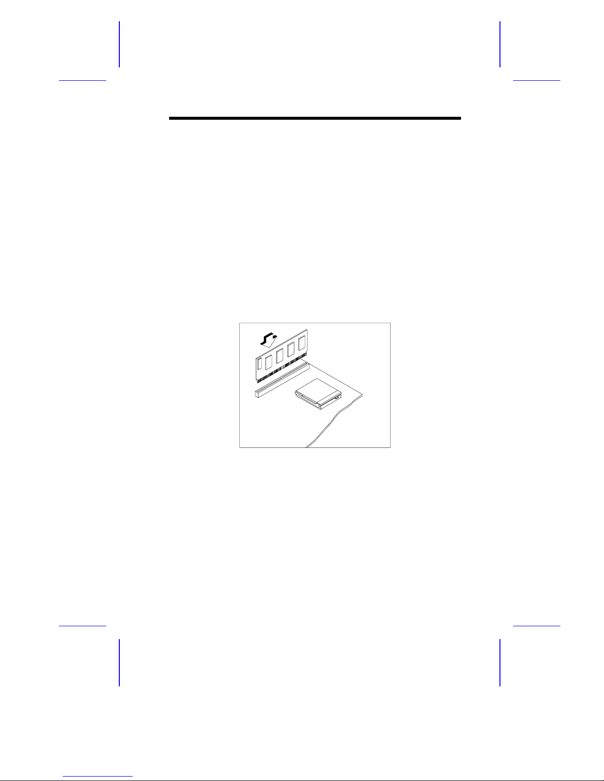
The system supports synchronous pipel ine burst second-level cache.
The system board has an exclusive 160-pin socket for the
synchronous pipeline bur st cache modul e. The c ache modul e socket
supports either a 256 KB or 512 K B 3.3V cache module.
Follow these steps to install a cache module:
1. Position the cache module on top of the socket such that its
component side faces the CPU.
2. Insert the cache m odule carefully until the golden fi nger of the
module fit into place.
Figure 1-9 Installing a Synchr onous Cac he M odule
Page 18
1-18 User’s Guide
1.9 Video Memory Upgrade
Larger video memory allows you to display higher resolutions and
more colors. The system board com es with a 512-KB v ideo mem ory
onboard upgradable to 1 MB .
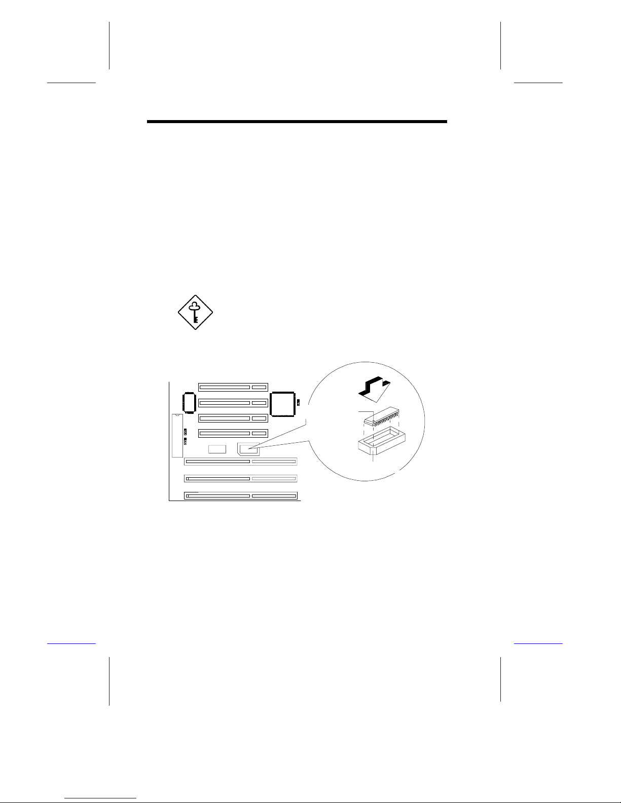
Follow these steps to upgrade the video memory :
1. Locate the video DRAM upgrade socket labeled U44 on the
system board. See F igure 1-1.
2. Gently insert a 514260ASL (256K x 16, 70ns SOJ) chip into t he
upgrade socket.
Make sure that the pin 1 indicator on the chip
matches the not c hed c or ner of the socket.
Figure 1-10 Installing a Video Mem or y Chip
Pin 1 Indicator
Notched Corner
Page 19

System Board 1-19
1.10 SCSI Feature
The system board feat ures a single-chi p SCSI host adapt er that adds
SCSI I/O capability to the system. The chipset consists of an onboard
micr ocontrol ler, bus master i nterf ace cont roll er, and SCSI control lers.
A 50-pin Fast SCSI-II interface with 10 MB/s transfer rate and a
68-pin Wide SCSI interface that transfers at 20 MB/s (Wide SCSI)
and 40 MB/s (Ul tra SCSI) ar e also onboard t o accomm odate v arious
SCSI devices.
1.10.1 Using the SCSI Feature
Follow these steps to use the SCSI feature:
1. Install a S CSI device i n the system and connect it t o the SCSI
interface on the system board. See Figure 1- 1 for the location.
2. Set jumper JP20 and JP24 accordingl y. Refer to Tabl e 1-1 for
the jum per settings.
3. Enter the BIOS utility to set the corresponding SCSI parameters.
4. Enter the SCSI Setup utility and make the necessary changes.
Refer to the SCSI manual for more information.
For more inf orm at ion about the i nstal l ati on procedur es under dif ferent
operating system s, read the README.XXX i n th e subdirect ory of the
target operating system.
Page 20

1-20 User’s Guide
1.11 Server Management Features
1.11.1 Remote Diagnostic Management
The Remote Diagnostic Management (RDM) is a network
management tool t hat utilizes modems and telephone li nes to cont rol
a host of serv ers f rom a r em ote stat ion. It m oni tor s and analy zes t he
server condi tion, updates the BIO S settings if necessary, or reboots
the server in the event of failure and quickly return it to normal
operation. This capability to execute the RDM program from a
remote sit e bridges the di stance barri er in f ix ing serv er probl em s and
reduces wasted time due to system fai lure.
Refer to the RDM user’s manual for more information.
1.11.2 ASM Pro
The ASM Pro is a server management tool based on the Simple
Network Management Protocol (SNMP). It detects server problems
related to t he CPU thermal c ondition, 5V/3.3V detect ion, or PCI bus
utilization calculation.
This feature is designed primarily for server supervisors and
management i nf orm at ion system (MIS ) personnel t o hel p t hem det ect
errors or potential trouble spots in their network servers through a
single management stati on.
The ASM Pro consists of two major parts:
•
ASM-Station - a Windows-based monitoring station that
communicates with the ASM-Agents.
•
ASM-Agent(s) - the individual servers managed by the
ASM-Station.
Refer to the ASM Pro user’s manual for more i nformation.
Page 21

System Board 1-21
1.12 Error Messages
Do not continue usi ng the computer if you receiv e an error m essage
of any type. Note the message and take corrective action. This
section describes the types of error messages and lists their
corresponding corrective measures.
There are two general t y pes of error messages:
•
Software
•
System
1.12.1 Software Error Messages
Software error messages are returned by your operating system or
application. These messages typically occur after you boot the
operating system or when you run your application. If you receiv e
this type of message, consult your application or operating system
manual for help.
1.12.2 System Error Messages
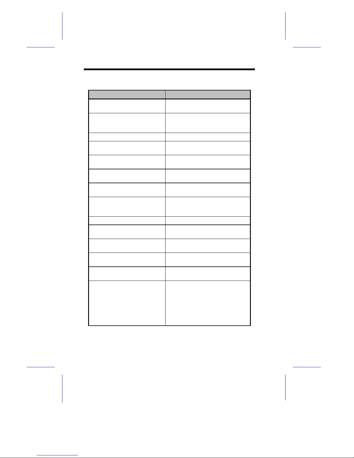
A system error message indicates a problem with the com puter i tself .
A message of this type normally appears during the power-on selftest, before the operati ng system prompt appears. Table 1- 4 li sts the
system error messages.
Page 22
1-22 User’s Guide
Table 1-4 System Error Messages
Message Action
CMOS Battery Error Replace the RTC chip or contact
your dealer.
CMOS Checksum Error Check the RTC chip and the
necessary jumper. If the battery
is still good, run Setup.
Display Card Mismatch Run Setup
Diskette Drive Controller Error
or Not Installed
Check and connect the control
cable to the diskette controller.
Diskette Drive Error Diskette may be defective. If not,
replace the diskette drive.
Diskette Drive A Type
Mismatch
Run Setup and select the proper
drive type.
Diskette Drive B Type
Mismatch
Run Setup and select the proper
drive type.
Equipment Configurat ion
Error
Modify DRAM configuration to
agree with one of the options in
Table 1-3.
Hard Disk Controller Error Run Setup.
Hard Disk 0 Error Check all cable connections.
Replace hard disk.
Hard Disk 1 Error Check all cable connections.
Replace hard disk.
Keyboard Error or No
Keyboard Connected
Check and connect the keyboard
to the system unit.
Keyboard Interface Error Replace the keyboard or contact
your dealer.
Memory Error at:
MMMM:SSSS:OOO
(W :XXXX, R:YYYY)
where:
M: MB, S: Segment,
O: Offset,
X/Y: write/read pattern
Check SIMMs on the system
board. Contact your dealer.
Page 23
System Board 1-23
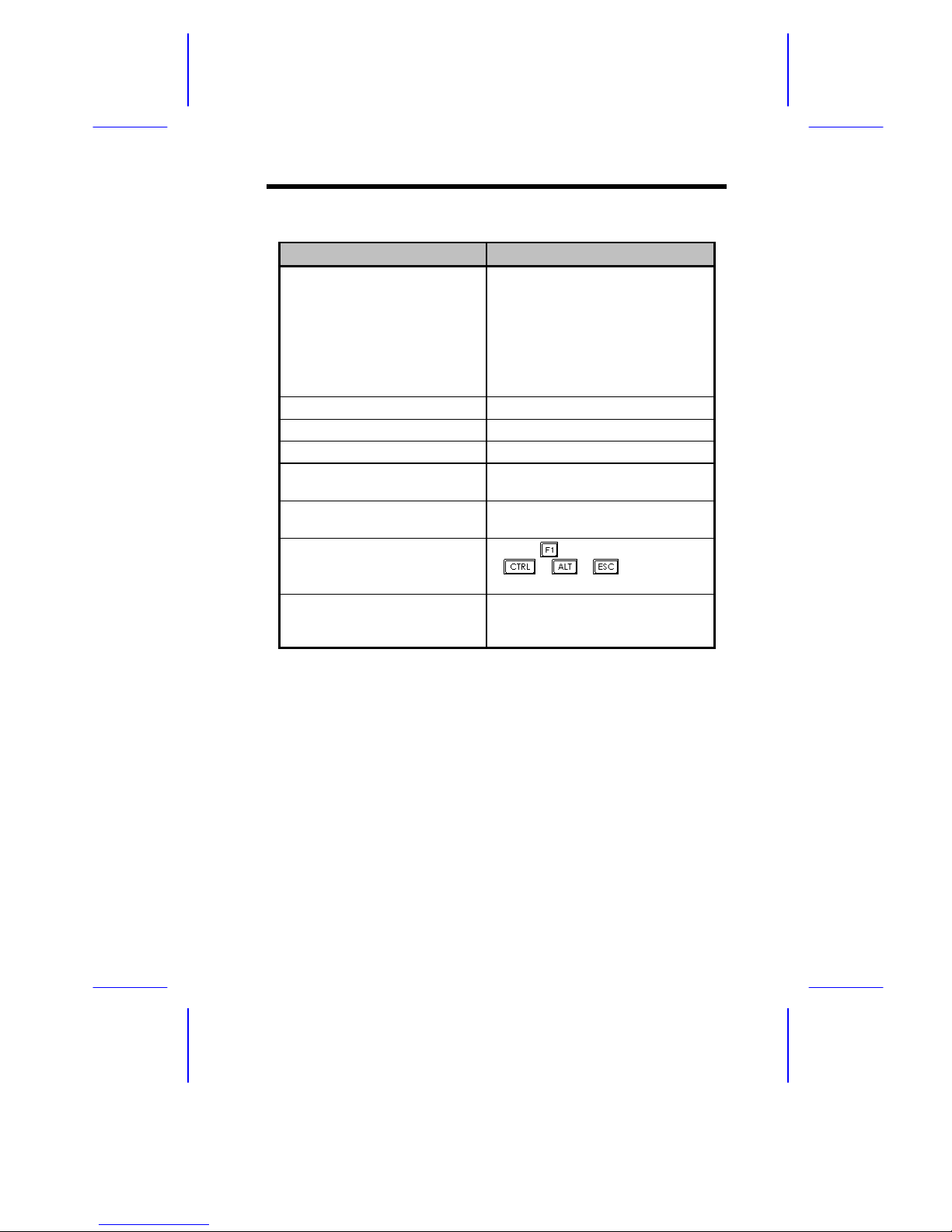
Table 1-4 System Error Messages (continued)
Message Action
Memor y S ize Mismatch
CPU Clock Mismatch
Check the memory size based on
the system specifications. Check
the internal cable connections. If
you are sure that connections
and values are correct, ignore the
message. If the message
reappears, ask for technical
assistance.
Onboard Serial Port 1 Confl ict Run Setup and disable the port.
Onboard Serial Port 2 Confl ict Run Setup and disable the port.
Onboard Parallel Port Conflict Run Setup and disabl e the port.
Pointing Device Error Check and connect pointing
device.
Pointing Device Interface
Error
Replace the pointing device or
contact your dealer.
Press F1 key to continue or
Ctrl-Alt-Esc for Setup
Press
or
+ + to enter
Setup.
Real Time Clock Error Check the RTC chip. If it is still
good, run Setup. If not, replace
the RTC chip.
Page 24

1-24 User’s Guide
1.12.3 Correcting Error Conditions
As a general rule, if an error m essage says "Press F1 to conti nue," it
is caused by a confi guration probl em, which can be easily corrected.
An equipment malfuncti on is more likely t o cause a fatal error, i.e., an
error that causes com plete system failur e.
Here are some corrective measures for er r or c onditions:
1. Run Setup. You m ust know the correct configur ation v alues f or
your system before you enter Setup, which is why you should
write them down when the system is correctly configured. An
incorrect configuration is a major cause of power-on error
messages, especially for a new system.
2. Remove the system cover, following the directions in the housi ng
install ation manual. Check that the jumper s on the system board
and any expansion boards are set corr ec tly.
3. If you cannot access a new disk, it m ay be because your disk is
not properly f ormatted. Format the disk first using the FDISK
and FORMAT c ommands.
4. Check that al l connectors and boards are secure.
If you go t hrough these steps and still receive an error message, the
cause may be an equipment malfunct ion.
If you are sure that your configuration values are correct and your
battery is in good condition, the problem may lie in a damaged or
defective c hip.
In either c ase, c ontact an authori z ed servic e c enter for assistance.
 Loading...