

Page 1

TravelMate™ 7100 Series
Notebook Computer
User’s Guide
Page 2

Copyright
This is a product of Acer Inc. developed to TI specifications.
Acer and the Acer logo are registered trademarks and
TravelMate is a trademark of Acer Inc. Texas Instruments,
TI and the TI logo are registered trademarks of Texas
Instruments Inc. Microsoft, Windows, and the Windows logo
are registered trademarks of Microsoft Corporation. Intel
and Pentium are registered trademarks of Intel Corporation.
All other brands/product names are trademarks or
registered trademarks of their respective companies.
No part of this publication may be reproduced, transmitted,
transcribed, stored in a retrieval system, or translated into
any language or computer language, in any form or by any
means, electronic, mechanical, magnetic, optical, chemical,
manual or otherwise, without the prior written permission
of this company.
© 1997 by this company. All rights reserved.
Disclaimer of Warranties
ii
This company makes no representations or warranties,
either expressed or implied, with respect to the contents
hereof and specifically disclaims the implied warranties of
merchantability or fitness for a particular purpose. Any
software described in this manual is sold or licensed “as is.”
Should the programs prove defective following their
purchase, the buyer (and not this company, its distributor,
or its dealer) assumes the entire cost of all necessary
servicing, repair, and any incidental or consequential
damages resulting from any defect in the software. Further,
this company reserves the right to revise this publication
and to make changes from time to time in the contents
hereof without obligation to notify any person of such
revision or changes.
Page 3

About This User’s Guide
The following conventions are used in this manual:
Notes related to the current topic
Warnings about actions that can cause
damage.
Cautions that help you avoid problems
Important reminders.
Tips or shortcuts.
iii
Page 4

iv
Page 5

Contents
Getting Started............................................................ 1
Unpacking Your Computer...........................1
Taking Care of Your Computer .....................2
Cleaning............................................... 3
AC Adapter........................................... 3
Battery Pack.........................................4
Powering Up Your Computer ........................5
Entering User Information.....................6
Creating Backup and Startup Diskettes .. 6
Using Diskettes............................................7
Travel Tips ................................................... 8
Getting Help...............................................10
Technical Support...............................10
World Wide Web..................................10
System Tour................................................................ 11
Feature Summary ......................................11
Performance .......................................11
Multimedia and Communications ....... 12
Ergonomics......................................... 12
Expandability .....................................12
Display ......................................................14
Opening and Closing the Display ........ 14
FlashStart Automatic Power-On..........14
Indicator Lights...................................15
Keyboard....................................................17
Lock Keys ...........................................18
Embedded Keypad ..............................20
Windows 95 Keys................................ 22
Hot Keys.............................................23
Touchpad............................................28
Automatic Tilt.....................................31
Palm Rest ...........................................33
v
Page 6

Contents
Storage ...................................................... 34
Audio.........................................................40
Ports..........................................................42
Security .....................................................48
Power ......................................................................... 42
Battery Pack .............................................. 49
Advanced Power Management .................... 59
Heuristic Power Management..................... 60
Hard Disk...........................................34
Module Bay.........................................34
Ejecting a CD......................................35
Using the Floppy Drive Module
Externally.........................................35
Swapping Modules.............................. 38
Audio Control ..................................... 41
Rear Panel Ports .................................42
Left Panel Ports................................... 45
System Resource Lock ........................48
Removing and Installing the
Battery Pack.................................... 50
Charging the Battery........................... 51
Checking the Battery Level.................. 53
Optimizing Battery Life ....................... 55
Low-Battery Warning.......................... 56
Suspend to Disk .................................61
Suspend to Memory............................62
vi
Peripherals and Options........................................... 56
Printers...................................................... 64
PC Cards.................................................... 65
Audio Devices ............................................67
External Monitor........................................68
External Keyboard...................................... 69
External Keypad.........................................70
External Pointing Device ............................71
Page 7

Contents
Mini Dock ..................................................73
Floppy Drive Cable.....................................75
PS/2 Y-Bridge Cable .................................. 76
File Transfer Cable..................................... 77
Battery Pack .............................................. 78
AC Adapter ................................................78
Memory Upgrades ......................................79
Hard Disk Upgrades................................... 82
System Utilities........................................................... 76
Sleep Manager ...........................................85
Accessing Sleep Manager ....................86
Creating Reserved Space..................... 88
Removing a Reserved Space................ 90
Minimizing Sleep Manager ..................91
Exiting Sleep Manager ........................ 92
Sleep Manager Troubleshooting Tips ...92
Uninstalling Sleep Manager ................93
Touchpad Driver ........................................ 95
BIOS Setup Utility...................................... 96
About My Computer............................ 97
System Configuration .........................99
Advanced System Configuration........ 102
Power Saving Options ....................... 108
System Security................................ 110
Reset To Default Settings.................. 116
Appendix................................................................. 104
Troubleshooting ....................................... 117
Startup Error Messages............................ 125
Specifications........................................... 127
System Memory Map................................132
I/O Address Map...................................... 132
Interrupts ................................................ 133
DMA Channels.........................................134
IMPORTANT SAFETY INSTRUCTIONS .......135
vii
Page 8

Contents
Canadian DOC Notice .............................. 137
FCC Class B Radio Frequency
Interference Statement.......................... 138
Index ........................................................................ 123
viii
Page 9

Getting Started
Congratulations on your purchase of the
TravelMate 7100 series notebook computer.
Guaranteed and backed by world-class support,
you can be sure of top-notch performance from
your new computer. This section guides you
through the first few steps in setting up your
computer.
Unpacking Your Computer
Carefully unpack the carton and remove the
contents. You should find your computer and an
accessory box containing the following items:
q AC adapter
1
q Battery pack
q Floppy drive module
q External floppy drive cable
q Software library and recovery CD
q This user’s guide and other documentation
If any of the items is missing or damaged, contact
your dealer immediately.
Caution: Be sure to read the Important Safety
Instructions in the Appendix at the back of
this manual.
1
Page 10

Getting Started
Taking Care of Your Computer
Your notebook will serve you well if you observe
the following guidelines:
q Do not expose the notebook to prolonged
direct sunlight, or sources of heat, such as a
radiator.
q Do not expose the notebook to temperatures
below 32ºF (0ºC) or above 122ºF (50ºC).
q Do not subject the notebook to magnetic
fields.
q Do not expose the notebook to rain or
excessive moisture.
q Do not subject the notebook to heavy shock
or vibration.
q Do not expose the notebook to dust and dirt.
q Do not place objects on top of the notebook
when it is closed.
q Do not use the notebook on uneven surfaces.
2
Page 11

Getting Started
Cleaning
Before cleaning the notebook, always disconnect
all power to the computer as follows:
1. Close the display lid to turn the notebook off.
2. Disconnect the AC adapter.
3. Remove the battery pack.
To clean the notebook case, use a soft cloth
moistened with water. Do not use liquid or aerosol
cleaners.
Warning! Contact your dealer or see your
service technician if the notebook is dropped
or damaged in any way, or if liquid is spilled
on the notebook.
AC Adapter
The AC adapter provides power to your notebook
and charges the battery pack. Here are some ways
of taking care of the AC adapter:
q Do not connect the adapter to any device
except the notebook.
q Do not step on the power cord or place heavy
objects on top of it. Carefully route the power
cord and any cables away from foot traffic.
q When unplugging the power cord, pull on the
plug and not on the cord.
3
Page 12

Getting Started
Battery Pack
The long-lasting Lithium-Ion rechargeable battery
pack provides power to your notebook on the go.
Here are some things to keep in mind regarding
the battery pack:
q Do not expose the battery pack to
temperatures above 122°F (50°C).
q Use the battery pack only with the TravelMate
7100 series computer.
q Replace the battery pack only with the same
type (model BTP-S31).
q Consult your local regulations or waste
disposal provider for any local restrictions on
the disposal or recycling of batteries.
4
Warning! Do not open or disassemble the
battery pack. Handle a damaged or leaking
lithium-ion battery with extreme care. If the
battery is damaged, electrolyte can leak from
the cells and can cause injury.
Page 13

Getting Started
Powering Up Your Computer
Powering up the computer is as easy as 1-2-3:
1. Insert the Battery
Pack. Insert the battery
pack into the battery
compartment and slide
the battery
compartment cover
toward the rear of the
notebook until the
compartment cover
snaps closed.compartment cover
5
Page 14

Getting Started
Entering User Information
When Windows 95 loads for the first time, enter
your user information. Have your Windows 95
authentication number ready. (You can find this
number in the Windows 95 documentation
package.)
Creating Backup and Startup Diskettes
Windows 95 prompts you to create backup and
startup diskettes.
Note: If your Windows 95 package contains a
Windows 95 CD, you do not need to create
backup diskettes for Windows 95. However, you
should still create a Windows 95 startup disk.
6
Page 15

Getting Started
Using Diskettes
Follow these guidelines when using diskettes with
your computer:
q Always make backup copies of diskettes that
contain important data or program files.
q Keep diskettes away from magnetic fields and
sources of heat.
q Avoid removing a diskette from the drive
when the floppy drive activity light is on.
q Write-protect diskettes to prevent accidental
erasure. To do this, slide the write-protect tab
to the write-protect (open) position so that
you can see through the tab opening.
q When you label a diskette, be sure the label is
firmly attached and completely within the
diskette’s label area (the area with the slight
surface depression). An improperly attached
label can cause the diskette to stick in the
drive.
7
Page 16

Getting Started
Travel Tips
Here are some tips on preparing your computer for
traveling:
1. Make diskette or tape backup copies of
important files on the hard disk.
2. Close the display, making sure the cover latch
is secure.
3. Disconnect the AC adapter and all peripherals.
4. Place the notebook, AC adapter, extra battery
pack and other accessories you might need
(such as modules and documentation) in a
carrying bag.
8
5. Hand-carry your notebook. Do not check it in
as luggage!
Caution: The notebook can pass through
airport X-ray equipment, but metal detectors
can damage the notebook’s hard disk.
6. Check with your airline if you plan to use your
computer onboard the aircraft.
7. Check that the voltage and power specifications
of the country you are traveling in are
compatible with the computer’s AC adapter. If
necessary, purchase a power cord that is
compatible with the local AC voltage. Do not
use converter kits sold for appliances to power
the notebook.
Page 17

Getting Started
8. If you are using a modem, check that if the
telecommunications system of the country you
are traveling in is compatible with the modem
and its connector.
9
Page 18

Getting Started
Getting Help
This user’s guide provides clear and concise
information about your computer, so read it
thoroughly.
Technical Support
Should you ever have a problem with your
TravelMate, or if you think something is not
working properly, call our technical support at
(800) 816-2237. Please have handy your system
serial number and system model number. You can
also contact the local dealer or distributor in the
country you are traveling infor assistance.
World Wide Web
10
If you have access to the Internet, visit our home
page on the World Wide Web at
http://www.acer.com/. There you’ll find the latest
information about our products, as well as
updates on software drivers and utilities.
Page 19

2
System Tour
The Travelmate 7100 combines high-performance,
versatility, multimedia capabilities, and an
advanced power management system in a unique
ergonomic and stylish case.
Feature Summary
The computer is packed with features that make it
as easy to work with as it is to look at. Here are
some of the computer’s features:
Performance
q Intel Pentium® processor with MMX™
technology
q 64-bit main memory and 512KB external (L2)
cache memory
q Large display in active-matrix TFT
q PCI local bus video with 128-bit graphics
accelerator
q Flexible module bay (3.5-inch floppy drive or
CD-ROM drive or optional second hard disk)
q High-capacity, Enhanced-IDE hard disk
q An advanced power management system with
two power-saving modes
q Lithium-Ion smart battery pack
q High-speed connectivity
11
Page 20

System Tour
Multimedia and Communications
q 16-bit stereo audio with built-in FM
synthesizer and 3D sound effect
q Built-in microphone and dual angled stereo
speakers
q Support for simultaneous display on the
built-in screen and an external monitor for
presentations
q Full-screen, 30 frames per second, true-color
MPEG video playback
q Infrared wireless communication
Ergonomics
12
q Intuitive FlashStart automatic power-on
q Sleek, smooth and stylish design
q Full-sized, full-function keyboard
q Wide and comfortable palm rest
q Ergonomically-positioned touchpad pointing
device
Page 21

System Tour
Expandability
q CardBus PC Card (PCMCIA) slots (two type
II/I or one type III) with Zoomed Video port
function
q Mini-dock option with built-in CardBus slots
(two type II/I or one type III)
q USB port onboard
q Upgradeable memory and hard disk
13
Page 22

System Tour
Display
The computer’s large graphical display offers
excellent viewing, with quality and performance
equal to desktop displays.
Note: The computer is available with an active
matrix TFT display.
Opening and Closing the Display
To open the display, slide the display lid latch to
the right and lift up the lid. Then tilt it to a
comfortable viewing position. To close the display,
fold the lid down gently until the display lid latch
clicks into place.
14
Warning! To avoid damaging the display, do
not slam the lid when closing it. Do not place
anything on top of the computer when the
display is closed.
FlashStart Automatic Power-On
The computer has no on/off switch. Instead it uses
a lid switch, located near the center of the display
hinge, that turns the computer on and off
automatically.
Page 23

System Tour
15
Page 24
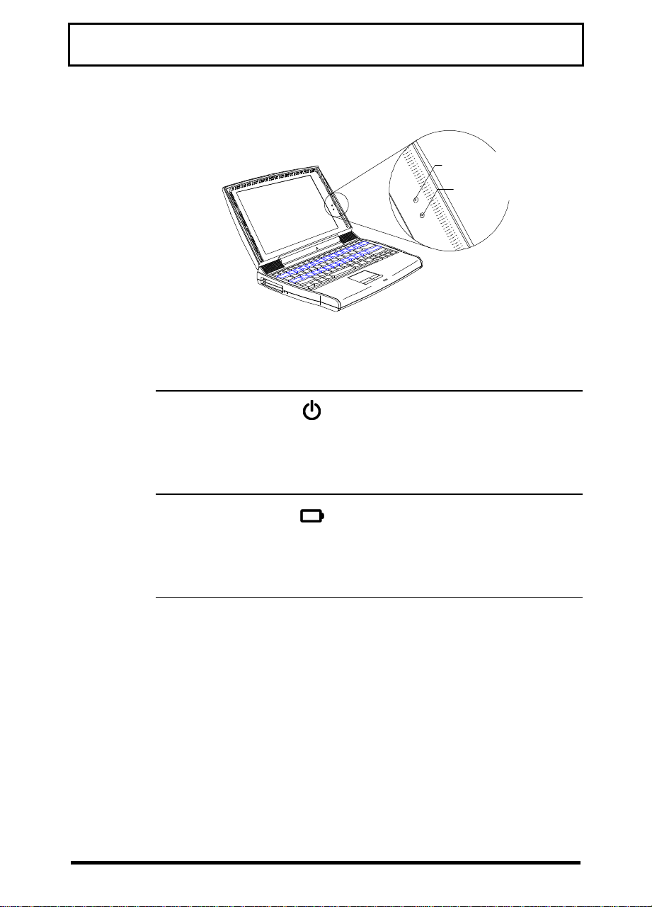
System Tour
Indicator Light Icon Description
Power Indicator
Battery Indicator
Power
Indicator
Battery
Indicator
Lights when power is on.
Flashes when the computer
is in suspend-to-memory
mode.
Lights when the battery pack
is charging.
Flashes when battery power
is low.
16
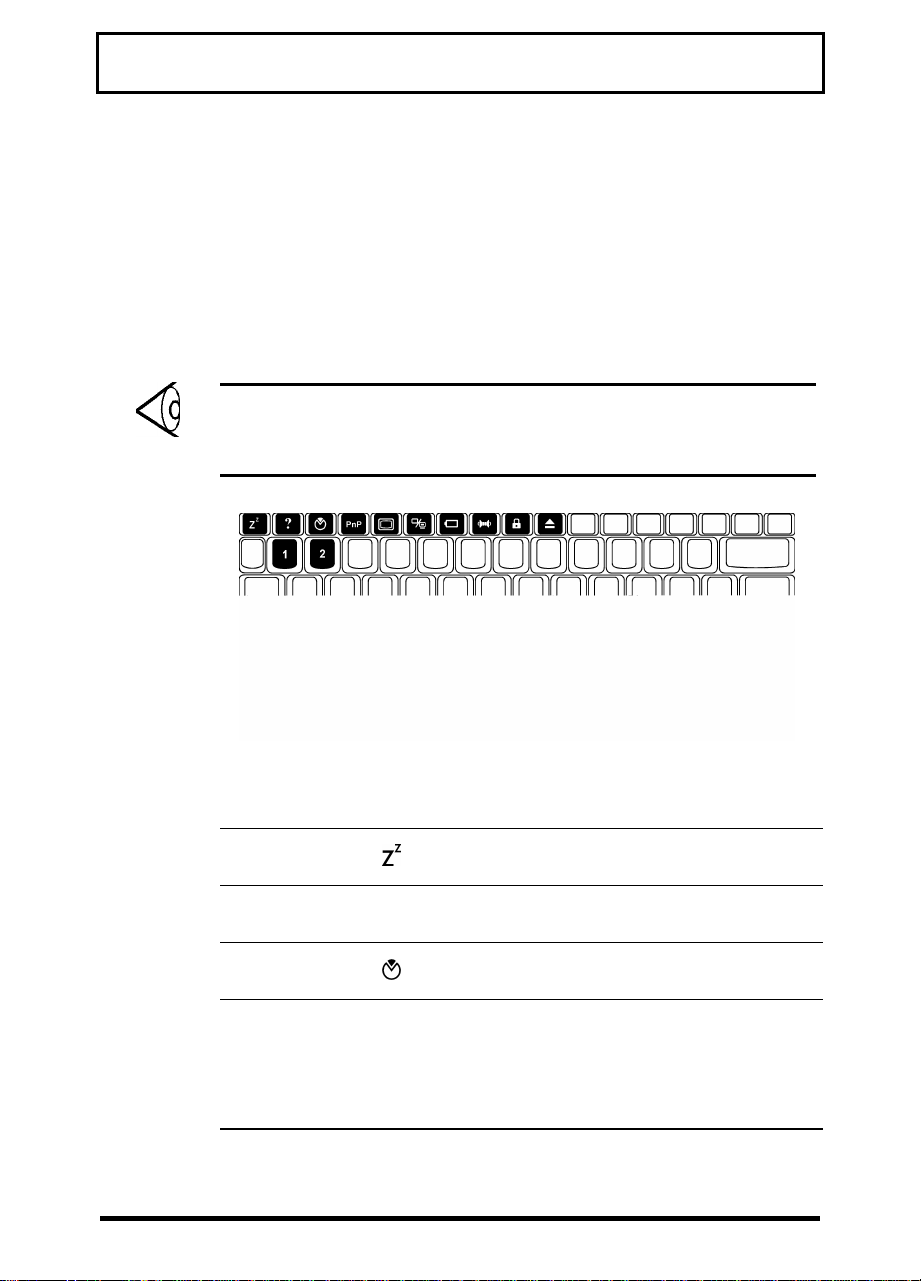
Page 25

System Tour
Keyboard
The computer’s full-size keyboard includes lock
keys, an embedded keypad with cursor-control
keys, Windows 95 keys, twelve function keys that
act as “hot keys” when used in combination with
the special Fn key.
The keyboard also includes a built-in touchpad
pointing device, an automatic tilt feature, and a
comfortable palm rest to provide optimum
ergonomics.
Lock Keys
The computer keyboard contains three lock keys
that act as toggles: Caps Lock, NumLk, and ScrLk.
NumLk and ScrLk require using the Fn key as part
of a key combination. The first time you press one
of these keys or key combinations, you turn on its
function; the next time, you turn off its function,
and so on.
17
Page 26

System Tour
Tip: When entering a lot of numeric data, toggle
on NumLk or attach an external keypad as
described on page 70.
Key Description
Caps Lock When Caps Lock is on, alphabetical
characters appear in uppercase as you
type them.
18
Fn+NumLk
(Fn+F11)
Fn+ScrLk
(Fn+F12)
When Num Lock After Boot is enabled
in the BIOS setup utility (see page 101)
and Num Lock is on, the embedded
keypad is in numeric mode. The keys
function as a numeric keypad, complete
with arithmetic operators +, -, *, and
/—just like the keypad on a standard
keyboard.
When Scroll Lock is on, the screen
moves up or down one line when you
press the ↑ or ↓ key. (Scroll Lock may
not work in some applications.)
Page 27

System Tour
Embedded Keypad
The embedded keypad functions like a desktop
numeric keypad. It is marked by small characters
printed in the upper right corner of the keycaps.
(For simplicity, cursor-control symbols are not
printed on the keycaps.)
To Use With NumLk On With NumLk Off
Numeric keys Use the keypad
keys in the usual
way
Cursor-control
keys
Main
keyboard keys
(letters, etc.)
Press and hold
Shift while using
the keypad keys
Press and hold
Fn while using
the keypad keys
Press and hold
Fn and Shift
while using the
keypad keys
Press and hold
Fn while using
the keypad keys
Use the keypad
keys in the
usual way
19
Page 28

System Tour
Windows 95 Keys
The computer keyboard contains two keys that
perform Windows 95-specific functions: ÿ and .
Key Description
ÿ key The same as clicking the Windows 95 Start
button. Pressing other keys in combination
with the ÿ key performs special functions:
ÿ+Tab Activate the next taskbar button
Shift+ÿ+M Undo Minimize All
ÿ+R Display Run dialog box
key Opens an application’s context menu. (The
same as the touchpad’s right button.)
+E Explore My Computer
+F Find Document
+M Minimize All
20
Page 29
System Tour
Hot Keys
The computer’s special Fn key, used in
combination with other keys, provides “hot-key”
combinations that access system control
functions, such as screen contrast, brightness,
volume output, and the BIOS setup utility.
Note: When using hot-key combinations, press
and hold the Fn key before pressing the other key
in the combination.
Hot Key Icon Function Description
Fn+Esc Suspend-to-
memory
Fn+F1
Fn+F2 Setup Enters the BIOS
Fn+F3
PnP
Help Displays the hot-key
?
Plug and Play
Configuration
Enters suspend-tomemory mode
list
setup utility
Performs system
configuration for
Plug and Play
operating systems
like Windows 95
21
Page 30

System Tour
Hot Key Icon Function Description
Fn+F4 Screen
Fn+F5 Display
Fn+F6 Fuel Gauge
Fn+F7 Speaker
Fn+F8 Lock System
Fn+F9 Eject Accesses the eject
Fn+Ctrl+↑
Blanks the screen to
Blackout
Toggle
On/Off
On/Off
Resources
(Password
Lock)
Volume Up Increases speaker
save power; to wake
up the screen, press
any key
Switches display
from the built-in
display, to an
external monitor, to
both built-in and
external if one is
connected
Toggles battery
gauge display on and
off. The gauge shows
the battery charge
percentage.
Shows a plug icon if
a powered AC
adapter is connected
to the computer;
shows a speaker icon
if speaker output is
on (Fn+F7); shows a
T icon if turbo mode
is on (Fn+2)
Toggles speaker
output on and off
Locks the computer
and requires a
password to unlock
it
menu described on
page 27
volume
22
Page 31

System Tour
Hot Key Icon Function Description
Fn+Ctrl+↓
Fn+Ctrl+→
Fn+Ctrl+←
Fn+ÿ+↑
Fn+ÿ+↓
Fn+ÿ+→
Fn+ÿ+←
Fn+↑
Fn+↓
Fn+→
Fn+←
Fn+1 CD Eject Ejects the CD-ROM
Fn+2 Turbo Mode
Volume Down Decreases speaker
volume
Balance Right Shifts speaker
balance to the right
Balance Left Shifts speaker
balance to the left
Brightness
Up
Brightness
Down
Contrast Up Increases screen
Contrast
Down
Fuel Gauge
Up
Fuel Gauge
Down
Fuel Gauge
Right
Fuel Gauge
Left
On/Off
Increases screen
brightness
Decreases screen
brightness
contrast
(not available for TFT
displays)
Decreases screen
contrast
(not available for TFT
displays)
With the fuel gauge
displayed, moves the
fuel gauge up
With the fuel gauge
displayed, moves the
fuel gauge down
With the fuel gauge
displayed, moves the
fuel gauge right
With the fuel gauge
displayed, moves the
fuel gauge left
drive
Toggles turbo mode
on and off
23
Page 32

System Tour
Eject Menu
The Fn+F9 hot-key combination brings up a
special eject menu that allows you to perform
several system configuration functions.
Eject Options:
Battery (Suspend-to-disk) ................ Change
CD-ROM Disc (Also Fn+1) ................... Eject
Mini Dock (Suspend) ....................... Change
Power Off ................................. Change
↑↓ = Move Highlight Bar, ↵ = Select, ESC = Exit
Select… To…
Battery
(Suspend to Disk)
CD-ROM Disc
(Also Fn+1)
Mini Dock
(Suspend)
Power Off Turn the computer off. If you are
Store all current data and system
information to the hard disk.
Open the CD-ROM drive (eject a
CD).
Undock the computer. Press the
dock lock and pull the dock
handle toward you to undock the
computer. (See the mini dock
manual for details.) Once the
computer is successfully
undocked, press any key to
resume.
using Windows 95, use the
Shutdown command to turn off
your computer.
24
Page 33

System Tour
Touchpad
The ergonomically-positioned touchpad is a
pointing device that senses movement on its
surface. The pointer moves on the screen in
response to the movement of your finger on the
surface of the touchpad.
q Move your finger across the touchpad to move
the pointer on the screen.
q Press the left and right buttons located at the
lower edge of the touchpad to “click.” These
buttons correspond to the left and right
buttons on a mouse.
q Alternatively, simply tap on the touchpad to
“click.”
25
Page 34

System Tour
Left
Function
Execution Double-
Selection Click
Drag Click and
Access
Context
Menu
Button
click
once
hold to
drag the
pointer
Right
Button
Click
once
Tapping on the
Touchpad
Tap twice quickly
Tap once
Tap twice quickly,
holding your finger
to the touchpad on
the second tap to
drag the pointer
To change Touchpad or pointer characteristics, see
page 95.
26
Page 35

System Tour
Notes:
Keep your fingers and the touchpad dry and clean
when using the touchpad.
The touchpad is sensitive to finger movements.
Hence, the lighter the touch, the better the
response. Tapping too hard will not increase the
touchpad’s responsiveness.
The touchpad works with most mouse drivers.
However, the touchpad driver supports special
functions that work uniquely with the touchpad.
We recommend you use the touchpad driver
instead of any other mouse driver.
Automatic Tilt
On models with a 12.1-inch display, the computer
can automatically tilt the keyboard to a six-degree
angle whenever you open the lid to provide a
comfortable typing angle similar to desktop
keyboards.
Tip: The automatic tilt feature and the palm rest
described on the next page help prevent repetitive
strain injury to your wrists and fingers.
27
Page 36

System Tour
To set the automatic tilt feature, follow these
steps:
1. Close the lid.
2. To enable the
automatic tilt feature,
slide the tilt switch,
located above the port
cover on the rear of
the computer, to the
right.
28
3. To disable the
automatic tilt feature,
slide the tilt switch to
the left.
Page 37

System Tour
Palm Rest
The curved palm rest located below the keyboard
provides a comfortable place to rest your hands as
you type.
29
Page 38

System Tour
Storage
The computer provides high-capacity storage on a
2.5-inch Enhanced-IDE hard disk. The computer
also contains a bay that accepts removable
modules—a CD-ROM drive, a floppy drive or a
second hard disk option.
Hard Disk
The hard disk can be upgraded when you need
more storage space. See page 82.
Module Bay
The computer’s module bay accommodates a CDROM drive module or a 3.5-inch floppy drive
module or an optional second hard disk. Other
modules may be available — consult your dealer
for details.
30
CD-ROM Drive Module
Hard Disk Module
Option
Floppy Drive Module
The CD-ROM drive module gives you portable
multimedia access. The floppy drive module can be
used as an internal or external unit. The optional
second hard disk gives you more storage space.
Page 39

System Tour
Ejecting a CD
To eject a CD, press Fn+1 or press the eject button
on the CD-ROM drive, or use your software
application’s CD eject command. (There may be a
few seconds delay before the CD is ejected.)
Tip: To eject a CD using Windows 95, doubleclick My Computer, right-click the CD-ROM drive
icon, and select the Eject command from the
context menu that appears.
Using the Floppy Drive Module Externally
You can use the floppy drive module externally
when a CD-ROM drive module is installed in the
module bay.
Warning! You cannot use the CD-ROM drive
module externally. Only the floppy drive
module can be used externally.
31
Page 40

System Tour
To use the floppy drive module externally, follow
these steps:
1. If the floppy drive module is installed in the
module bay, remove it by following the steps
described in the next section.
2. Open the port cover on the rear of the
computer, and connect the 25-pin connector
end of the floppy drive cable to the computer’s
parallel port.
3. Connect the other end of the cable to the floppy
drive module.
32
Page 41

System Tour
Swapping Modules
Follow these steps to swap modules:
1. Click the Windows 95
Start button and select
Shut Down to shut
down your computer.
2. When Windows finishes
shutting down, close
the display.
3. Turn the computer over
and locate the module
release lock on the
bottom of the
computer. With one
hand, slide and hold
the lock in the
direction of the arrow.
With the other hand,
press the module’s
half-moon-shaped
latch to release it and
pull out the module.
4. Insert the new module
securely into the
module bay until it
snaps into position.
5. Restart your computer.
33
Page 42

System Tour
Audio
The computer includes 16-bit stereo audio with a
built-in FM synthesizer, dual, angled speakers, a
built-in sensitive microphone, and two audio ports
on the computer’s left panel for external audio
devices. For information on connecting external
audio devices, see page 67.
The dual, angled speakers are located on both
sides of the display hinge and direct sound toward
you, creating a unique audio chamber that
produces excellent sound quality. The built-in
microphone uses both front- and side-pickup that
provides excellent quality audio recording.
34
Microphone
Left Speaker
Right Speaker
Page 43

System Tour
Audio Control
The computer provides several hot keys that allow
you to control audio output:
Hot Key Icon Function Description
Fn+F7 Speaker
On/Off
Fn+Ctrl+↑
Fn+Ctrl+↓
Fn+Ctrl+→
Fn+Ctrl+←
Volume
Up
Volume
Down
Balance
Right
Balance
Left
Toggles speaker
output on and off
Increases speaker
volume
Decreases speaker
volume
Shifts speaker
balance to the right
Shifts speaker
balance to the left
Caution: Audio settings you make with hot
keys are in effect only for a single session—
that is, until you turn off the computer. To
change settings for all sessions, use the audio
controls in Windows 95.
35
Page 44

System Tour
Ports
The computer’s ports allow you to connect
peripheral devices to your computer just as you
would to a desktop PC. The main ports are found
on the computer’s rear panel. The computer’s left
panel contains the computer’s multimedia ports
and PC card slots.
Rear Panel Ports
The computer’s rear panel contains the computer’s
main ports and connectors as shown in the
illustration below.
36
1
2
3
4
5
6
7
8
1 DC-in Port 5 Mini Dock Connector
2 PS/2 Port 6 External CRT Port
3 Serial Port 7 USB Port
4 Parallel Port 8 Infrared Port
Page 45

System Tour
Port Icon Connects to...
DC-in port AC adapter and power outlet
PS/2 port PS/2-compatible device
(PS/2 keyboard, keypad,
mouse)
Serial port
(UART16650compatible)
Parallel port
(EPP/ECPcompliant)
Mini dock
connector
External CRT
port
Serial device (serial mouse)
Parallel device (parallel
printer, external floppy drive)
Mini dock
37
Page 46

System Tour
Fast Infrared (FIR) Port
The computer’s FIR (fast infrared) port located on
the rear panel allows you to transfer data to IRaware machines without cables. For example, you
can transfer data between two IR-capable
computers, or send data to an IR-aware printer
without using a cable.
The infrared port is IrDA-compliant, and can
transfer data at speeds of up to 4 megabits per
second (Mbps) at a distance of up to one meter.
To use the infrared port, position two IR-aware
devices such that their IR ports are no more than
one meter apart and offset no more than 15
degrees.
38
When the two computers are in position, simply
begin the data transfer as you normally would. See
your file transfer software for details.
Page 47

System Tour
Left Panel Ports
The computer’s left side panel contains the
computer’s multimedia ports and PC card slots, as
shown in the illustration on the next page.
1 23
1 PC Card Slots
2 Microphone-in/Line-in Port
3 Speaker-out/Line-out Port
Port Icon Connects to...
PC Card slots Two type I/II PC Cards or
one type III Card
Microphone-in/
Line-in
Speaker-out/
Line-out
External microphone or line
input device
Amplified speakers or
headphones
PC Card Slots
The computer contains two PC card slots on the
left panel that accommodate two type I/II or one
type III PC card(s). Consult your dealer for
available PC card options. For information on how
to use the PC card slots, see page 65.
39
Page 48

System Tour
Multimedia Ports
The computer provides a Mic-In/Line-in port and a
Speaker-out/Line-out port on the left panel to
accommodate multimedia audio devices, such as a
microphone, speakers, or headphones. For
information on how to connect audio devices, see
page 67.
Notes:
Connecting external audio devices to the
computer’s multimedia ports automatically shuts
off the corresponding internal audio device. For
example, if you connect external speakers, the
internal speakers automatically shut off.
If you connect an audio device to the Mic-in or
Line in port, make sure to adjust the appropriate
input from the mixer. See the multimedia section
of your Windows 95 manual.
40
Page 49

System Tour
Security
The computer includes both hardware and
software features to secure your computer. A
hardware security notch located on the left panel
of the computer lets you connect a standard keybased computer security lock.
Circle or wrap a computer security lock cable
around an immovable object such as a table or
locked drawer handle. Then insert the lock into the
notch and turn the key to secure the lock.
System Resource Lock
A two-level password scheme protects your
computer from unauthorized access. When set,
just press Fn+F8 to lock all system resources. In
this situation, no one can access the computer
without entering the correct password. For more
information about setting and using passwords, see
page 111.
41
Page 50

3
Power
The computer operates on AC or battery power.
This section contains the information you need to
know to operate the computer on battery power.
This section also includes information about the
computer’s unique power management system.
Battery Pack
The computer uses a single high-capacity LithiumIon smart battery pack that gives you longer use
between charges. The battery pack includes the
following features:
q Lithium-Ion Technology. Lithium-ion
technology does not have the memory-effect
problem of nickel–cadmium (NiCd) batteries,
nor the temperature problem of nickel–metal–
hydride (NiMH) batteries. Lithium ion
batteries consistently provide the longest
battery life and the best solution for road
warriors.
q Battery Gauge. The battery pack contains a
built-in gauge that allows you to check the
battery charge level even when the battery is
not installed inside the computer.
q Battery-Low Warning. When the battery
charge level becomes low, the battery
indicator flashes at regular intervals, warning
you that the battery pack’s power is low and
needs to be recharged.
42
Page 51

Power
Tips:
Whenever possible, use the AC adapter. The
battery will come in handy when you travel or
during a power failure. It is advisable to have an
extra fully-charged battery pack available for
backup.
If the computer is to be stored for more than two
weeks, it is best to remove the battery pack.
Battery power from a fully charged battery pack
depletes in roughly a week with the computer in
suspend-to-memory mode.
Warning! Do not expose the battery pack to
temperatures below 32ºF (0ºC) or above 140ºF
(60ºC).
Removing and Installing the Battery Pack
To remove the battery pack, follow these steps:
1. Turn off the computer, or connect the AC
adapter to the computer.
2. Press the battery compartment cover latch and
slide it toward the front of the computer.
3. Pull out the battery pack.
43
Page 52

Power
To install the battery pack, simply reverse the
procedure as follows:
1. Insert the battery pack into the battery
2. Slide the battery compartment cover latch
compartment.
toward the rear of the computer until it snaps
into position.
44
Charging the Battery
To charge the battery, place the battery pack
inside the battery compartment and plug the AC
adapter into the computer and an electrical outlet.
Depending on the state of the battery and how the
computer is being used, the computer uses one of
three charging modes: Rapid Charge, Charge-InUse, and Trickle Charge.
Page 53

Power
Rapid Charge
The computer uses rapid charge when the
computer is in suspend mode with a powered AC
adapter connected. Using rapid charge, a depleted
battery charges fully in approximately two hours.
Charge-In-Use
The computer uses charge-in-use when the
computer is in use with a powered AC adapter
connected. Using charge-in-use, a depleted battery
charges fully in approximately four hours.
Trickle Charge
When the battery is fully charged and a powered
AC adapter is connected, the computer uses
trickle charge to maintain the battery charge and
prevent the battery from draining while the
computer is in use.
Tip: We suggest that you charge the battery pack
while you sleep. For example, charging the
battery the night before traveling provides a fully
charged battery for use the next day.
Checking the Battery Level
The computer provides three ways to check the
battery charge level:
q With the onscreen fuel gauge
q With the Windows 95 battery indicator
45
Page 54

Power
q With the battery-pack gauge
Onscreen Fuel Gauge
The onscreen fuel gauge provides a graphic
representation and shows the percentage of the
present battery level. To view the onscreen fuel
gauge, press Fn+F6. (If a powered AC adapter is
connected, a plug icon shows in the onscreen fuel
gauge.)
Press and hold Fn and the cursor keys to move the
fuel gauge around the screen. Press Fn+F6 again
to hide the fuel gauge.
Note: When the battery is charged to the
maximum, it shows a 99% charge. If you see a
??% charge, it means a battery is not installed.
46
Windows 95 Battery Indicator
Rest the pointer on the taskbar battery icon to
display the current power level. (If a powered AC
adapter is connected, a plug icon replaces the
battery icon on the taskbar.) Double-click the
taskbar icon to display the Power dialog box. You
can also access this dialog box via the Power icon
from Control Panel.
Page 55

Power
Battery Pack Gauge
The battery pack gauge allows you to check the
battery charge level when it is not installed in the
computer. Simply press the fuel gauge button on
the battery pack.
The lights on the fuel gauge show the charge level
as follows:
Lights (LEDs) Lit Charge Level
lllll
¡
llll
¡¡
lll
¡¡¡
ll
¡¡¡¡
l
¡¡¡¡ (blinking)
-
100%
≈80%
≈60%
≈40%
≈20%
<20%
Optimizing Battery Life
The battery pack can be recharged approximately
500 times. Follow these suggestions to optimize
battery life and maximize battery power:
q Purchase an extra battery pack.
47
Page 56

Power
q Set the When Lid is Closed parameter to
q Use the AC adapter whenever possible,
q Keep the battery pack in the computer when
q Set the Display Always On parameter to
q Eject any PC card from the card slot when not
q Store the battery pack in a cool, dry place.
Suspend to Disk. See page 108.
reserving the battery for on-the-go computing.
the computer is powered by the AC adapter. A
constant trickle charge maintains the battery
level. The charge-in-use function also charges
the battery pack.
Disabled to save power. See page 109.
in use because PC cards draw extra power.
when not in the computer. The higher the
storage temperature, the faster the battery
pack discharges. The recommended storage
temperature is 40º to 86ºF (10º to 30ºC).
48
Low-Battery Warning
You don’t have to be concerned about battery
power when you use the computer with the AC
adapter connected. However, when you operate the
computer on battery power, pay attention to the
battery indicator ( ). When less than 10 percent
charge is left in the battery, the following signals
warn you of the low-battery condition:
Page 57

q The battery indicator (
Power
49
Page 58

Power
The following table gives you the recommended
courses of action when you encounter a lowbattery warning.
soon as possible to prevent data loss.
Situation Recommended Action
AC adapter and
power outlet are
available
An extra fullycharged battery
pack is available
1. Connect the AC adapter to the
computer to begin charging the
battery.
2. Resume work.
If you want the battery to recharge
faster, close the display or press
Fn+Esc ( ) to enter suspend
mode.
1. Press Fn+F9.
2. Select Battery and press Enter
to enter suspend to disk mode.
3. After the computer has
powered off, open the battery
compartment cover.
4. Remove the used up battery
pack.
5. Install the new battery pack.
6. Press any key or open the
display to resume work.
Remember to recharge the old
battery pack.
50
AC adapter,
power outlet or
extra battery
pack is not
available
Close the display to enter suspend
mode.
Page 59

Power
Advanced Power
Management
The computer supports the Advanced Power
Management (APM) standard defined by Microsoft
and Intel.
Tip: Advanced Power Management greatly
prolongs battery life. Use APM whenever possible.
To use Advanced Power Management, follow these
steps:
1. Click the Start button and select Settings,
Control Panel.
2. Double-click the Power icon in Control Panel.
3. Set the power management mode to Advanced.
If you do not see the Power icon in Control Panel,
refer to your Windows user’s manual for details.
51
Page 60

Power
Heuristic Power Management
The computer uses a new power management
technique called Heuristic Power Management
(HPM) to take advantage of APM’s power-saving
features without degrading performance. HPM
allows the computer to provide maximum power
conservation and maximum performance.
Power-management methods used by most
computers are timer-based. You set time-out
values for the display, the hard disk, and other
devices. The system then puts itself to sleep when
it detects inactivity that exceeds the times you set.
The problem with this is that no two users are
alike. Each of us has his or her own habits when
using the computer, which makes timer-based
power management ineffective.
52
HPM is a “self-learning” method. With HPM, the
system manages its power according to the way
you use the machine. In effect, the computer
delivers maximum power when you need it, and
saves power when you don’t need the maximum—
all without any intervention from you. There are no
timers to set, nothing to enable or disable. The
HPM system figures out everything for you.
Page 61

Power
Using HPM, the computer automatically suspends
its operations—that is, enters suspend mode—in
response to a hot key or in response to various
events and conditions. Depending on the When Lid
Is Closed setting in the BIOS setup utility (see
page 108), the system enters one of two suspend
modes:
q Suspend to Disk
q Suspend to Memory
Note: If an external monitor is connected to the
computer, the computer does not enter either
suspend mode when you close the display. To
enter suspend mode, disconnect the external
monitor, and then open and reclose the display.
Suspend to Disk
Upon entering suspend-to-disk mode, the
computer stores all current data and system
information on the hard disk in a file created by
the Sleep Manager utility (see page 85). Upon
return to normal mode, the computer restores the
data from the hard disk and resumes where you
left off.
If the When Lid Is Closed setting in the BIOS setup
utility is set to Suspend To Disk and the suspendto-disk file created by Sleep Manager is present
and valid, the computer automatically enters
suspend-to-disk mode when:
q You close the display
53
Page 62

Power
q Battery power becomes low while the
q The battery fails without a powered AC
The computer exits suspend-to-disk mode and
returns to normal mode when you open the
display. (Make sure a charged battery pack is
installed and/or a powered AC adapter is
connected before you open the display.)
computer is in suspend-to-memory mode
adapter connected
Caution: If the battery runs out of power
while the AC adapter is not connected, the
computer enters suspend-to-disk mode,
regardless of the When Lid Is Closed setting.
Suspend to Memory
Upon entering suspend-to-memory mode, the
computer stores all current data and system
information in memory. Upon return to normal
mode, the computer restores the data from
memory and resumes where you left off.
If the When Lid Is Closed setting in the BIOS setup
utility is set to Suspend To Memory, the computer
automatically enters suspend-to-memory mode
when:
q You close the display
q You press the suspend hot key Fn+Esc ( )
q There is sustained inactivity
54
Page 63

Power
q The battery fails without a powered AC
adapter connected
Note: The computer also enters suspend-tomemory mode whenever an attempt to suspend to
disk fails—for example, if the suspend-to-disk file
is absent or invalid.
When the computer enters suspend-to-memory
mode, the power indicator ( ) flashes.
The computer exits suspend-to-memory mode and
returns to normal mode when:
q You open the display
q You press any key
q Resume On Schedule is enabled in setup, and
the selected date and time occur
For information about Resume On Modem Ring and
Resume On Schedule, see page 110.
55
Page 64

Peripherals and Options
The computer provides excellent connectivity and
expansion capabilities. This section describes how
to connect peripherals and hardware options to
the computer and how to upgrade your computer.
(For a complete list of available options and
upgrades, consult your dealer.)
Printers
The computer supports both parallel and serial
printers. To connect a parallel printer, plug the
printer cable into the parallel port ( ) on the
computer’s rear panel.
4
To connect a serial printer, plug the printer cable
into the serial port ( ) on the computer’s rear
panel.
56
Page 65

Peripherals and Options
PC Cards
Credit-card-sized PC cards (PCMCIA cards)
enhance the usability and expandability of your
computer. The computer provides two type I/II PC
Card slots (or one type III slot) on the computer’s
left side panel. Common type II cards include flash
memory, SRAM, fax/data modems, LAN and SCSI
cards. The type III cards most often used are 1.8inch ATA drives and cellular modems.
The computer supports Zoomed Video port
functionality which allows your computer to
support hardware MPEG in the form of a ZV PC
card.
To install a PC card:
Insert a type I/II PC
card into the desired
slot, or insert a type III
card or ZV card into the
lower or bottom slot.
Refer to the card’s user manual for details on how
to install and use the card, including any cable
connections needed, such as a network cable.
To eject a PC card, first exit the application that is
using the card. Then:
57
Page 66

Peripherals and Options
Flip out the slot eject
button of the slot where
the card is inserted
and …
58
Page 67

Peripherals and Options
Audio Devices
You can connect audio devices to the line-in ( )
and line-out ( ) ports on the computer’s left
panel. Use the line-in port to connect a 3.5-mm
mini-jack microphone or other line-in device. Use
the line-out port to connect external amplified
speakers or headphones.
Note: When you connect a device to the line-in
port, make sure to turn off the appropriate input
from the mixer. For more information, see the
multimedia section of your Windows 95 user’s
guide.
59
Page 68

Peripherals and Options
External Monitor
You can connect an external monitor to the CRT
port ( ) on the computer’s rear panel. See your
monitor manual for any additional instructions.
60
Page 69

Peripherals and Options
External Keyboard
You can connect any PS/2-compatible keyboard to
the computer. Simply plug the external keyboard
into the PS/2 connector (
rear panel.
) on the computer’s
61
Page 70

Peripherals and Options
External Keypad
You can connect any PS/2-compatible numeric
keypad to the computer. Simply plug the keypad
into the PS/2 connector (
rear panel.
) on the computer’s
62
Page 71

Peripherals and Options
External Pointing Device
You can connect a serial or PS/2-compatible
mouse or similar pointing device to the computer.
To connect a serial pointing device, plug the device
into the serial port ( ) on the computer’s rear
panel.
Serial mouse
Note: To enable the serial mouse, use the Add
New Hardware tool in the Windows 95 Control
Panel.
To connect a PS/2-compatible pointing device,
plug the device into the PS/2 port (
computer’s rear panel.
PS/2 mouse
Note: Installing an external PS/2 pointing device
disables the built-in touchpad.
) on the
63
Page 72

Peripherals and Options
USB Devices
You can connect a USB (Universal Serial Bus)
peripheral device to your computer. This
peripheral standard allows you to connect USB
devices to your computer without using up your
system resources.
Most USB devices have a built-in USB port onto
themselves which allows you to daisy-chain other
USB devices.
64
Page 73

Peripherals and Options
Mini Dock
The mini dock allows you to connect your
computer to various peripherals, and includes two
additional CardBus slots. Consult your dealer for
details. For connection instructions, see the guide
included with the mini dock.
65
Page 74

Peripherals and Options
Floppy Drive Cable
The floppy drive cable allows you to use your
floppy drive module externally. To connect the
cable, open the computer’s rear port cover and
connect the 25-pin connector end of the floppy
drive cable to the computer’s parallel port ( ).
Then connect the other end to the floppy drive
module.
66
Page 75

Peripherals and Options
PS/2 Y-Bridge Cable
The PS/2 Y-bridge cable allows you to connect a
PS/2 mouse and a PS/2 keyboard to the
computer’s PS/2 port. Plug the single-connector
end of the Y-bridge cable into the computer’s PS/2
port. Then attach the connector with the mouse
icon to the PS/2 mouse cable, and the connector
with the keyboard icon to the PS/2 keyboard.
67
Page 76

Peripherals and Options
File Transfer Cable
You can use the file transfer cable to transfer data
between the computer and other computers.
Connect one end of the file transfer cable to the
parallel port ( ) on the computer’s rear panel, and
connect the other end to the other computer’s
parallel port. Then use your file transfer utility to
perform the transfer.
68
Tip: Use the computer’s serial infrared (SIR) port
to transfer data between the computer and
another serial-aware computer. See page 45.
Page 77

Peripherals and Options
Battery Pack
It is good practice to have a spare battery pack
around, especially when you travel. The Li-Ion
(lithium-ion) smart battery supplies more power
than a conventional NiMH (nickel metal-hydride)
battery. With power management, you get even
more power on-the-go.
AC Adapter
You can purchase an additional AC adapter for
your computer or mini docking station.
69
Page 78

Peripherals and Options
Memory Upgrades
Memory is upgradeable up to 128 MB, employing
64-bit soDIMMs (small outline Dual Inline Memory
Modules) in 8, 16, 32 and 64 MB configurations.
The following table lists the possible memory
configurations.
Slot 1 Slot 2 Total Memory
16 MB 16 MB 32 MB
0 MB 32 MB 32 MB
32 MB 0 MB 32 MB
8 MB 32 MB 40 MB
32 MB 8 MB 40 MB
16 MB 32 MB 48 MB
32 MB 16 MB 48 MB
32 MB 32 MB 64 MB
0 MB 64 MB 64 MB
64 MB 0 MB 64 MB
8 MB 64 MB 72 MB
64 MB 8 MB 72 MB
16 MB 64 MB 80 MB
64 MB 16 MB 80 MB
32 MB 64 MB 96 MB
64 MB 32 MB 96 MB
64 MB 64 MB 128 MB
70
Both memory slots are accessible via a memory
expansion door on the base of the computer.
Page 79

Peripherals and Options
Caution: When installing memory, we
recommend you seek the help of a qualified
service technician. Improper installation can
damage the memory module or the computer.
Warning! Electronic components can be
damaged by static electricity. To avoid
damage, always wear a wrist grounding strap
(available at most electronic stores) when
handling electronic components. Do not
remove the component from its anti-static
packaging until you are ready to install it.
Follow these steps to install additional memory:
1. Power down your
computer. If you are
using the AC adapter,
disconnect it from the
power outlet.
2. Close the display lid.
3. Turn the computer
over to access the
base.
71
Page 80

Peripherals and Options
4. Remove two screws
that secure the
memory door and lift
the door up.
5. Insert the memory
module diagonally
into the slot, and then
gently press down on
the module until it
clicks into place.
6. Replace the memory
door and secure it
with the screw.
7. Open the display to
turn on the computer.
After new memory modules have been installed,
the system automatically detects and reconfigures
the total memory size.
72
Page 81

Peripherals and Options
Hard Disk Upgrades
Larger capacity hard disks are available as an
upgrade. The computer uses a 2.5-inch EnhancedIDE hard disk. The following table shows the
currently supported hard disks. Consult your
dealer for additional hard disks that may be
available.
Vendor Model CapacityCylinders Heads Sectors
IBM DTCA
23240
IBM DTCA
24090
Follow these steps to install a replacement hard
disk:
3.0 GB 6304 16 63
4.0 GB 7944 16 63
1. Power down your
computer. If you are
using the AC adapter,
disconnect it from the
power outlet.
2. Close the display lid.
3. Turn the computer
over to access the
base.
73
Page 82

Peripherals and Options
4. Remove two screws
that secure the hard
disk door; then press
the hard disk door
release latch and lift
the door up.
5. Lift up (1) and slide
out (2) the hard disk.
74
Page 83

Peripherals and Options
Note: An additional hard disk can also come in
the form of a module that swaps with the floppy
drive or CD-ROM drive in the module bay. Refer
to your dealer for details.
75
Page 84

System Utilities
The computer comes pre-loaded with the following
system utilities and drivers:
q Sleep Manager suspend-to-disk utility
q Touchpad driver
q Display driver
q Audio driver
q System core logic driver
q File-transfer utility
q PC Card slot driver and application
Note: Your computer may also have several
application programs pre-loaded. To access the
application programs, click the Start button and
select the application folder. Then click the
program’s icon. For help with an application
program, consult the application’s user manual or
the program’s online help.
5
Sleep Manager
Sleep Manager is a utility that reserves a space on
the hard disk for the computer’s suspend-to-disk
feature. It creates a contiguous area on the hard
disk where the system saves your data and system
information when the suspend-to-disk feature is
activated.
76
Page 85

System Utilities
Note: Sleep Manager starts and adjusts the
space needed for suspend-to-disk mode
automatically every time you start Windows 95.
You do not need to access Sleep Manager for
routine use of your computer.
Accessing Sleep Manager
To access Sleep Manager, click the Windows 95
Start button. Then select Programs, 0V Suspend
Utility, Sleep Manager. The main Sleep Manager
window shown on the next page appears.
The Current Setting area shows the drive location
and size of the current hard disk space reserved
by Sleep Manager. The On Board Information area
shows the system memory resources that will be
stored when the system enters suspend mode. The
total of these resources is the recommended size of
the reserved hard disk space shown below the
current setting area.
77
Page 86

System Utilities
The Enable Indicator on Taskbar check box allows
you to choose whether or not a Sleep Manager
status icon appears on the Windows 95 taskbar.
Select this check box to enable the icon; clear the
check box if you prefer not to see the Sleep
Manager icon on the taskbar.
Note: The Sleep Manager taskbar icon appears
with an exclamation point if Sleep Manager’s
reserved space has not been created, or if APM is
not enabled. The icon appears with a red crossed
circle if the space has not been created and APM
is also not enabled. For more information about
APM, see page 59.
When the Sleep Manager icon is displayed on the
taskbar, you can display the current status of
Sleep Manager by simply resting the mouse
pointer on the icon. Or you can double-click the
icon to access Sleep Manager,
78
Creating Reserved Space
The Create button at the top of the Sleep Manager
window tells Sleep Manager to find and reserve a
contiguous area on the hard disk for use in
suspend-to-disk mode.
Note: When suspend-to-disk mode is started, the
system checks to see that space been reserved. If
it has not (or the amount of system memory has
been changed since a space was reserved), Sleep
Manager starts automatically and begins the
Page 87

System Utilities
Page 88

System Utilities
Sleep Manager checks the system configuration
and displays the recommended size. The drive
where the space will be created is defined by the
system and will be the first available logical drive
which has the requested contiguous free disk
space on it. The recommended size is the
minimum size needed to save the current system
status.
If Sleep Manager cannot find the required space on
the hard disk during the space creation process, it
displays the message “Not Enough Space for
Allocation.”
Not Enough Space for Allocation
When Sleep Manager creates the space on the
hard disk, several situations can cause the
appearance of the message Not Enough Space for
Allocation:
80
q The amount of free space on the drive is less
than Sleep Manager needs. If the total
amount of free space on the drive is less than
the recommended size shown on the Sleep
Manger window, delete some unnecessary
files from the hard disk to make room. Then
re-run Sleep Manager.
q The hard disk has enough free space, but the
free space exists as small fragments. The free
disk space that Sleep Manager requires must
be contiguous. To solve this problem, run the
Windows 95 Disk Defragmenter utility. Then
re-run Sleep Manager.
Page 89

System Utilities
q You are using disk compression and the
amount of free space on the uncompressed
host drive is less than Sleep Manager needs.
Sleep Manager works with most compression
software. However, Sleep Manager can only
create reserved space on the uncompressed
host drive. If the free space on the host drive
is small (as it usually is), use the appropriate
commands in your compression software to
enlarge the size of the host drive. Then re-run
Sleep Manager.
Removing a Reserved Space
If you want to use or take back Sleep Manager’s
reserved space, click Sleep Manager’s Remove
button.
Caution: Removing Sleep Manager’s reserved
space prevents the system from entering
suspend-to-disk mode, and is not
recommended.
When you click Sleep Manager’s Remove button,
the following dialog box appears:
Click Ok to confirm that you want to delete the
Sleep Manager file.
81
Page 90

System Utilities
Minimizing Sleep Manager
Click the Minimize button on Sleep Manager’s
window to minimize Sleep Manager and allow it to
run in the background. If the Enable Indicator on
Taskbar check box is selected, the Sleep Manager
icon will appear on the taskbar. You can then
restore the Sleep Manager window when you need
it, by double-clicking the taskbar icon. If the
Enable Indicator on Taskbar is not selected, you
must click the Windows 95 Start menu and select
Programs, 0V Suspend Utility, Sleep Manager to
restore Sleep Manager.
Exiting Sleep Manager
Select the Exit button to shut down Sleep
Manager.
82
Caution: Using the Exit button to shut down
Sleep Manager disables the automatic
adjustment of reserved disk space for suspendto-disk operations, and is not recommended.
Sleep Manager Troubleshooting Tips
The following table lists some error messages you
might see when using Sleep Manager and what to
do about them.
Page 91

System Utilities
Error Message Solution
BIOS not compliant
with Sleep Manager.
This machine does not
have a power
management unit. You
cannot run Sleep
Manager without PMU.
The APM driver for
Windows is not
installed. Use Windows
Setup to install the APM
driver before you run
Sleep Manager.
Requested disk space is
not enough /The
created file is not
contiguous.
The [directory name]
directory cannot be
created. Enter another
directory or try another
drive.
Sleep Manager can run
only on computers with a
compatible BIOS.
Sleep Manager can only
work on computers with a
power management unit
(PMU) installed.
See page 59 for
instructions on how to
enable advanced power
management (APM) on
your computer.
See page 89 for
information on how to
solve disk space problems.
The directory name you
specified is not valid. (You
can create only one
subdirectory at a time.)
The software has not
been successfully
installed. You must run
Setup again.
Sleep Manager is not
completely installed. Reinstall Sleep Manager.
83
Page 92

System Utilities
Uninstalling Sleep Manager
Uninstalling Sleep Manager removes the Sleep
Manager utility from your hard disk.
Caution: Uninstalling Sleep Manager does not
remove the hard disk space reserved for
suspend-to-disk mode. Therefore, you can still
use the suspend-to-disk feature. However,
uninstalling Sleep Manager prevents the
automatic adjustment of reserved disk space,
and is not recommended. (For information on
how to remove the reserved hard disk space,
see page 90.)
To uninstall Sleep Manager, follow these steps:
1. Click the Windows 95 Start button, and select
Programs, Sleep Manager, Sleep Manager.
2. Click Exit on the Sleep Manager main window
to shut down Sleep Manger.
3. Click the Windows Start button, and select
Settings, Control Panel.
4. Double-click the Add/Remove Programs icon in
Control Panel.
5. On the Install/Uninstall tab, select Sleep
Manager for Windows 95 and click
Add/Remove.
6. Follow the screen instructions to complete the
uninstallation.
84
Page 93

System Utilities
Touchpad Driver
The computer’s built-in touchpad works with most
mouse drivers, but the pre-loaded touchpad driver
provides additional functions that work only with
the touchpad.
To configure these additional functions, follow
these steps:
1. Click the Start button and select Settings,
Control Panel.
2. Double-click the Mouse icon.
3. In the Mouse property sheet, select the
TouchPad tab.
To see descriptions of the configuration options,
move the pointer over the option and press the
right touchpad button (right-click). When the
What’s This button appears, press the left
touchpad button to bring up online help for that
option.
85
Page 94

System Utilities
BIOS Setup Utility
The computer BIOS setup utility allows you to
configure the computer and its hardware settings.
The computer comes correctly configured, and you
do not need to run the BIOS setup utility to use
the computer. However, you might need to use the
BIOS utility if you want to customize the way your
computer works, or if you receive an error message
after making hardware or software changes.
With the BIOS setup utility, you can:
q Check the system configuration
q Change the system date, time, or speed
q Change the system startup sequence
86
q Set the power-saving suspend mode
q Set or change resume options
q Set, change, or remove a system password
Page 95

System Utilities
Press Fn+F2 to access the BIOS setup utility. You
will see the BIOS Utility main screen shown below.
BIOS Utility
About My Computer
System Configuration
Power Saving Options
System Security
Reset to Default Settings
↑↑↓↓ = Move Highlight Bar, ↵↵ = Select, Esc = Exit
Press ↑ or ↓ to highlight the menu item you want.
Then press Enter to access the highlighted item.
Press Esc to exit.
About My Computer
Selecting About My Computer presents you with
two screens of details about the computer and its
peripherals. These screens are for information
only; you cannot change the settings on these
screens.
87
Page 96

System Utilities
The following table tells you what each of the items
on the About My Computer screens are.
Item Description
System
Architecture
System BIOS BIOS version
System ID ID information on major components
Processor Processor type and speed
Coprocessor Coprocessor type
Internal Cache
(L1)
External Cache
(L2)
Total Memory Total memory size
Bank A Bank A memory module size and
Bank B Bank B memory module size and
System Peripherals
Graphics
Controller
System architecture information
Internal cache size and whether it is
enabled or not
External cache size and whether it is
enabled or not
type
type
Graphics controller type and video
memory size
88
Display Output Display type
Hard Drive 0 IDE 0 drive type and size (hard disk)
Hard Drive 1 IDE 1 drive type (CD-ROM or other
IDE drives)
Floppy Drive A Floppy drive A type
Floppy Drive B Floppy drive B type
Page 97

System Utilities
Item Description
Expansion Peripherals
PCMCIA Slot 0 Card presence in slot 0 (detected by
the socket service)
PCMCIA Slot 1 Card presence in slot 1 (detected by
the socket service)
Parallel Port Parallel port base address and IRQ
Serial Port Serial port base address and IRQ
IrDA (FIR) Infrared port base address and IRQ
Onboard USB USB port if enabled or not
AC Adapter Connected AC adapter information
Main Battery Installed battery type information
Onboard Audio
Base Address Audio base address
MPU Base
Address
IRQ Setting Audio IRQ settings
DMA Channel Audio DMA channels
Audio MPU-401 base address
89
Page 98

System Utilities
System Configuration
Selecting System Configuration presents a Basic
System Configuration screen, where you can
change several items in your computer’s
configuration.
Press ↑ or ↓ to move from one item to another, and
← or → to change settings. Press F1 to get help on
a selected item. Press Esc to exit the Basic System
Configuration screen and return to the main BIOS
Utility screen.
Date and Time
The current date is in “Day-of-the-week Month
Day, Year” format—for example, [Mon Aug 11,
1997]. The current time is in
“Hour:Minutes:Seconds” format. The system uses
a 24-hour clock—for example, 6:25:50 PM appears
as 18:25:50.
90
Floppy Drives
The default setting for Floppy Drive A is 1.44 MB
3.5-inch. Floppy Drive B is set to None, and it is
only enabled if you connect an additional external
floppy drive.
Page 99

System Utilities
Hard Disks
The Hard Disk 0 entry refers to the computer’s
internal hard disk. With this entry set to Auto, the
BIOS automatically detects the hard disk and
displays its capacity, cylinders, heads, and
sectors. Other hard disk settings are configured
automatically for optimum drive performance.
You can change the Hard Disk 0 entry to User if
you want to enter drive settings manually. To
determine your drive settings, check the data
found on your hard disk or supplied in the hard
disk vendor documentation.
Caution: We suggest that you leave this
parameter set to Auto to allow the BIOS to
auto-detect the drive settings at each boot-up.
The Hard Disk 1 entry is used when a CD-ROM
drive module or second IDE drive option is
installed in the module bay.
Num Lock After Boot
When set to Enabled, Num Lock After Boot tells
the computer to turn on Num Lock automatically
on startup, activating the keyboard’s embedded
numeric keypad. The default setting is Disabled.
91
Page 100

System Utilities
LCD Expansion Mode
When set to Enabled, LCD Expansion Mode allows
full-screen views in DOS mode. The default setting
is Disabled.
Internal Speaker
This parameter lets you enable or disable the
internal speaker. The default setting is Enabled.
Tip: You can also toggle the speaker on and off
by pressing the speaker hot key combination
Fn+F7.
Silent Boot
92
When set to Enabled, the computer shows the
computer logo onscreen and hides the POST
routine messages. The default setting is Enabled.
Fast Boot
When set to Enabled, the computer bypasses the
memory tests to speed up the boot-up process.
The default setting is Disabled.
 Loading...