

Page 1

& K DSWHU
System Board
System Board 1-1
This high-perform ance, 32-bit personal computer system is based on
the 486 series microprocessor. It features the single-chip upgrade
technology which allows maximum ease and flexibility for upgrading
the system. It is fully compatible with the IBM PC/AT and is suitable
for use as a W indows workstation, CAD/CAE/CAM workstation, UNIX
personal workstation or desktop PC.
The system board accommodates an ISA riser card slot and two 72pin SIMM sockets that can hold a m aximum mem ory of 36 MB. T he
system architecture is based on the VESA local bus featuring an
onboard VGA. The VGA memory is expandable to 1 MB or 2 MB.
In a LAN environment, the system supports 16-bit Arcnet cards,
Ethernet cards and Token Ring cards. It is f ully com patible with Novell
NetWare and Microsoft LAN Manager and also with SCO UNIX,
XENIX and OS/2 operating systems.
The system has a number of software-controlled security features.
These include power-on password, disk drive read/write control,
diskette boot control, serial- and parallel-port control, and a system
setup control.
Installing options such as memory modules, expans ion boards and an
upgrade CPU enhance system performanc e. This chapter gives stepby-step instructions on how to install these options.
Page 2

1-2 User’s Guide
1.1 System Board Layout
The system board has the following major components:
•
486SX, SX2, DX2, or DX4 series CPU
•
4-MB onboard RAM expandable to 36 MB
•
Two 72-pin SIMM sockets for memory upgrade
•
128-KB ROM for system BIOS and VGA BIOS
•
120-pin connector for ISA riser card
•
System clock/calendar
•
Two 9-pin serial ports
•
One 25-pin Centronics parallel port
•
PS/2-compatible keyboard and mouse interface
•
512-KB or 1-MB DRAM for onboard local bus VGA interface;
expandable to 1 MB (for GD-5424) or 2 MB (for GD5429)
•
Embedded fixed disk interface
•
Upgradable cache memory (128-KB or 256-KB)
•
Optional enhanced IDE interface
•
Optional power daughter board that enables the system to
support the 3.3V microprocessors
Figure 1-1 shows the board layout and the locations of the important
components.
Page 3
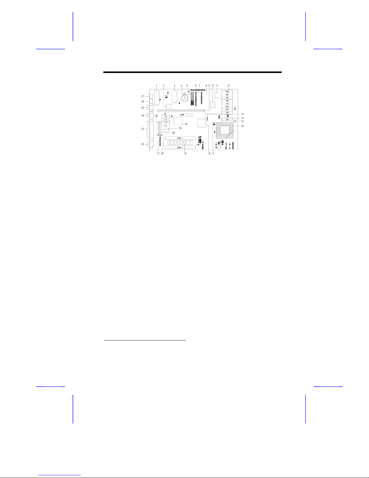
System Board 1-3
1. Keyboard controller 17. Power daughter board
2. M5105 super I/O controller 18. M1429G system chip
3. System and VGA BIOS 19. Onboard memory (4 MB)
4. RTC Battery 20. SIMM sockets
5. Power connector 21. VGA feature connector
6. IDE fixed disk connector #2* 22. VGA connector
7. IDE fixed disk connector #1 23. Parallel port
8. Diskette drive connector 24. COM2 port
9. ISA riser card connector 25. COM1 port
10. Local bus IDE controller* 26. PS/2 mouse connector
11. M1431 system chip 27. PS/2 keyboard connector
12. Second-level cache* 28. VGA upgrade sockets (1 MB)
13. Power daughter board connectors 29. VGA upgrade sockets (2 MB)
14. TAG RAM 30. Onboard VGA memory (512 KB)
15. Fan power connector 31. VGA chip
16. 486 CPU socket
Figure 1-1 System Board Layout
*
Optional
Page 4

1-4 User’s Guide
1.2 ESD Precautions
Electrostatic discharge (ESD) can damage your processor, disk drives,
expansion boards, and other components. Always observe the
following precautions before you install a system component.
1. Do not remove a component from its protective packaging until
you are ready to install it.
2. Wear a wrist grounding strap and attach it to a metal part of the
system unit before handling components . If a wrist strap is not
available, maintain contact with the system unit throughout any
procedure requiring ESD protection.
Integrated circuits are extremely susceptible
to electrostatic discharge. Do not handle ICs
unless you are a qualified service technic ian,
using tools and techniques that conform to
accepted industry practices.
1.3 Pre-installation Instructions
Follow these steps before you install a system component:
1. Turn off the system power and all the peripheral devices
connected to the unit before you open it.
2. Open the system according to the instructions in the housing
installation manual.
3. Follow the ESD precautions in section 1.2 before handling a
system component.
4. Remove any expansion boards or peripherals that block access
to the SIMM sockets or CPU socket.
5. See the following sections for specific instructions on the
component that you wish to install.
Page 5
System Board 1-5
Do not attempt the procedures described in
the following sections unless you are a
qualified service technician.
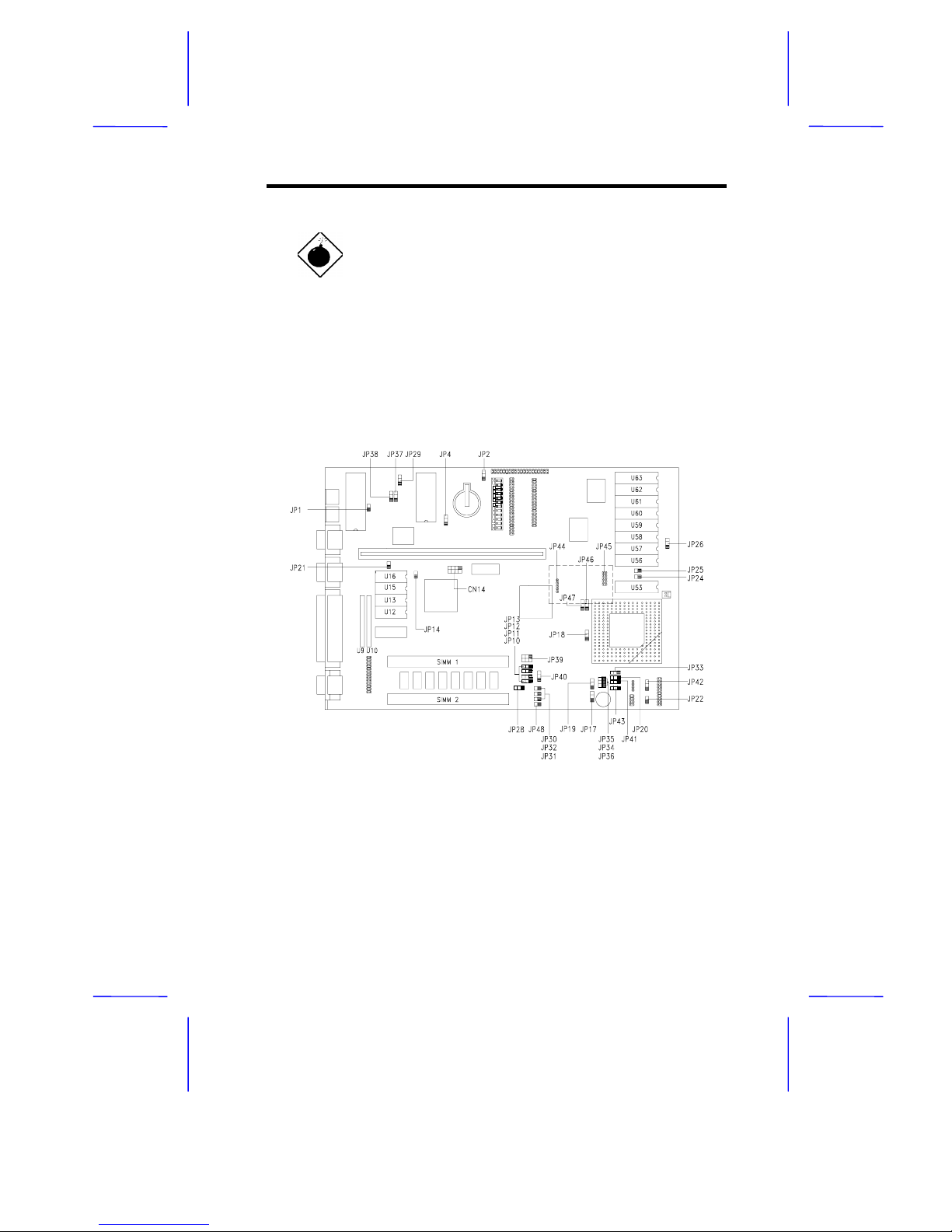
1.4 Jumper Settings
Figure 1-2 shows the jumper locations.
Figure 1-2 Jumper Locations
Page 6
1-6 User’s Guide
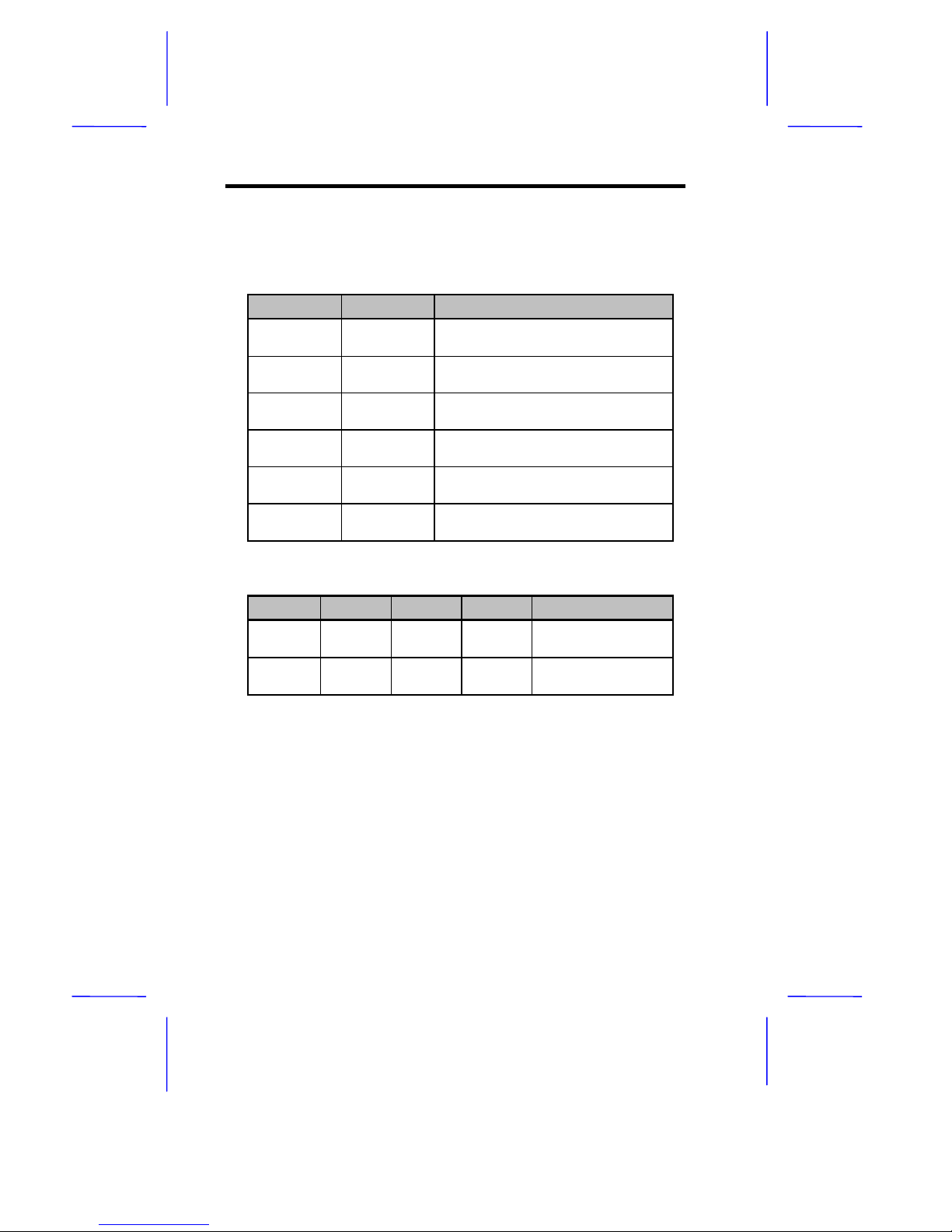
The following tables list the jumper settings and their correponding
functions.
Table 1-1 System Board Jumpers
Jumper Setting Function
JP2 1-2
2-3
Enable password check
Bypass password
JP14 Closed
Open
Enable onboard VGA
Disable onboard VGA
JP16 Open
Closed
Enable onboard local bus IDE
Disable onboard local bus IDE
JP21 Closed
Open
Enable onboard super I/O chip
Disable onboard syper I/O chip
JP28 1-2
2-3
Enable onboard memory
Disable onboard memory
JP37-38 1-2
2-3
Enable Reset button
Enable Suspend/Resume button
Table 1-2 CPU Clock Selection
JP10 JP17 JP19 CN14 CPU Clock
2-3 2-3 2-3 3-7 33 MHz (for SX/33,
DX2/66 or DX4/100)
2-3 2-3 2-3 4-8 25 MHz (for SX2/50
or DX2/50)
Page 7
System Board 1-7
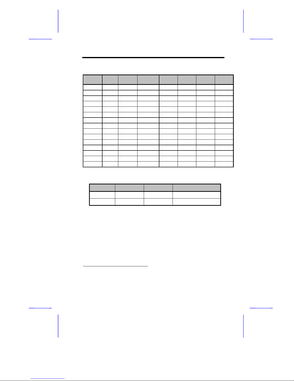
Table 1-3 CPU Type Selection
4861486 WB
2
Pentium
OverDrive
AMD
486/DX2
AMD
486/DX4
Cyrix
IBM
TI
JP11 1-2 1-2 1-2 1-2 1-2 2-3 2-3
JP12 1-2 2-3 2-3 1-2 1-2 1-2 2-3
JP13 1-2 1-2 1-2 1-2 1-2 1-2 2-3
JP18 2-3 1-2 1-2 2-3 2-3 2-3 2-3
JP20 2-3 2-3 2-3 2-3 2-3 1-2 2-3
JP30-32 Open Open Open Open Open Closed Open
JP33 1-2 1-2 1-2 1-2 1-2 2-3 1-2
JP34-36 Closed Closed Closed Open Open Open Open
JP39 1-2, 4-5 1-2, 4-5 1-2, 4-5 1-2, 4-5 1-2, 4-5 1-2, 4-5 2-3, 5-6
JP40-41 2-3 2-3 2-3 1-2 1-2 2-3 2-3
JP42 2-3 2-3 2-3 2-3 2-3 2-3 1-2
JP43 Open Open Open Open Open Open Open
JP46 1-2 2-3 2-3 1-2 1-2 1-2 1-2
JP47 1-2 1-2 1-2 1-2 1-2 2-3 1-2
JP48 Open Open Open Closed Open Open Open
Table 1-4 Cache RAM Size Selection
JP24 JP25 JP26 Cache Size
Open Closed 1-2 128 KB
Closed Closed 2-3 256 KB
1
Intel 486SX, SX2, DX, DX2 and DX4
2
Intel 486DX2 and DX4 with write-back internal cache
Page 8
1-8 User’s Guide
1.5 Installing Memory
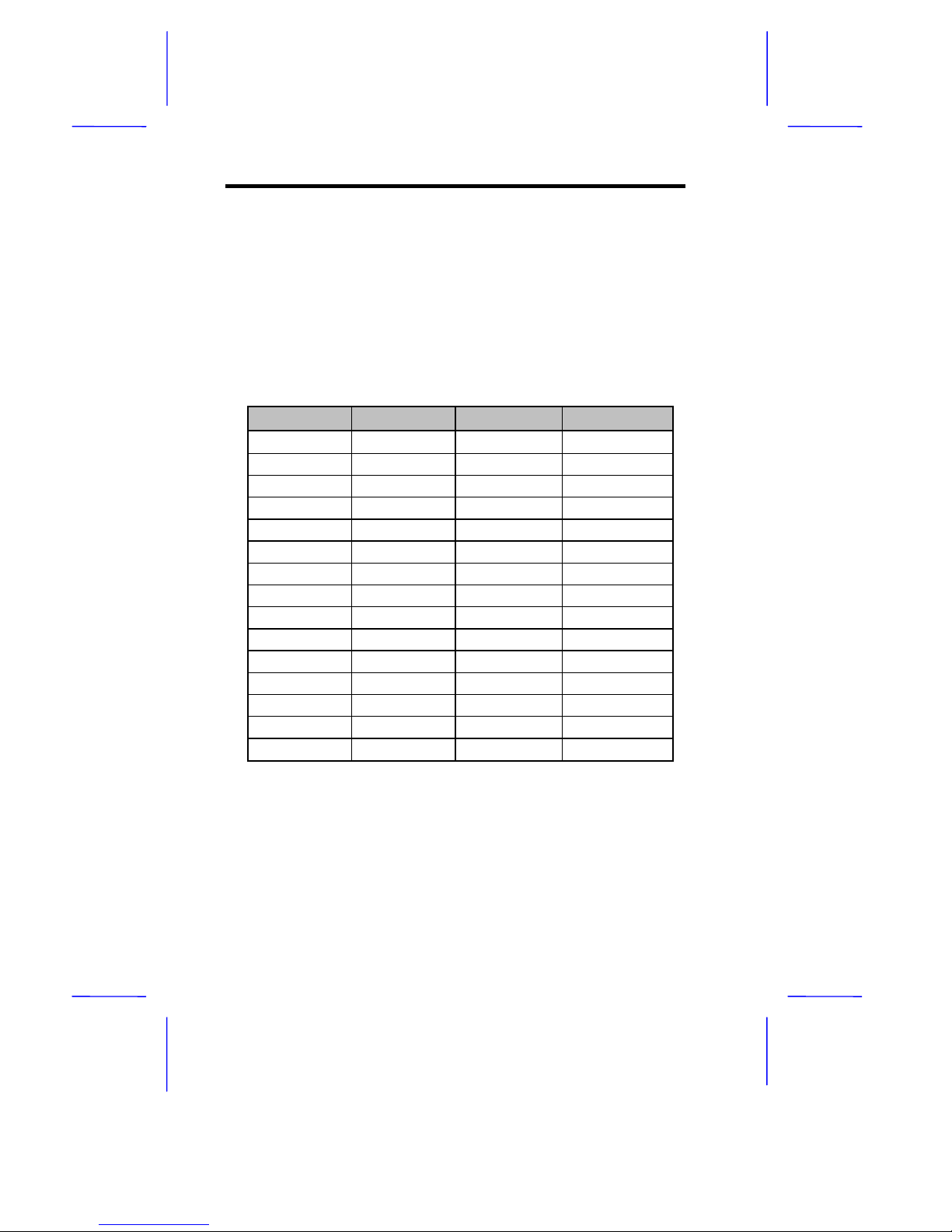
The system board has two 72-pin SIMM sock ets that accept 1-MB, 2MB, 4-MB, 8-MB, or 16-MB memory modules with 80 ns (or less)
DRAM speed. The maximum system memory size is 36 MB.
When installing additional memory, choose one of the SIMM
configurations listed in Table 1-5.
Table 1-5 Memory Configurations
Onboard Socket 1 Socket 2 Total
4 MB 4 MB
4 MB 1 MB 5 MB
4 MB 1 MB 1 MB 6 MB
4 MB 1 MB 2 MB 7 MB
4 MB 4 MB 8 MB
4 MB 4 MB 1 MB 9 MB
4 MB 4 MB 2 MB 10 MB
4 MB 4 MB 4 MB 12 MB
4 MB 4 MB 8 MB 16 MB
4 MB 16 MB 20 MB
4 MB 16 MB 1 MB 21 MB
4 MB 16 MB 2 MB 22 MB
4 MB 16 MB 4 MB 24 MB
4 MB 16 MB 8 MB 28 MB
4 MB 16 MB 16 MB 36 MB
Page 9
System Board 1-9
1.5.1 Installing a SIMM
Observe ESD precautions when installing
SIMMs. See section 1.2.
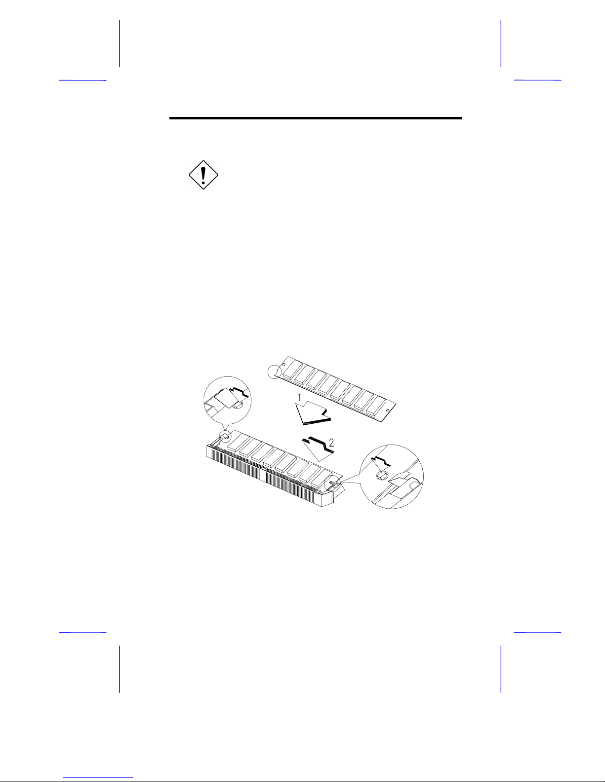
Follow these steps to install a SIMM:
1. Insert the SIMM into the socket at a slight angle, making sur e that
the cut edge of the SIMM touches the base of the circ le mark on
the SIMM socket.
2. Gently press the SIMM back against the holding clips on both
ends of the socket until the peg slips into the holes on the SIMM,
and the holding clips lock the SIMM into position. See Figure 1-3.
3. Check that the SIMM is securely seated in its slot and that both
ends are locked to the socket.
Figure 1-3 Installing a SIMM
Page 10
1-10 User’s Guide
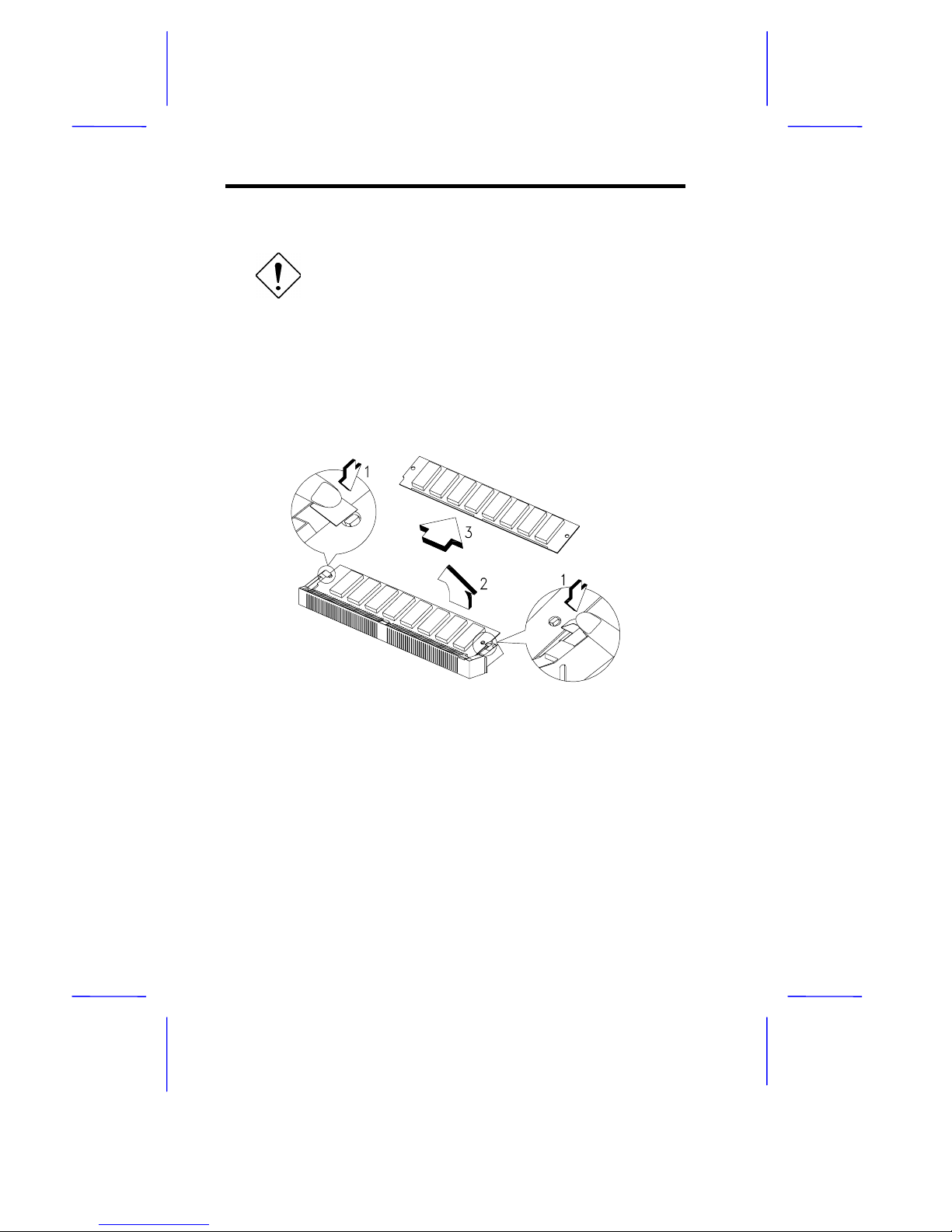
1.5.2 Removing a SIMM
Observe ESD precautions when removing
SIMMs. See section 1.2.
1. Press the holding clips on both sides of the SIMM outward to
release it.
2. Push the SIMM upward.
3. Gently pull the SIMM out of the socket.
Figure 1-4 Removing a SIMM
1.5.3 Reconfiguring the System
The system automatically detects the amount of memory installed.
Run Setup to view the new value for total system memory and mak e a
note of it.
Page 11

System Board 1-11
1.6 Upgrading the CPU
Conventional technology places the CPU on the same board as the
ISA bus logic, system memory and I/O interface. The entire system
board must be replaced to upgrade the CPU. Single-chip upgrade
technology gives you the flexibility to upgrade the CPU by simply
inserting a new CPU without replacing the entire system board.
1.6.1 Unpacking the Upgrade CPU
Unpack all items and inspect the contents. If any of the following
items are damaged or missing, contact your dealer immediately.
•
Upgrade CPU with heat sink
•
Electrostatic discharge (ESD) gloves
1.6.2 Installing an Upgrade CPU
Observe ESD precautions when installing
components. See section 1.2.
Before installing an upgrade CPU, check the following:
•
The heat sink is not oily
•
The heat sink is well attached to the CPU
The heat sink protects the CPU against excessive heat.
Follow these steps to install an upgrade CPU:
1. Turn off the system power.
2. Open the system and locate the CPU socket on the system
board. Refer to Figure 1-1 for location of the CPU socket.
3. Remove the CPU installed in the upgrade socket, if any.
Page 12
1-12 User’s Guide
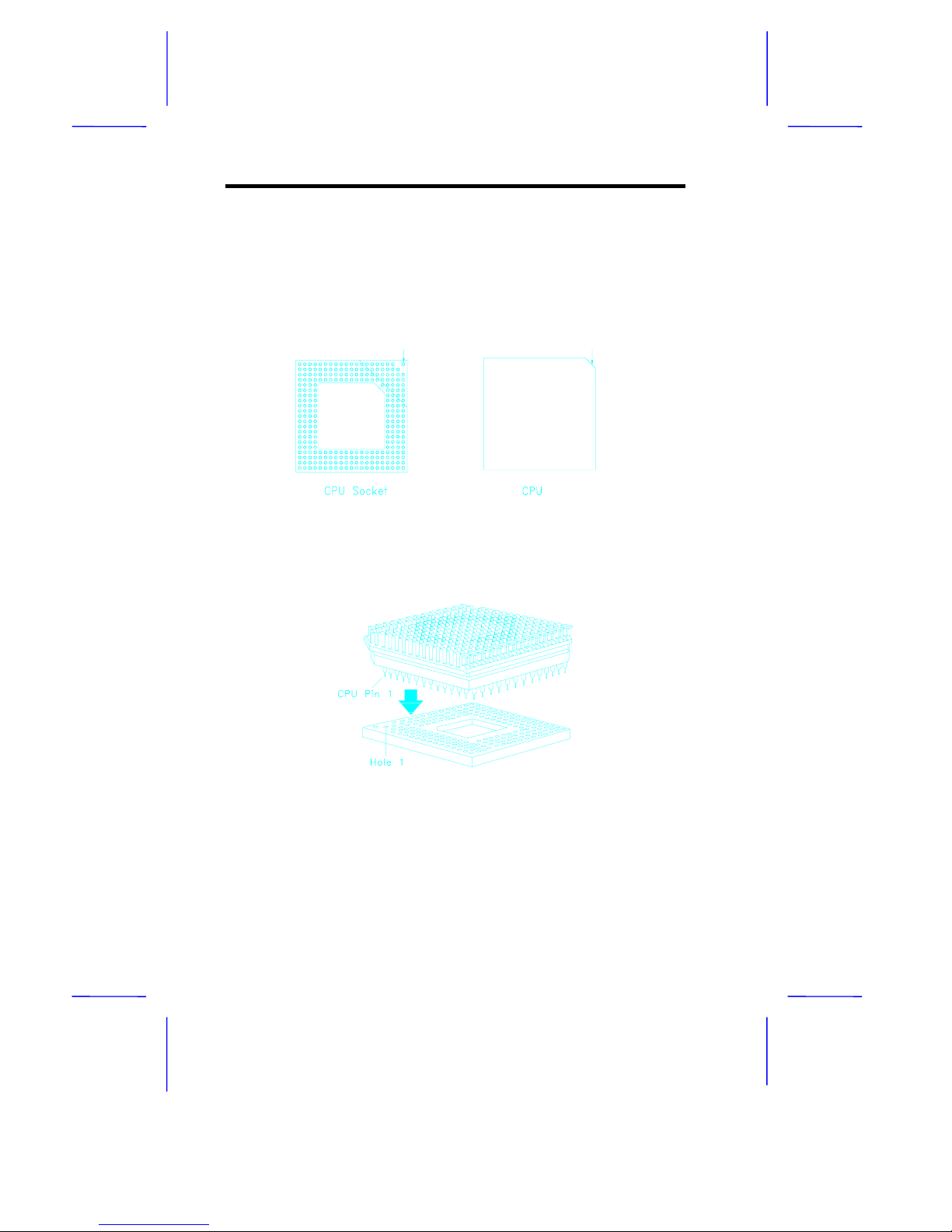
4. Insert the upgrade CPU (with the heatsink) into the upgrade
socket. Make sure that pin 1 of the CPU corresponds to hole 1 of
the upgrade socket (see Figure 1-6). The flat corner on the CPU
indicates pin 1. Insert the CPU pins into the socket pinholes
gently but firmly. Be careful not to bend any pins.
Figure 1-5 Pin 1 Indicator on the Upgrade CPUand Socket
Figure 1-6 Installing an Upgrade CPU
5. Set the required jumpers on the system board. Refer to section
1.4 for the jumper settings.
Pin 1 Indicator
Pin 1 Indicator
(flat corner)
Page 13

System Board 1-13
1.7 Power Daughter Boar d
The power daughter board enables the system to support a 3.3V
microprocessor. W ithout this board, your system can only support a
5V CPU.
Follow these steps to install the power daughter board:
Before installing, you must check first the
voltage requirement of your upgrade CPU.
1. Locate the power daughter board connectors marked as JP44
and JP45 on the system board. See Figure 1-1.
2. If your system board comes with a 5V CPU, then you will find
JP45 closed. Remove the jumper cap of JP45 and insert the
board into the connectors.
Page 14

1-14 User’s Guide
1.8 Upgrading VGA Memory
Observe ESD precautions when installing
components. See section 1.2.
The VGA memory is upgradable to 1 or 2 MB depending on your
onboard VGA chip. The system board m ay come with either a GD5424 or a GD-5429 VGA chip. If your board has a GD-5424, then your
VGA memory is expandable to 1 MB only. If your system board has a
GD-5429 VGA chip, then you can further expand your VGA memory to
2 MB. The additional memory allows your VGA to display higher
resolutions and more colors when the appropriate VGA driver is used.
Follow these steps to upgrade the VGA RAM to 1 MB:
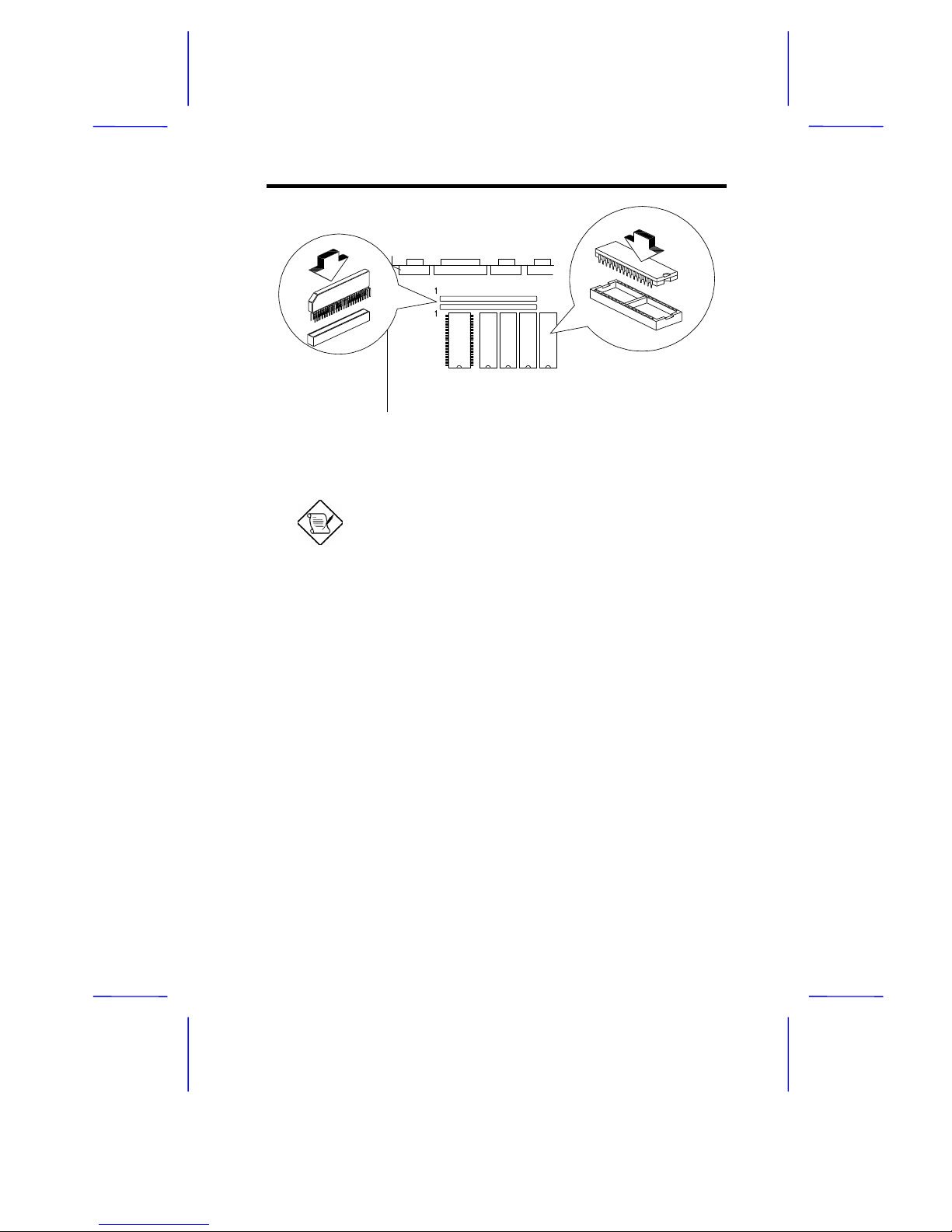
1. Locate the VGA memory expansion sockets on the system board
labeled U12, U13, U15 and U16. See Figure 1-7.
2. Gently but firmly insert a 44256 DRAM (256 Kb x 4, 70 ns DIP)
chip into each of the VGA memory expansion sockets.
To upgrade the VGA RAM to 2 MB:
1. Locate sockets U9 and U10 on the system board.
2. Insert a 512460 (256 Kb x 16, 70 ns ZIP) DRAM chip into eac h
socket. See Figure 1-7.
Page 15
System Board 1-15
U12 U13 U15 U16
U9
U10
514260 DRAM
44256 DRAM
Figure 1-7 Installing VGA RAM
You do not need to change any jumper settings
when upgrading the VGA memory.
Page 16
1-16 User’s Guide
1.9 Upgrading Cache Memory
To install cache chips, do the following:
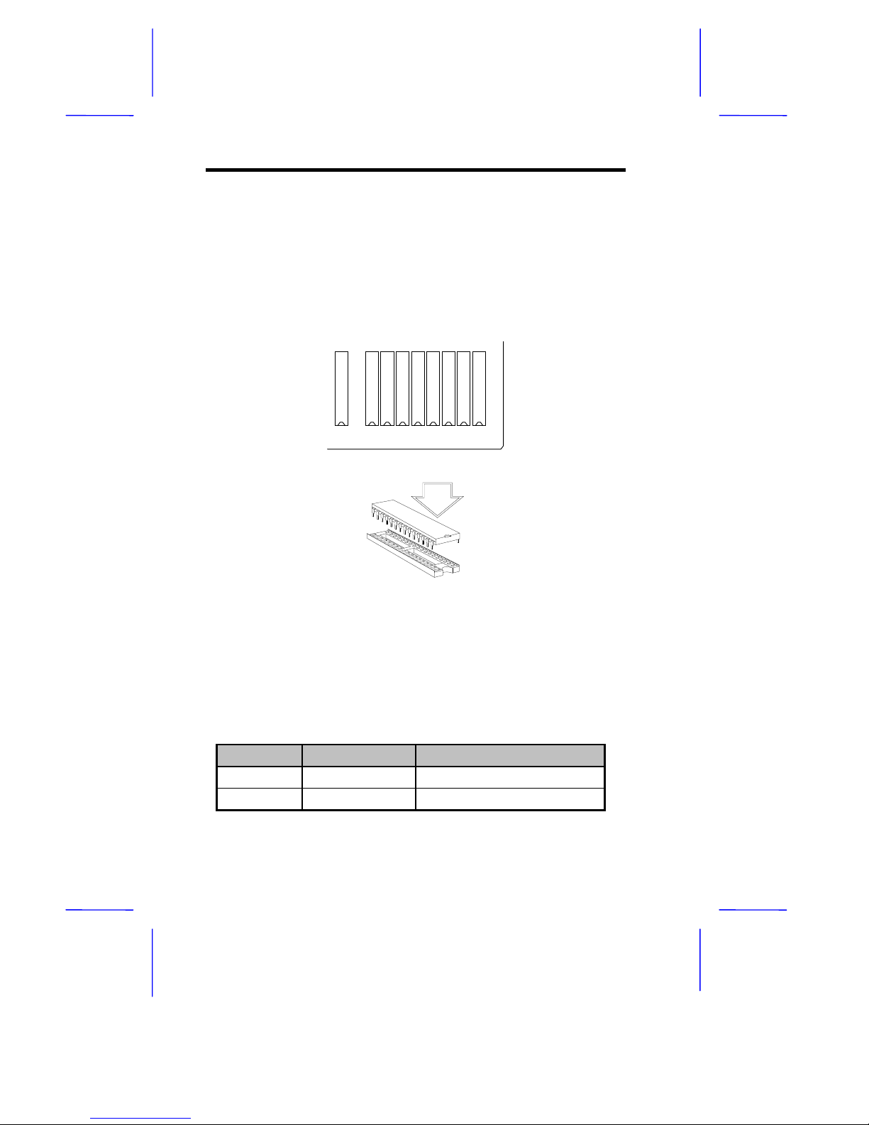
1. Locate the cache sockets on the system board. See Figure 1-1.
2. Align the cut edge of the chip with the cut edge of the cache
sockets. See Figure 1-8.
TAG U56 U57 U58 U59 U60 U61 U62 U63
Figure 1-8 Installing Cache
3. Gently but firmly insert a 32 Kb x 8, 15 ns SRAM chip into each of
the sockets. Be careful not to bend any pins. Table 1-6 lists the
cache size options and the corresponding chip configuration.
Table 1-6 Cache Size Options and Chip Locations
Cache Size SRAM Type Location
128 KB 32 Kb x 8 x 5 pcs
TAG, U56, U58, U60, U62
256 KB 32 Kb x 8 x 9 pcs
TAG, U56 to U63
Page 17

System Board 1-17
The SRAM must have an access speed of 15
nanoseconds.
Make sure that you set the jumpers properly.
See section 1.4.
1.10 Post-installation Instructions
Always observe the following:
1. See to it that the components are inst alled according to the stepby-step instructions in their respective sections.
2. Make sure you have set all the required jumpers before you
proceed. See section 1.4 for the correct jumper settings.
3. Replace any expansion boards or peripherals that you removed
earlier.
4. Replace the system cover.
5. Connect the necessary cables and turn on the system.
Page 18

1-18 User’s Guide
1.11 Power-Management Feature
The mainboard incorporates the lates t power-c ons ervation tec hnology.
However, to take advantage of its energy-saving capabilities, the
mainboard must have an Intel SL-Enhanced or a power-saving CPU.
The Power-Management feature allows you to monitor system activity.
System activity refers to any action involving one or more of the
following devices: keyboard, mouse, disk ette drives, f ixed dis k drives,
connected peripherals, or video memory. If no activity is detected
within a specified period of time (the inactivity time-out), the system
switches to one of the power-saving modes to conserve energy.
The Setup utility allows you to specify the
inactivity time-out. Refer to Section 2.4 for
more information on the power-saving
configuration.
The power-management function does not
work when the cursor is emulated by
software such as Winword, ETU 3.1
(Chinese system), DOSV (Japanese
system), etc.
The system supports four power-management modes:
•
Monitor power-saving mode
•
IDE fixed disk standby mode
•
Standby mode
•
Suspend mode
MONITOR POWE R-SAVING MODE
The Monitor Power-Saving Mode offers a quick- resume power-saving
mode for VESA DPMS-com pliant VGA monitors. It allows temporary
power saving during operation.
Page 19

System Board 1-19
Set the independent power-management tim ers for the VESA DPMS
monitor. Valid values are from 1 to 15 minutes. Any video or I/O
action returns the system to full power.
IDE FIXED DISK STANDBY MODE
The IDE Fixed Disk Standby Mode offers a quick-resume powersaving mode for ATA-com pliant IDE fixed disk s. It is allows tem porar y
power saving during operation.
Set the independent power-management timers for the fixed disk.
Valid values are from 1 to 15 m inutes. In this mode, the fixed disk
spin motor is shut off. Any fixed disk activity returns the fixed disk to
normal speed within 3 to 5 seconds (depending on the fixed disk in
use).
SYSTEM STANDBY MODE
This is a fast-on power-saving mode that allows quick-resume
response time and at the sam e time lowers power-consum ption. It is
most suitable for users who want power-saving features but need the
PC to resume normal operation quickly.
Set the Standby Mode timer to a value from 2 to 120 m inutes. W hen
the system enters Standby mode, the turbo LED light on the front
panel starts to blink. Any mouse/keyboard or I/O action enables the
system to exit Standby mode and return quickly to normal operation.
SUSPEND MODE
This mode sends the CPU and all peripherals into the lowest
power-consumption mode possible. However, it tak es a longer time
for the system to resume normal operation depending on the fixed disk
drive and monitor type in use.
Page 20
1-20 User’s Guide
Set the Suspend Mode timer to a value from 2 to 120 minutes, or
activate the Suspend/Resume button. In Suspend m ode, the turbo
LED light on the front panel blinks at a rate slower than when the
system is in the Standby mode. Activating the Suspend/Resume
button produces two beeps as the system enters the suspend mode.
Any keyboard/mouse or I/O action resumes full power.
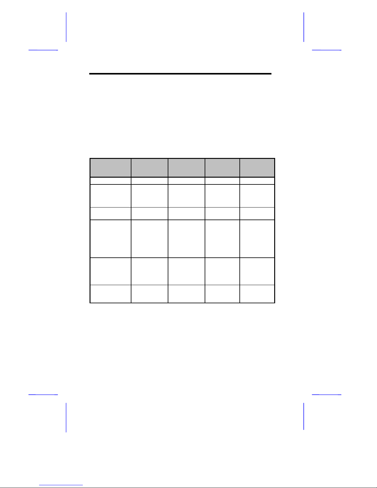
Power-Management Modes
Table 1-7 Power-Management Modes
Monitor
Power-
Saving Mode
IDE Fixed
Disk Standby
Mode
System
Standby
Mode
System
Suspend
Mode
Monitor Mode
Suspend No effect Off On
IDE HDD
Status
No effect Standby
mode
Spindle
motor off
Standby
mode
Spindle
motor off
Standby
mode
Spindle
motor off
CPU/System
Status
Normal Normal Normal CPU clock
stopped
Entry Mode
Device idle
timer time-out
(1 - 15 min)
Device idle
timer time-out
(1 - 15 min)
System
standby timer
time-out
(2 - 120 min)
System
Suspend
timer time-out
(2 - 120 min)
or Suspend
button
pushed
Resume Mode
Device
activated
Any fixed disk
access
Any system
event
Keyboard/
mouse or
Resume
button
pushed
Resume
Recovery
Time
3 - 5 sec 3 - 5 sec 7 - 10 sec 7 - 10 sec
Application Condition
You must disable the Suspend mode f or LAN work stations. Since the
CPU is stopped in Suspend mode, this pr events the workstation from
responding to LAN requests. Thus, the system is considered
disconnected from the network.
Page 21

System Board 1-21
1.12 Advanced Power Management (APM)
This system features the APM standard designed to further reduce
system power consumption. APM is a power-management approach
developed jointly by Microsoft and Intel. An increasing number of
software applications support APM to take advantage of the powersaving features and offer greater system availability without affecting
performance.
To use the APM feature under the Windows environment, run the
Windows Setup and select the MS-DOS System with APM as your
computer type in the System Information m enu. Refer to the Windows
manual for more information.
You can use the APM feature under the DOS environment by including
the POWER.EX E commmand in the CO NFIG.SYS file. See the MSDOS manual for more instructions on how to edit the CONFIG.SYS
file. For more information about APM, type
HELP POWER.EXE.
If you enable the Power-Saving mode in
Setup without installing the APM under DOS
or Windows, the system time and date do not
display the correct settings after the system
returns to normal operation from Standby or
Suspend mode. To update the time and
date, reboot the system. Connect the APM
to avoid this problem.
1.13 Intel SL-Enhanced CPU
The Intel SL-Enhanced microprocessors support the System
Management Mode (SMM). In SMM mode, the CPU saves the current
status to the memory and shuts down the CPU internal clock after a
specified period of inactivity. This reduces the system power
consumption from 10 watts to 0.02 watts.
Page 22
1-22 User’s Guide
1.14 VESA DPMS
The Video Electronics Standard Association (VESA) proposed the
Display Power-Management Signaling (DPMS) standard com binations
of horizontal and vertical synchronization signals for the PC-VGA
monitor. Its purpose is to comply with the U.S. Environmental
Protection Agency (EPA) requirements.
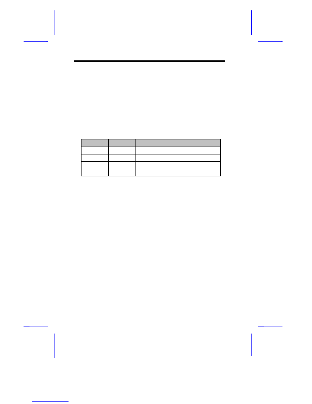
Table 1-8 lists the different VESA DPMS modes and their functions.
Table 1-8 VESA DPMS Modes
H-Sync V-Sync Monitor Mode Function
Off Off Off No operation
On Off Suspend Power-saving
Off On Standby Screen-saving
On On On Normal operation
Page 23

System Board 1-23
1.15 Error Messages
In the event that you receive an error message, do not continue using
the computer. Note the mess age and take corrective ac tion at once.
This section describes the different types of error messages and
suggests corrective measures.
There are two general types of error messages:
•
Software
•
System
1.15.1 Software Error Messages
Software error messages are returned by your operating system or
application. These messages typically appear after you boot the
operating system or when you run your applications. If you receive
this type of message, consult your application or operating system
manual for help.
1.15.2 System Error Messages
A system error message indicates a problem with the computer itself.
These messages normally appear during the power-on self-test,
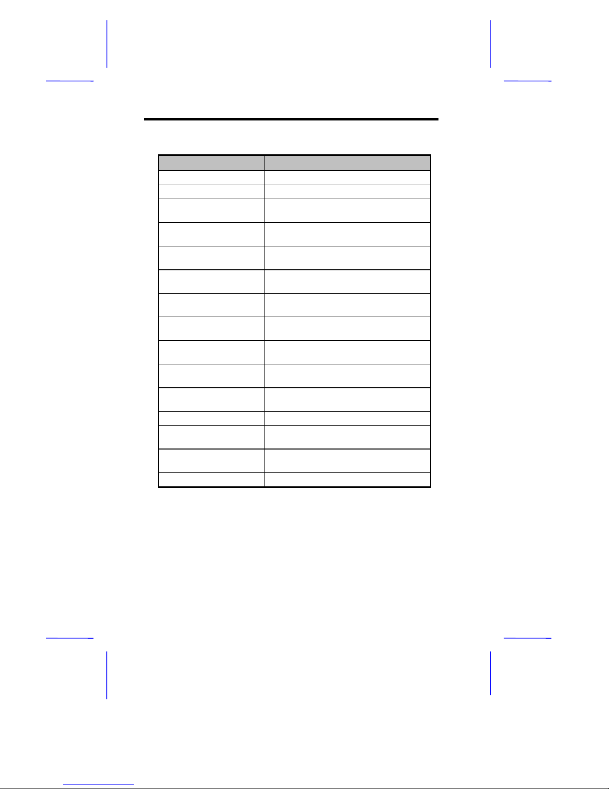
before the operating system prompt appears. Table 1-9 lists the
system error messages in alphabetical order.
Page 24
1-24 User’s Guide
Table 1-9 System Error Messages
Error Message Corrective Action
Bad CMOS Battery Replace battery. Contact your dealer.
CMOS Checksum Error Run Setup.
Diskette Drive Controller
Error
Check and connect the cable to the
diskette drive or controller.
Diskette Drive Error Diskette may be bad. If not, check the
diskette drive and replace if necessary.
DRAM Configuration
Error
Check and modify DRAM configuration
to agree with Table 1-5.
Equipment
Configuration Error
Run Setup.
Fixed Disk Controller
Error
Check and connect the cable to the
fixed disk drive or controller.
Fixed Disk 0 Error Check all cable connections. Check the
fixed disk and replace if necessary.
Fixed Disk 1 Error Check all cable connections. Check the
fixed disk and replace if necessary.
Fixed Disk 0 Extended
Type Error
Run Setup.
Fixed Disk 1 Extended
Type Error
Run Setup.
I/O Parity Error Contact your dealer.
Keyboard Error or No
Keyboard Connected
Check and connect the keyboard to the
system unit.
Keyboard Interface
Error
Contact your dealer.
Keyboard Locked Unlock the keyboard.
Page 25
System Board 1-25
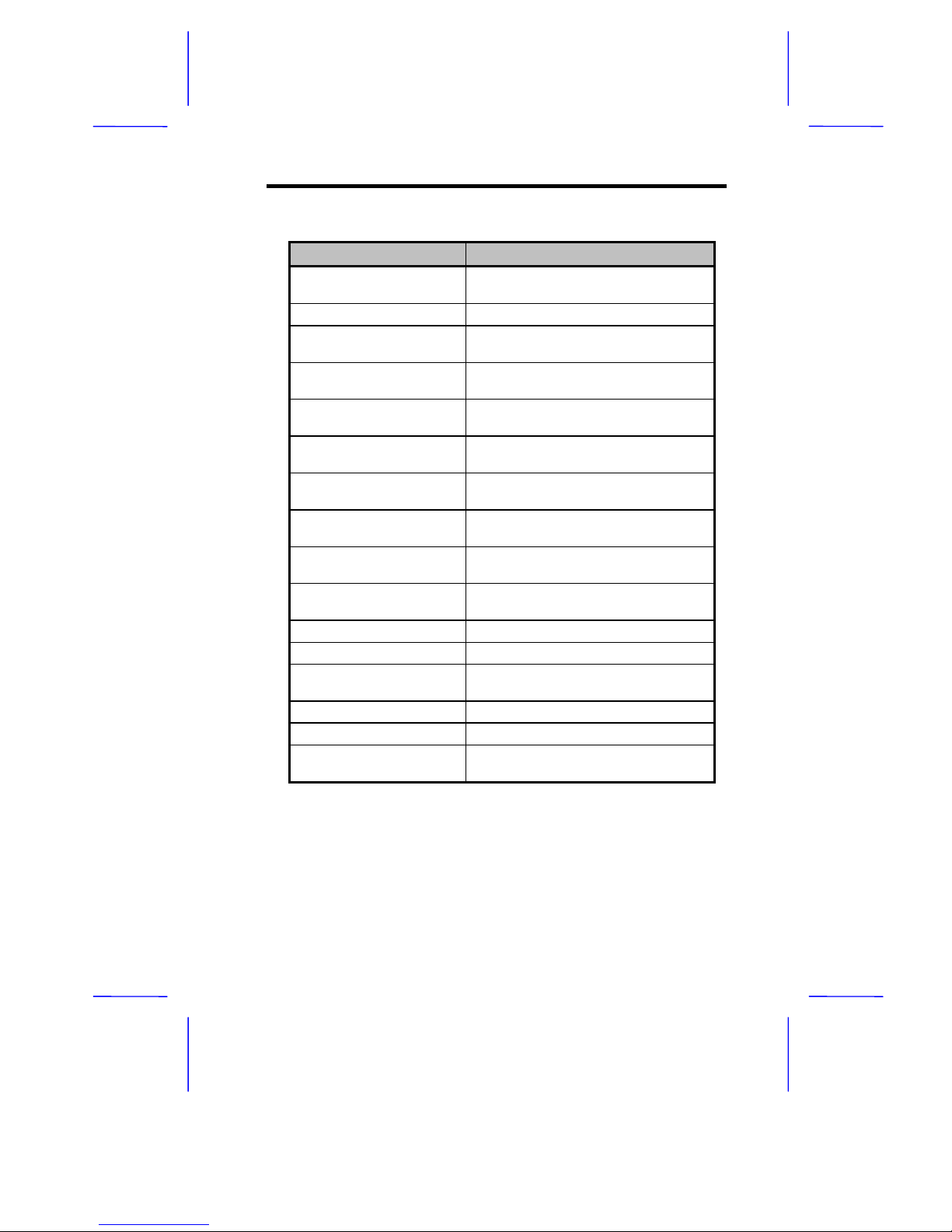
Table 1-9 System Error Messages (continued)
Error Message Corrective Action
Memory Error Check SIMMs on the system board.
Contact your dealer.
Memory Size Mismatch Run Setup.
Serial 1 Conflict Run Setup.
Disable onboard serial 1.
Serial 2 Conflict Run Setup.
Disable onboard serial 2.
Parallel Conflict Run Setup.
Disable onboard parallel port.
Pointing Device Error Check and connect the pointing
device. Contact your dealer.
Pointing Device Interface
Error
Contact your dealer.
Press F1 key to continue
or Ctrl-Alt-Esc for Setup
Press F1 or Ctrl-Alt-Esc.
Press F1 to Setup or
other key to continue
Press F1 and reconfigure the system.
Press Esc to turn off NMI,
any key to reboot
Press Esc to disregard NMI error.
Press any key to reboot the system.
Protected Mode Test Fail Contact your dealer.
RAM BIOS Error Contact your dealer.
RAM Parity Error Check SIMMs on system board or
contact your dealer.
Real Time Clock Error Run Setup.
Shadow RAM Fail Contact your dealer.
System Memory Address
Error
Check SIMMs on system board or
contact your dealer.
Page 26

1-26 User’s Guide
1.15.3 Correcting Error Conditions
As a general rule, the "Press F1 to continue" error mes sage is caus ed
by a configuration problem which can be easily corrected. An
equipment malfunction is more likely to cause a fatal error, i.e., an
error that causes complete system failure.
Here are some corrective measures for error conditions:
1. Run Setup. You must know the correct c onfiguration values for
your system before you enter Setup, which is why you should
write these values down when the system is correctly configured.
An incorrect Setup configuration is a major cause of power-on
error messages, especially for a new system.
2. Remove the system cover, following the directions in the system
housing installation guide. Check that the system board and any
expansion boards are set correctly.
3. If you cannot access a new disk, it may be because your disk is
not physically formatted. Physically format the disk using the
FDISK and FORMAT commands.
4. Check that all connectors and boards are secure. Consult the
system housing installation guide for assistance.
If you follow the corrective steps above and still receive an error
message, the cause may be an equipment malfunction.
If you are sure that your configuration values are correct and your
battery is in good condition, the problem may lie in a damaged or
defective chip. Contact an authorized service center for assistance.
 Loading...