

Page 1

Veriton 7600GTR/7600GT/7600V
Veriton 5600GT/5600V
Veriton 3600GT/3600V
Service Guide
Service guide files and updates are available
on the AIPG/CSD web; for more information,
please refer to http://csd.acer.com.tw
S E R V I C E C D PA R T N O . : V D . V 0 3 V 3 . 0 0 1 ‘‘
PRINTED IN TAIWAN
Page 2
Revision History
Please refer to the table below for the updates made on Veriton 7600GTR/GT/V, 5600GT/V and 3600GT/V
service guide.
Date Chapter Updates
II
Page 3

Copyright
Copyright © 2003 by Acer Incorporated. All rights reserved. No part of this publication may be reproduced,
transmitted, transcribed, stored in a retrieval system, or translated into any language or computer language, in
any form or by any means, electronic, mechanical, magnetic, optical, chemical, manual or otherwise, without
the prior written permission of Acer Incorporated.
Disclaimer
The information in this guide is subject to change without notice.
Acer Incorporated makes no representations or warranties, either expressed or implied, with respect to the
contents hereof and specifically disclaims any warranties of merchantability or fitness for any particular
purpose. Any Acer Incorporated software described in this manual is sold or licensed "as is". Should the
programs prove defective following their purchase, the buyer (and not Acer Incorporated, its distributor, or its
dealer) assumes the entire cost of all necessary servicing, repair, and any incidental or consequential
damages resulting from any defect in the software.
Acer is a registered trademark of Acer Corporation.
Intel is a registered trademark of Intel Corporation.
Pentium and Pentium IV are trademarks of Intel Corporation.
Other brand and product names are trademarks and/or registered trademarks of their respective holders.
III
Page 4
Conventions
The following conventions are used in this manual:
Screen messages Denotes actual messages that appear
on screen.
NOTE Gives bits and pieces of additional
information related to the current
topic.
WARNING Alerts you to any damage that might
result from doing or not doing specific
actions.
CAUTION Gives precautionary measures to
avoid possible hardware or software
problems.
IMPORTANT Reminds you to do specific actions
relevant to the accomplishment of
procedures.
IV
Page 5

Preface
Before using this information and the product it supports, please read the following general information.
1. This Service Guide provides you with all technical information relating to the BASIC CONFIGURATION
decided for Acer's "global" product offering. To better fit local market requirements and enhance product
competitiveness, your regional office MAY have decided to extend the functionality of a machine (e.g.
add-on card, modem, or extra memory capability). These LOCALIZED FEATURES will NOT be covered
in this generic service guide. In such cases, please contact your regional offices or the responsible
personnel/channel to provide you with further technical details.
2. Please note WHEN ORDERING FRU PARTS, that you should check the most up-to-date information
available on your regional web or channel. If, for whatever reason, a part number change is made, it will
not be noted in the printed Service Guide. For ACER-AUTHORIZED SERVICE PROVIDERS, your Acer
office may have a DIFFERENT part number code to those given in the FRU list of this printed Service
Guide. You MUST use the list provided by your regional Acer office to order FRU parts for repair and
service of customer machines.
V
Page 6

VI
Page 7

Table of Contents
Chapter 1 System Specifications 1
Overview . . . . . . . . . . . . . . . . . . . . . . . . . . . . . . . . . . . . . . . . . . . . . . . . . . . . . . . . . . 1
Features . . . . . . . . . . . . . . . . . . . . . . . . . . . . . . . . . . . . . . . . . . . . . . . . . . . . . . . . . . 2
Front Panel for Veriton 3600GT/V . . . . . . . . . . . . . . . . . . . . . . . . . . . . . . . . . . . . . . 3
Rear Panel for Veriton 3600GT/V . . . . . . . . . . . . . . . . . . . . . . . . . . . . . . . . . . . . . . . 5
Front Panel for Veriton 5600GT/V . . . . . . . . . . . . . . . . . . . . . . . . . . . . . . . . . . . . . . 7
Rear Panel for Veriton 5600GT/V . . . . . . . . . . . . . . . . . . . . . . . . . . . . . . . . . . . . . . . 9
Front Panel for Veriton 7600GTR/GT/V . . . . . . . . . . . . . . . . . . . . . . . . . . . . . . . . . 11
Rear Panel for Veriton 7600GTR/GT/V . . . . . . . . . . . . . . . . . . . . . . . . . . . . . . . . . 13
System Block Diagram . . . . . . . . . . . . . . . . . . . . . . . . . . . . . . . . . . . . . . . . . . . . . . 15
Keyboard . . . . . . . . . . . . . . . . . . . . . . . . . . . . . . . . . . . . . . . . . . . . . . . . . . . . . . . . 16
Hardware Specifications and Configurations . . . . . . . . . . . . . . . . . . . . . . . . . . . . . 18
Memory Channel Mode . . . . . . . . . . . . . . . . . . . . . . . . . . . . . . . . . . . . . . . . . . . . . 23
Chapter 2 System Utilities 26
Entering Setup . . . . . . . . . . . . . . . . . . . . . . . . . . . . . . . . . . . . . . . . . . . . . . . . . . . . 27
Product Information . . . . . . . . . . . . . . . . . . . . . . . . . . . . . . . . . . . . . . . . . . . . . . . . 28
Standard CMOS Features . . . . . . . . . . . . . . . . . . . . . . . . . . . . . . . . . . . . . . . . . . . 29
IDE Channel 0 Master/Slave and IDE Channel 1 Master/Slave Setup . . . . . . 31
Advanced BIOS Features . . . . . . . . . . . . . . . . . . . . . . . . . . . . . . . . . . . . . . . . . . . . 32
Advanced Chipset Features . . . . . . . . . . . . . . . . . . . . . . . . . . . . . . . . . . . . . . . . . . 35
Integrated Peripherals . . . . . . . . . . . . . . . . . . . . . . . . . . . . . . . . . . . . . . . . . . . . . . 37
Power Management Setup . . . . . . . . . . . . . . . . . . . . . . . . . . . . . . . . . . . . . . . . . . . 40
PnP/PCI Configurations . . . . . . . . . . . . . . . . . . . . . . . . . . . . . . . . . . . . . . . . . . . . . 43
PC Health Status . . . . . . . . . . . . . . . . . . . . . . . . . . . . . . . . . . . . . . . . . . . . . . . . . . 45
Frequency Control . . . . . . . . . . . . . . . . . . . . . . . . . . . . . . . . . . . . . . . . . . . . . . . . . 46
Load Optimized Settings . . . . . . . . . . . . . . . . . . . . . . . . . . . . . . . . . . . . . . . . . . . . . 47
System Security . . . . . . . . . . . . . . . . . . . . . . . . . . . . . . . . . . . . . . . . . . . . . . . . . . . 48
Set Supervisor Password . . . . . . . . . . . . . . . . . . . . . . . . . . . . . . . . . . . . . . . . 48
Set User Password . . . . . . . . . . . . . . . . . . . . . . . . . . . . . . . . . . . . . . . . . . . . . 49
Bypassing the Password . . . . . . . . . . . . . . . . . . . . . . . . . . . . . . . . . . . . . . . . . 49
Save & Exit Setup . . . . . . . . . . . . . . . . . . . . . . . . . . . . . . . . . . . . . . . . . . . . . . . . . . 51
Exit Without Saving . . . . . . . . . . . . . . . . . . . . . . . . . . . . . . . . . . . . . . . . . . . . . . . . . 52
Intel Serial ATA RAID Introduction . . . . . . . . . . . . . . . . . . . . . . . . . . . . . . . . . . . . . 53
ATA Operate Mode . . . . . . . . . . . . . . . . . . . . . . . . . . . . . . . . . . . . . . . . . . . . . 53
RAID BIOS Configuration . . . . . . . . . . . . . . . . . . . . . . . . . . . . . . . . . . . . . . . . . . . . 56
Chapter 3 Machine Disassembly and Replacement 64
General Information . . . . . . . . . . . . . . . . . . . . . . . . . . . . . . . . . . . . . . . . . . . . . . . . 65
Before You Begin . . . . . . . . . . . . . . . . . . . . . . . . . . . . . . . . . . . . . . . . . . . . . . 65
Disassembly Procedure Flowchart . . . . . . . . . . . . . . . . . . . . . . . . . . . . . . . . . . . . . 66
Disassembling the Veriton 7600GTR/GR/V . . . . . . . . . . . . . . . . . . . . . . . . . . . . . . 69
Disassembling the Veriton 5600GR/V . . . . . . . . . . . . . . . . . . . . . . . . . . . . . . . . . . 76
Disassembling the Veriton 3600GR/V . . . . . . . . . . . . . . . . . . . . . . . . . . . . . . . . . . 82
Chapter 4 Troubleshooting 90
Power-On Self-Test (POST) . . . . . . . . . . . . . . . . . . . . . . . . . . . . . . . . . . . . . . . . . . 91
POST Error Messages List . . . . . . . . . . . . . . . . . . . . . . . . . . . . . . . . . . . . . . . . . . . 97
Error Symptoms List . . . . . . . . . . . . . . . . . . . . . . . . . . . . . . . . . . . . . . . . . . . . . . . . 99
Undetermined Problems . . . . . . . . . . . . . . . . . . . . . . . . . . . . . . . . . . . . . . . . . . . . 103
Chapter 5 Jumper and Connector Information 104
Jumper and Connector Description . . . . . . . . . . . . . . . . . . . . . . . . . . . . . . . . . . . 104
Jumper and Connector Description . . . . . . . . . . . . . . . . . . . . . . . . . . . . . . . 105
VII
Page 8

Table of Contents
Jumper Setting . . . . . . . . . . . . . . . . . . . . . . . . . . . . . . . . . . . . . . . . . . . . . . . 105
Main Board Layout . . . . . . . . . . . . . . . . . . . . . . . . . . . . . . . . . . . . . . . . . . . . . . . . 106
Chapter 6 FRU (Field Replaceable Unit) List 108
Veriton 7600GTR/GR/V Exploded Diagram . . . . . . . . . . . . . . . . . . . . . . . . . . . . . 109
Veriton 5600GR/V Exploded Diagram . . . . . . . . . . . . . . . . . . . . . . . . . . . . . . . . . 110
Veriton 3600GR/V Exploded Diagram . . . . . . . . . . . . . . . . . . . . . . . . . . . . . . . . . 111
Appendix A Model Definition and Configuration 121
Appendix B Test Compatible Components 122
Microsoft Windows XP Environment Test . . . . . . . . . . . . . . . . . . . . . . . . . . . . . . . 123
Appendix C Online Support Information 126
VIII
Page 9

Table of Contents
IX
Page 10

System Specifications
Overview
The Veriton 7600GTR/7600GT/7600V, 5600GT/5600V and 3600GT/3600V supports Intel® Pentium 4
processor with Hyper-Threading (HT) Technology, adding intelligence to help manage and prioritize multiple
threads received from the microprocessor.
This highly flexible and scalable solution meets a broad range of demanding computing needs. The 865G/
865GV chipsets offer high-bandwidth interfaces such as dual-channel DDR400 main memory, 800 MHz
system bus, integrated graphics controller with Intel Extreme Graphics 2 Technology, AGP8X Graphics (for
Intel 865G chipset), Intel Communication Streaming Architecture featuring a Dedicated Network Bus (DNB)
interface for wire-speed Gigabit Ethernet (GbE) and Hi-Speed USB 2.0 connectivity to ensure the flexibility and
performance you expect.
Chapter 1
Chapter 1 1
Page 11

Features
Performance
T Intel Pentium
T Intel Celeron
T Intel Hyper-Threading Technology supported on 3.06 GHz and higher Pentium
T Intel 865G + ICH5R (for VT7600GTR), Intel 865G + ICH5 (for VT7600GT/5600GT/3600GT), Intel
T Integrated VGA
T 8X AGP expansion slot (for Intel 865G chipset)
T DDR400/333/266 SDRAM, 4 DIMM slots, expandable to 4GB dual-channel memory
T Power management function
T CD-ROM, CD-RW, DVD-ROM, or DVD/CD-RW combo drive
T High-capacity, Enhanced-IDE hard disc
T Supports USB 2.0 high-performance peripherals
T Plug-and-Play (PnP) feature
Multimedia
T 3-D quality audio system via onboard audio controller
T Audio-in/Line-in, Audio-out/Line-out, Headphone-out, and Microphone-in interfaces
®
4 supporting FSB up to 800 MHz or
®
supporting FSB up to 400 MHz
865GV + ICH5 (for VT7600V/5600V/3600V) chipset
®
4 system
NOTE: The system has two microphone-in jacks (front and rear). However, you can not use both of them at
the same time. By default, your system enables the microphone-in jack in front and disables the one at the
back.
Connectivity
T Three 32-bit v2.3 Master PCI bus slots (support 3.3v/5v PCI bus interface)
T One AGP slot supports 8x/4x at 0.8V (AGP 3.0) or 4x at 1.5V (3.3V not supported) -- (for Intel
865G chipset)
T Two PS/2 interfaces for mouse and keyboard
T One serial port
T One parallel port
T One VGA port
T Eight Universal Serial Bus (USB) 2.0 ports (two internal, two on the front and four on the rear
panel)
T High-speed V92, 56K Fax/modem (optional)
T Broadcom 5705 10/100/1000MB Gigabit Ethernet LAN support with remote wake-up function
Expansion
T 3 PCI slots + 4 DIMM slots+ 1 AGP slot (for Intel 865G chipset)
T Upgradeable memory and hard disk
2 Chapter 1
Page 12
Front Panel for Veriton 3600GT/3600V
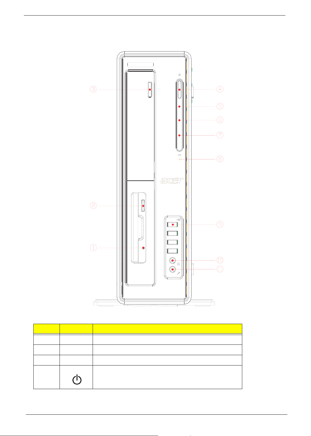
The computer’s front panel consists of the following:
Label Icon Description
1 Floppy drive LED
2 Floppy drive eject button
3 Optical drive Stop/Eject Button
4 Power button
Chapter 1 3
Page 13
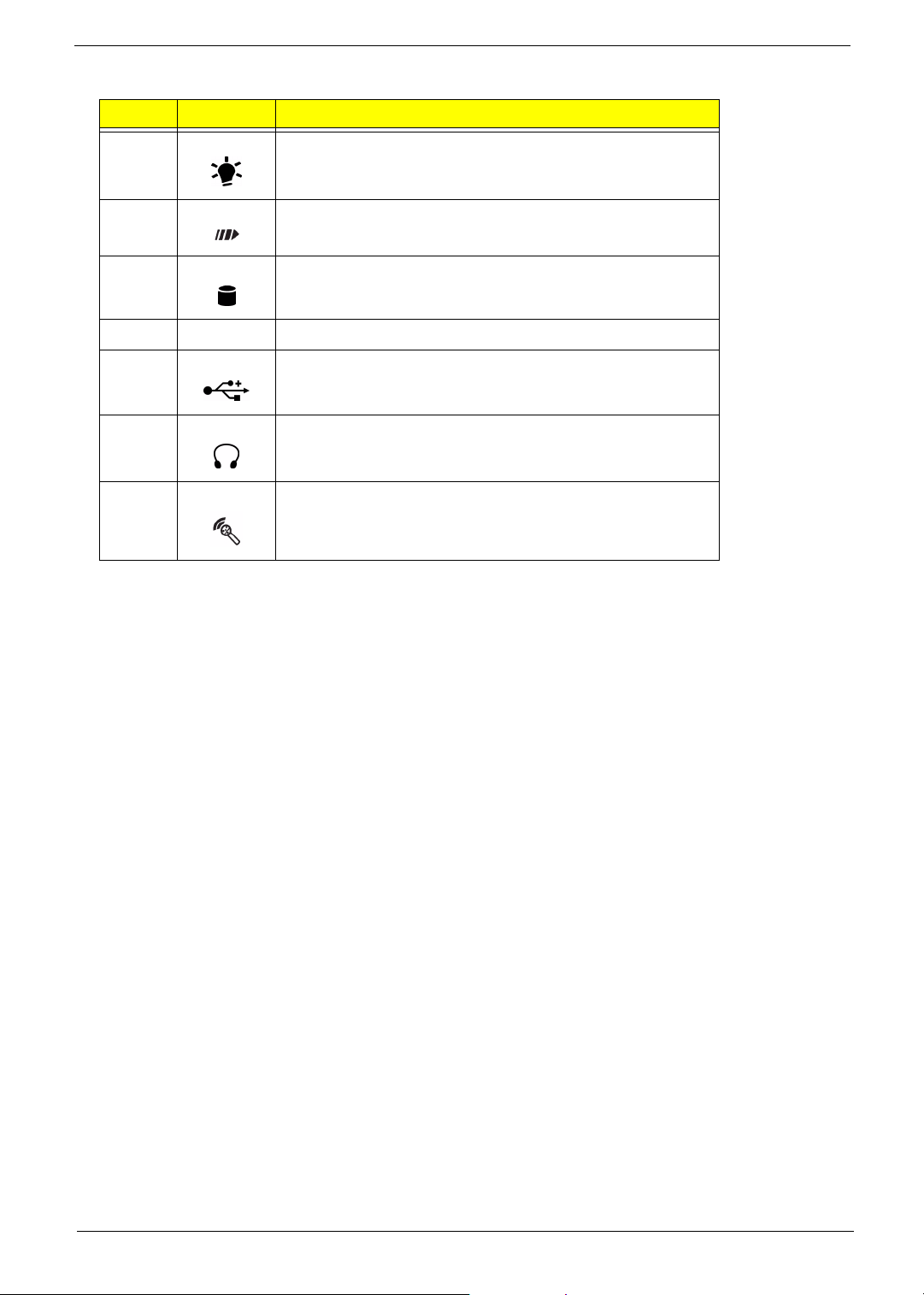
Label Icon Description
5 Power LED
6 LAN activity LED
7 Hard disk drive activity LED
8 One button recovery slot
9 USB ports
10 Headphone-out port
11 Microphone-in port (front)*
NOTE: *The system has two microphone-in ports (front and rear). However, you can not use both of them at
the same time. The default setting for your system enables the microphone-in port in front and disables
the one at the back.
4 Chapter 1
Page 14
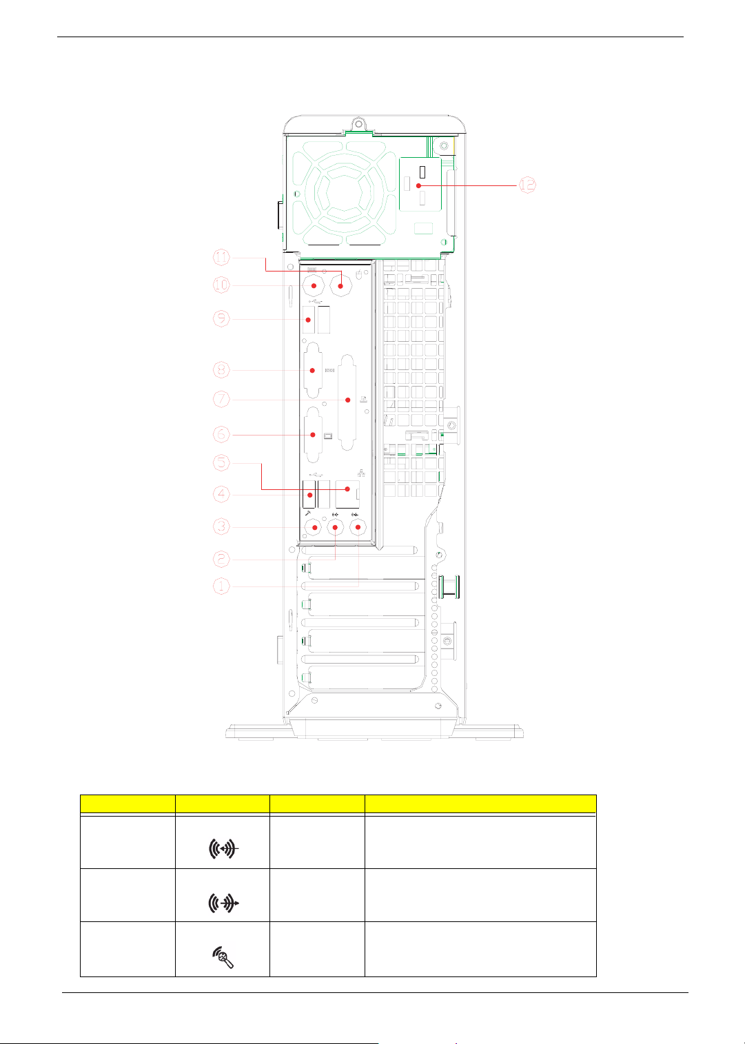
Rear Panel for Veriton 3600GT/3600V
Label Icon Color Description
1 Light blue Audio-in/Line-in jack
2 Lime Audio-out/Line-out jack
3 Pink Microphone-in jack (rear)*
Chapter 1 5
Page 15
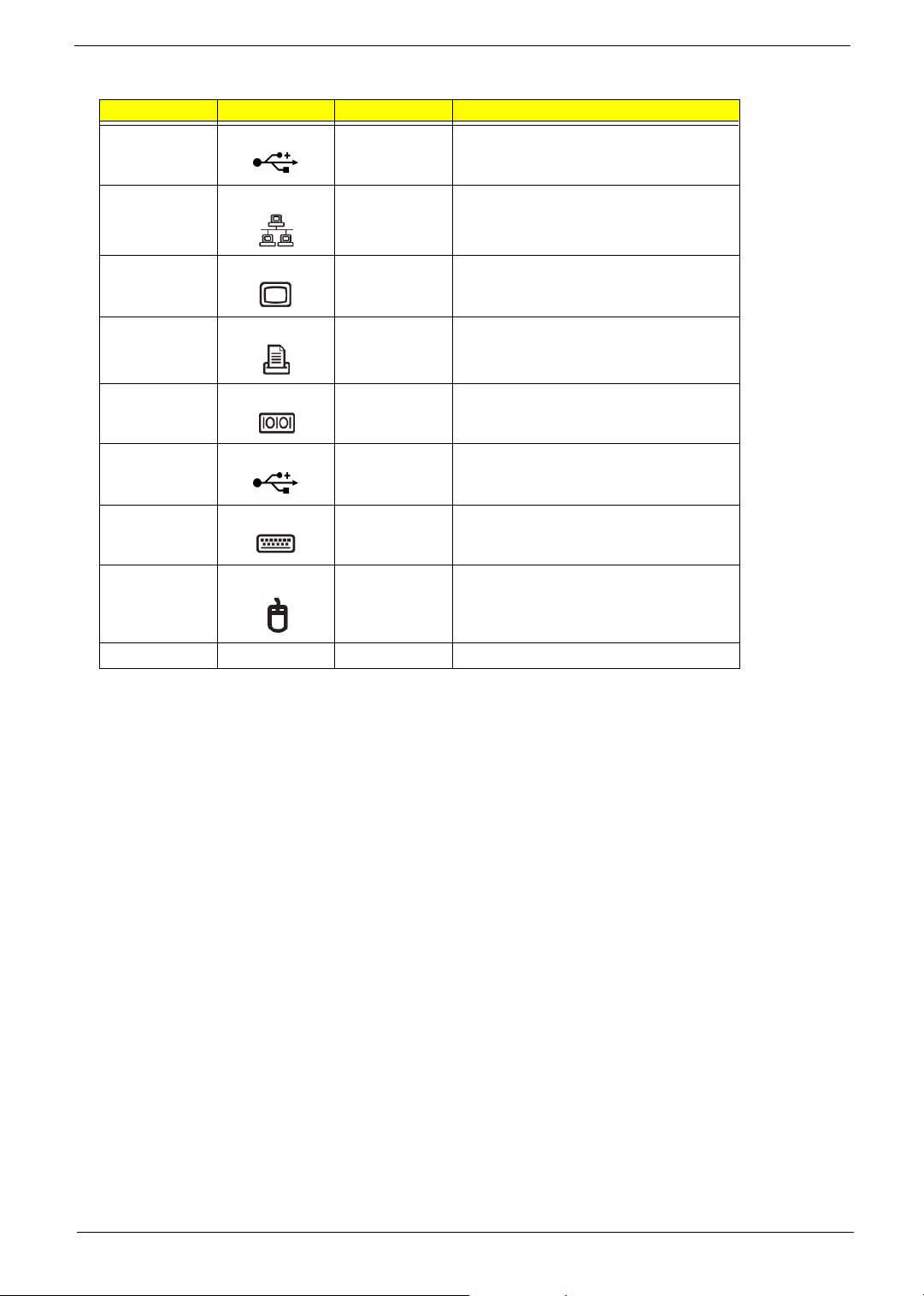
Label Icon Color Description
4 Black USB ports
5 White Network port
6 Blue CRT/LCD monitor port**
7 Burgundy Parallel/printer port
8 Teal or Turquoise Serial port
9 Black USB ports
10 Purple PS/2 keyboard port
11 Green PS/2 mouse port
12
Power cord socket
NOTE: * The system has two microphone-in ports (front and rear). However, you can not use both of them at
the same time. The default setting for your system enables the microphone-in port in front and disables
the one at the back.
NOTE: ** The CRT monitor port is automatically disabled when an add-on AGP VGA card is installed into the
system (for Intel 865G chipset). Connect the monitor to the VGA port instead.
6 Chapter 1
Page 16
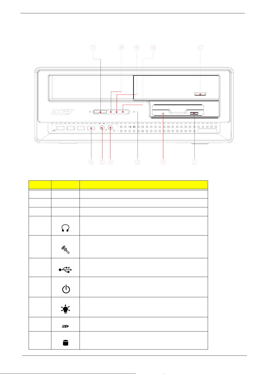
Front Panel for Veriton 5600GT/5600V
The computer’s front panel consists of the following:
Label Icon Description
1 Floppy drive eject button
2 Floppy drive LED
3 One button recovery slot
4 Headphone-out port
5 Microphone-in port (front)*
6 USB ports
7 Power button
8 Power LED
9 LAN activity LED
10 Hard disk drive activity LED
Chapter 1 7
Page 17
Label Icon Description
11 Optical drive Stop/Eject Button
NOTE: *The system has two microphone-in ports (front and rear). However, you can not use both of them at
the same time. The default setting for your system enables the microphone-in port in front and disables
the one at the back.
8 Chapter 1
Page 18
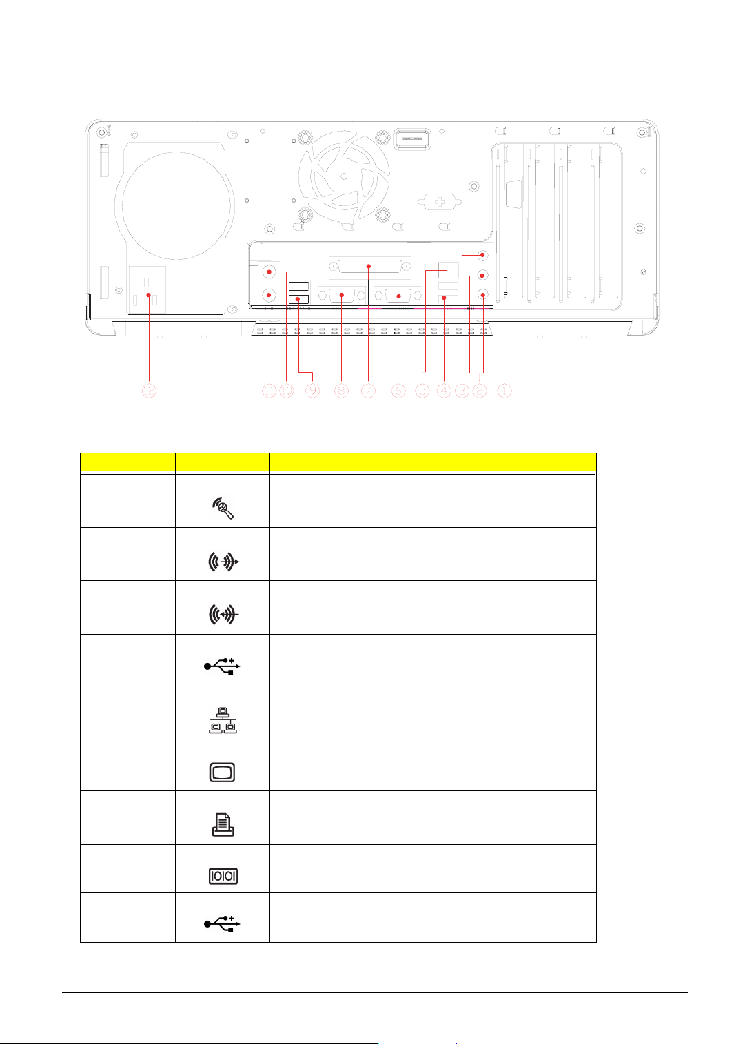
Rear Panel for Veriton 5600GT/5600V
Label Icon Color Description
1 Pink Microphone-in jack (rear)*
2 Lime Audio-out/Line-out jack
3 Light blue Audio-in/Line-in jack
4 Black USB ports
5 White Network port
6 Blue CRT/LCD monitor port**
7 Burgundy Parallel/printer port
8 Teal or Turquoise Serial port
9 Black USB ports
Chapter 1 9
Page 19
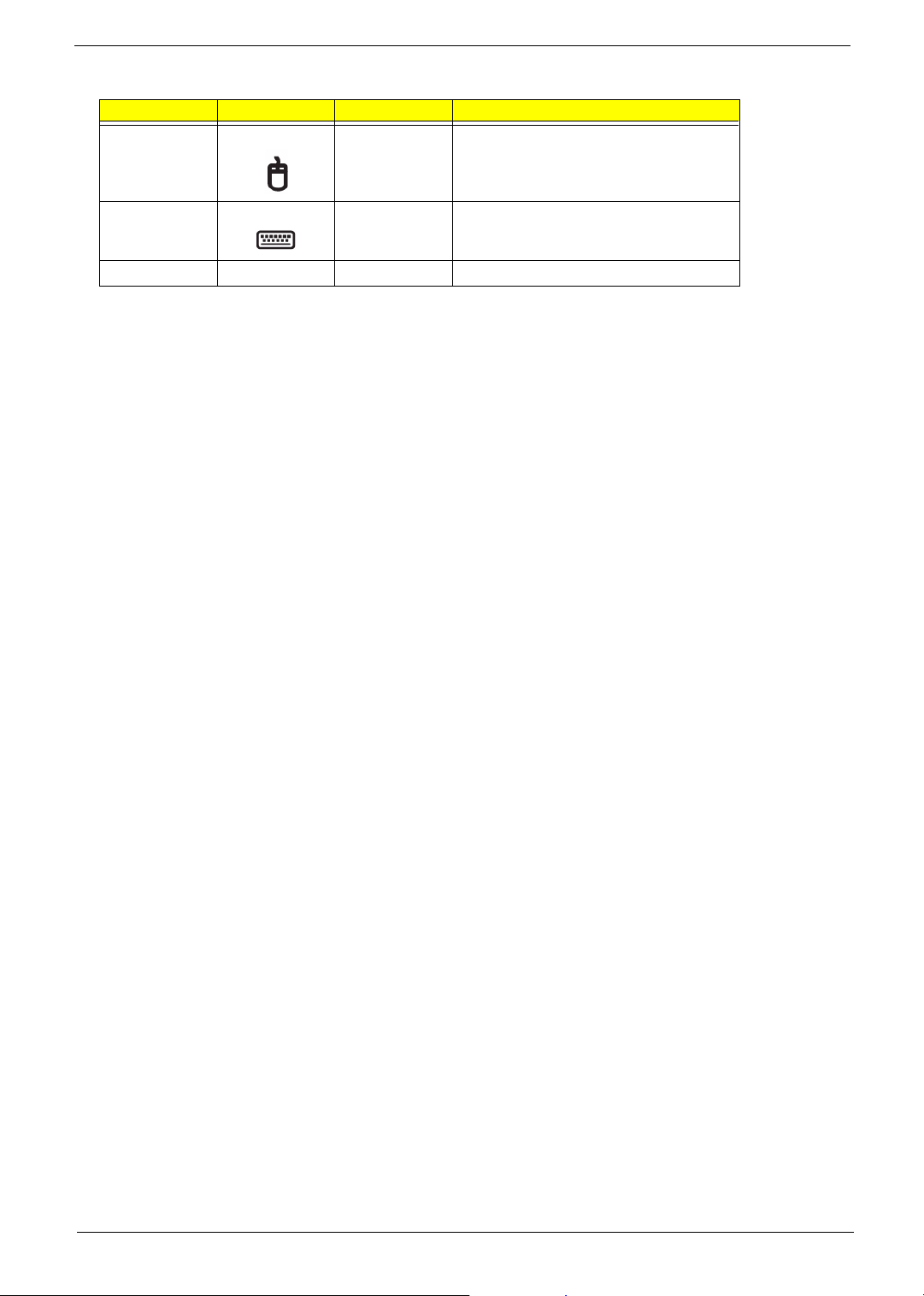
Label Icon Color Description
10 Green PS/2 mouse port
11 Purple PS/2 keyboard port
12
Power cord socket
NOTE: * The system has two microphone-in ports (front and rear). However, you can not use both of them at
the same time. The default setting for your system enables the microphone-in port in front and disables
the one at the back.
NOTE: ** The CRT monitor port is automatically disabled when an add-on AGP VGA card is installed into the
system (for Intel 865G chipset). Connect the monitor to the VGA port instead.
10 Chapter 1
Page 20
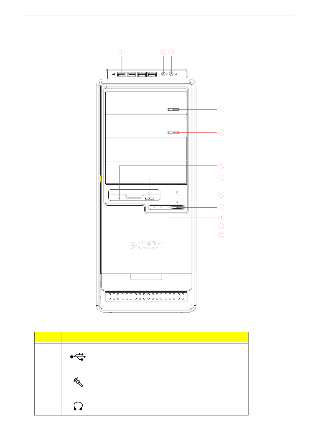
Front Panel for Veriton 7600GTR/7600GT/7600V
The computer’s front panel consists of the following:
Label Icon Description
1 USB ports
2 Microphone-in port (front)*
3 Speak-out/line-out port
Chapter 1 11
Page 21
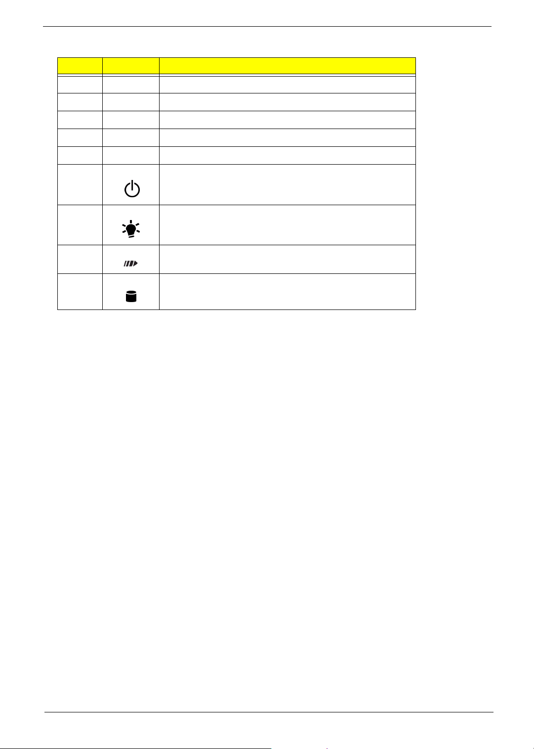
Label Icon Description
4 Optical drive Stop/Eject Button
5 Optical drive Stop/Eject Button
6 Floppy drive LED
7 Floppy drive eject button
8 One button recovery slot
9 Power button
10 Power LED
11 LAN activity LED
12 Hard disk drive activity LED
NOTE: *The system has two microphone-in ports (front and rear). However, you can not use both of them at
the same time. The default setting for your system enables the microphone-in port in front and disables
the one at the back.
12 Chapter 1
Page 22
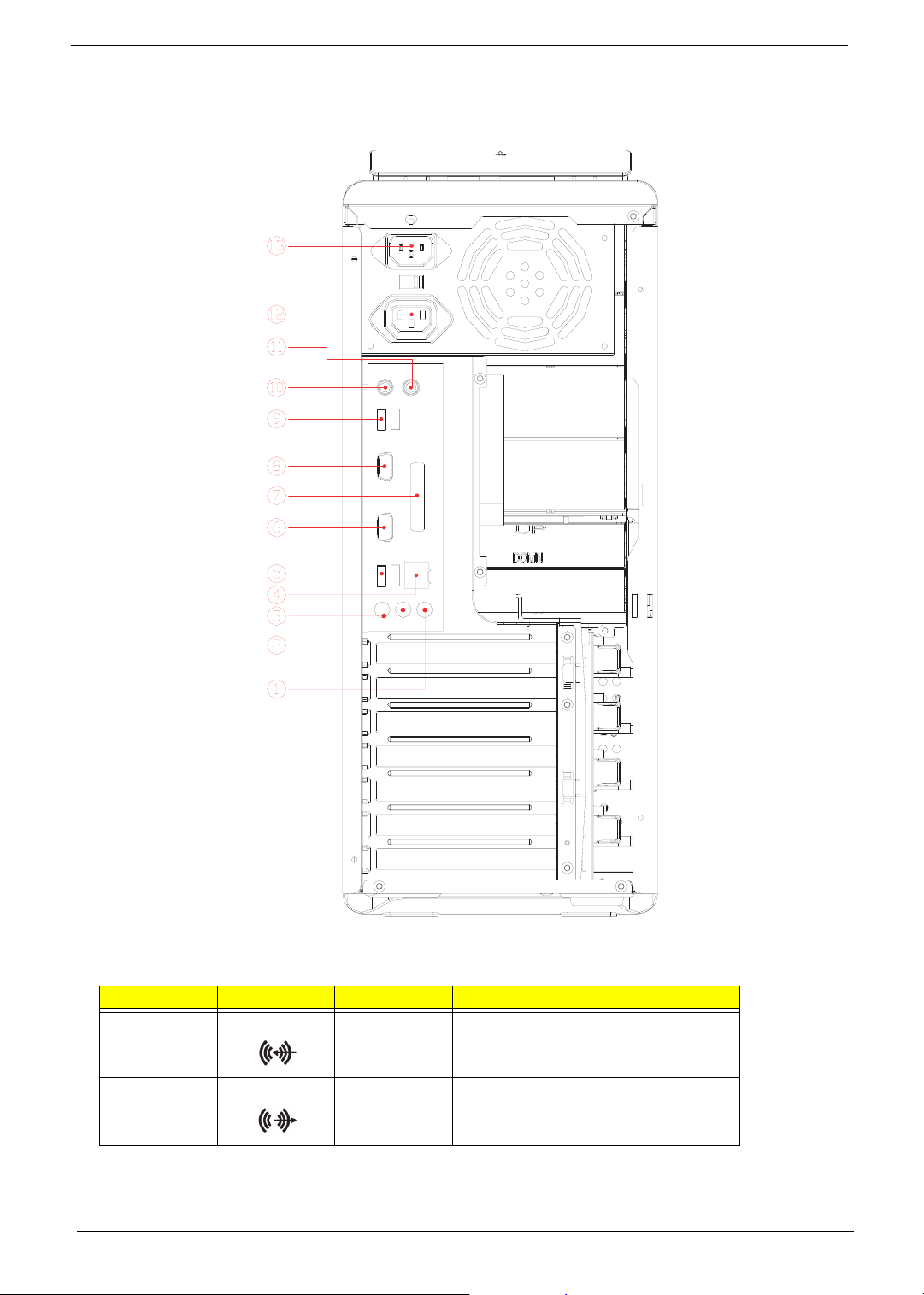
Rear Panel for Veriton 7600GTR/7600GT/7600V
Label Icon Color Description
1 Light blue Audio-in/Line-in jack
2 Lime Audio-out/Line-out jack
Chapter 1 13
Page 23
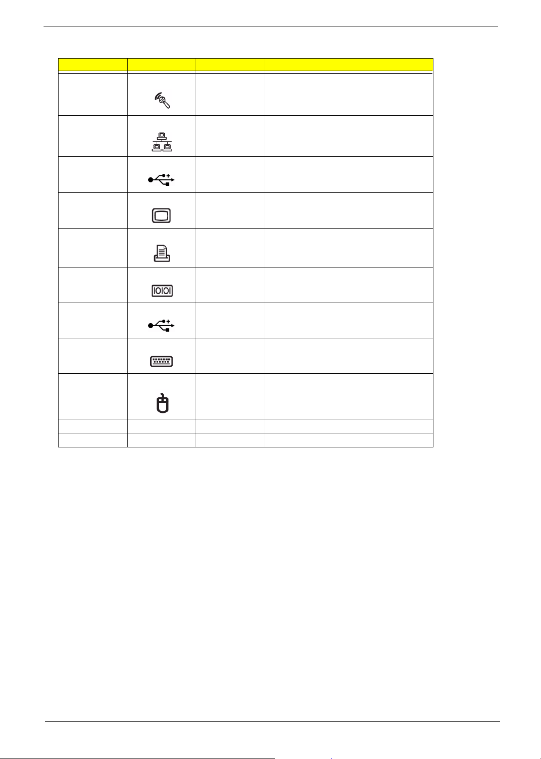
Label Icon Color Description
3 Pink Microphone-in jack (rear)*
4 White Network port
5 Black USB ports
6 Blue CRT/LCD monitor port**
7 Burgundy Parallel/printer port
8 Teal or Turquoise Serial port
9 Black USB ports
10 Purple PS/2 keyboard port
11 Green PS/2 mouse port
12 Power cord socket
13 Power cord socket
NOTE: * The system has two microphone-in ports (front and rear). However, you can not use both of them at
the same time. The default setting for your system enables the microphone-in port in front and disables
the one at the back.
NOTE: **The CRT monitor port is automatically disabled when an add-on AGP VGA card is installed into the
system. Connect the monitor to the VGA port instead.
14 Chapter 1
Page 24
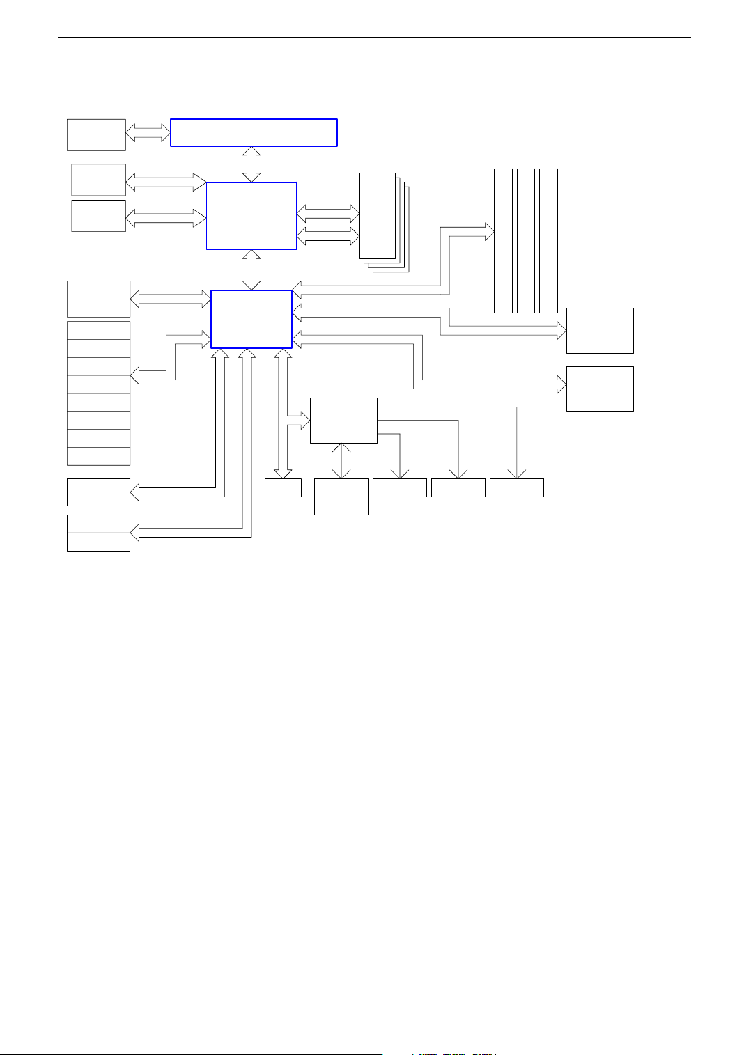
System Block Diagram
VRM 10
ST L6710
2-Phase PWM
AGP 1.5V
Connector
Analog
Video
Out
IDE Primary
IDE Secondary
USB Port 0
USB Port 1
USB Port 2
USB Port 3
USB Port 4
USB Port 5
USB Port 6
USB Port 7
AC'97 Codec
Serial ATA 0
Serial ATA 1
4X/8X
UltraDMA 33/66/100
USB
AC'97 Link
Serial ATA
Intel mPAG478B Processor
FSB
Springdale
HUB
Link
ICH5R
LPC Bus
Flash
64bit DDR
Channel 1
64bit DDR
Channel 2
LPC SIO
SMSC
47M192
Keyboard
Mouse
4 DDR
DIMM
Modules
(1+1)
PCI BUS
PCI BUS
PCI BUS
Floopy Parallel Serial
Block Diagram
PCI Slot 3
PCI Slot 2
PCI Slot 1
IEEE1394
TSB43AB23
LAN
BCM4401/5705
Chapter 1 15
Page 25
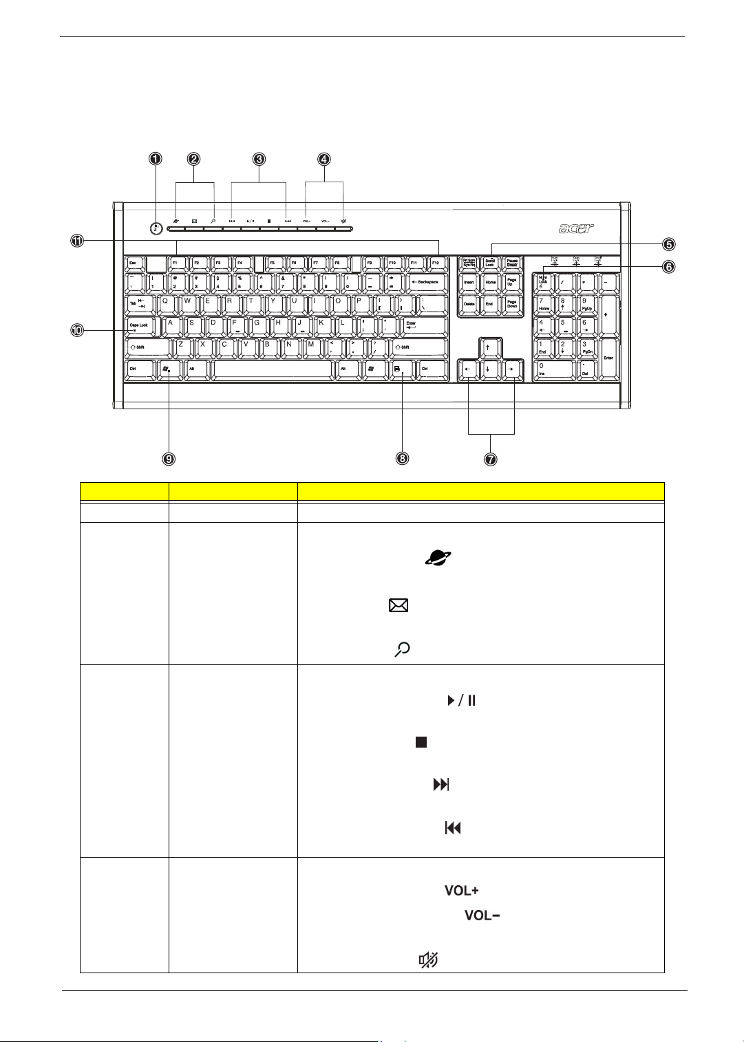
Keyboard
The keyboard has full-sized keys that include separate cursor keys, two Windows keys, and twelve function
keys.
Lable Key Description
1
2
3 Multimedia keys
4
Sleep button
Internet/E-mail/Search
keys
Volume control/Mute
keys
Puts the system to sleep when pressed this button.
Consist of three buttons:
• Web browser : launches the browser application that
came bundled with your system.
• E-mail : launches the e-mail application that came bun-
dled with your system.
• Search : opens a search window.
Allow you to do the following:
• Play/Pause button : press to start playing the audio
track or video file. Press again to pause.
• Stop button : press to stop playing the audio track or video
file.
• Forward button : press to skip forward to the next track or
file and start playing.
• Backward button : press to skip backward to the previous
track or file and start playing.
Allow you to do the following:
• Volume up button : press to increase audio volume.
• Volume down button : press to decrease audio volume.
• Mute button : toggle sound on/off.
16 Chapter 1
Page 26
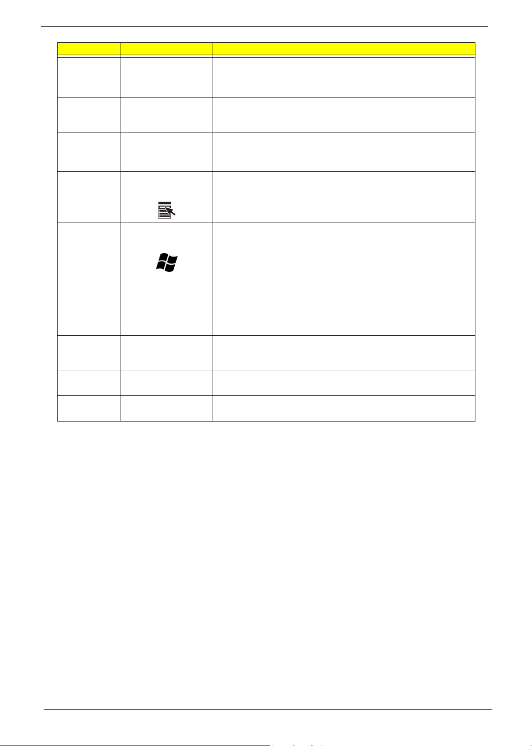
Lable Key Description
5
6
Scroll Lock Key
[
Num Lock Key
When activated, the screen moves one line up or down when you press
the up arrow or down arrow respectively. Take note that
work with some applications.
When activated, the keypad is set to numeric mode, i.e., the keys function
as a calculator (complete with arithmetic operators such as +, -, * and /).
]
7
8
Cursor keys
Application key
Also called arrow keys, let you move the cursor around the screen. They
serve the same function as the arrow keys on the numeric keypad when
the
] is toggled off.
Opens the applications context menu (same function as clicking the right
button of the mouse).
[may not
9
10
11
Windows logo key Start button. Combinations with this key perform special functions, such
as:
• Windows + Tab : Activates the next Taskbar button
• Windows + E : Explore My Computer
• Windows + F : Find Document
• Windows + M : Minimize All
j + Windows + M : Undo Minimize All
•
• Windows + R : Displays Run dialog box
Caps lock
@
Function keys The function keys, F1 ~ F12, let you perform specific functions, depending
Palm rest
When activated, all alphabetic characters typed appear in uppercase
(same function as pressing
on the application that uses them.
The detachable palm rest provides you a comfortable place to rest your
hands while typing.
j + <letter>).
Chapter 1 17
Page 27
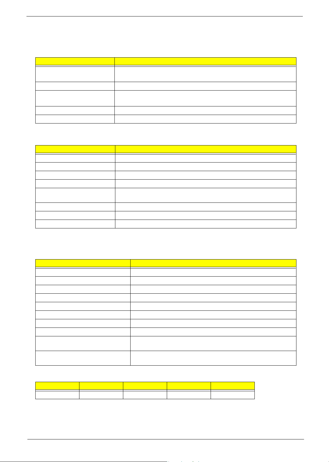
Hardware Specifications and Configurations
Processor
Item Specification
Type Intel® Pentium 4 1.8 ~ 3.2GHz FSB400/533/800MHz
Intel® Celeron 2.0 ~ 2.6GHz and above
Slot Socket 478
Speed Internal: 1.4 ~ 3.2GHz+
External: 400/533/800MHz Data Bus Frequency for Springdale-G.
Minimum operating speed 0 MHz (If Stop CPU Clock in Sleep State the BIOS Setup is set to Enabled.)
Voltage Processor voltage can be detected by the system without setting any jumper.
BIOS
Item Specification
BIOS code programmer Award
BIOS version V6.0
BIOS ROM type PLCC
BIOS ROM size 4MB
Support protocol PCI 2.1, APM1.2, DMI 2.00.1, E-IDE, ACPI 1.0, ESCD 1.03, ANSI ATA 3.0, PnP
Boot from CD-ROM feature Yes
Support to LS-120 drive Yes
Support to BIOS boot block feature Yes
1a, Bootable CD-ROM 1.0, ATAPI
NOTE: The BIOS can be overwritten/upgraded using the FLASH utility (AWDFLASH.EXE).
System Memory
Item Specification
Memory socket number 4 sockets
Support memory size per socket 128/256/512/1024MB
Support maximum memory size 4GB (4096MB)
Support memory type DDR SDRAM PC3200/PC2700/PC2100
Support memory speed DDR 400/ DDR 333/ DDR 266
Support memory voltage 2.5V
Support memory module package 184 -pin DIMM
Support to parity check feature Yes
Support to Error Correction Code (ECC)
feature.
Memory module combinations You can install memory modules in any combination as long as they match
No
the Memory Combination specifications.
Memory Combinations
DIMM 1 DIMM 2 DIMM3 DIMM4 To tal
128MB~1GB 128MB~1GB 128MB~1GB 128MB~1GB 128MB~4GB
NOTE: Please read “Memory Channel Mode” on page 19.
18 Chapter 1
Page 28
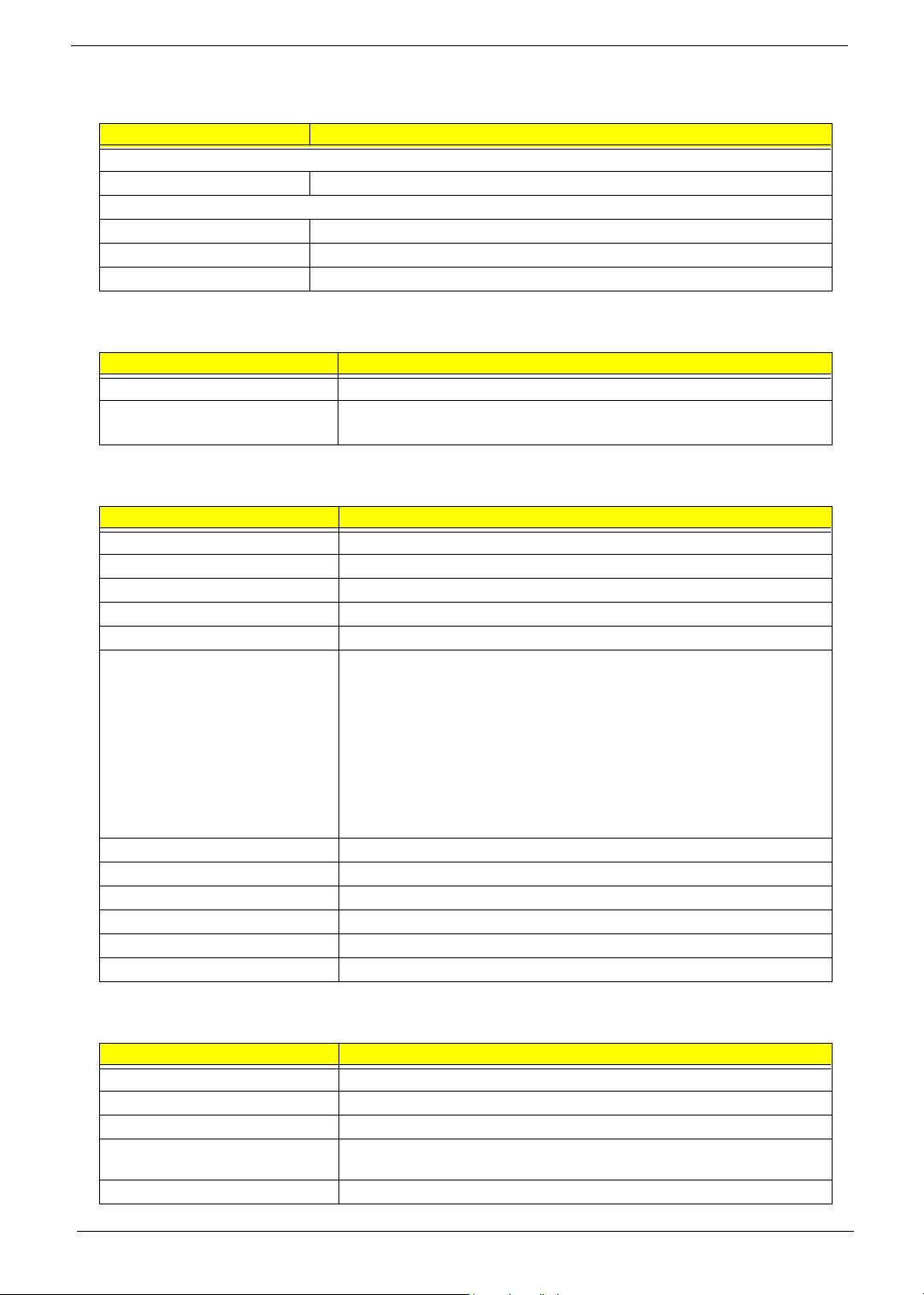
Cache Memory
Item Specification
First-Level Cache Configurations
Cache function control Enable/Disable by BIOS Setup (Advanced options)
Second-Level Cache Configurations: Below information is only applicable to system with installed Pentium 4 processor.
L2 Cache RAM size Pentium IV processor: 512 KB for Northwood
L2 Cache RAM speed The same with the processor core clock frequency
L2 Cache function control Enable/Disable by BIOS Setup
Video Interface
Item Specification
Video controller resident bus AGP bus
Video interface support
(for Intel 865G chipset)
8x/ 4x AGP Data Transfer
The AGP buffers operate only 0.8V/1.5V mode. (3.3V not supported)
Audio Interface
Item Specification
Audio controller Intel ICH5R/ICH5
Audio controller resident bus AC’97 link
Audio function control Enable/disable by BIOS Setup
Mono or stereo Stereo
Resolution 20 bits
Compatibility AC’97 2.1 compliant
Sound Blaster Pro compatible
Mixed digital and analog high performance chip
Enhanced stereo full duplex operation
High performance PCI audio accelerator
High-Quality ESFM music synthesizer
MPU-401(UART mode) interface for wavetable synthesizers and MIDI devices
Integrated game port
Meets PC 97/PC98 and WHQL specifications
Music synthesizer Yes
Sampling rate 44.1 KHz
MPU-401 UART support Yes
Microphone jack Supported On audio-I/O board (Front Panel/Rear Panel Access)
Headphone jack Supported On audio-I/O board (Front Panel Access)
Line-in/Line-out/speaker-out Supported On audio-I/O board (connects via CN14)
IDE Interface
Item Specification
IDE controller Intel ICH5R/ICH5
IDE controller resident bus PCI bus
Number of IDE channel 2 on-board: 40-pin hard disk drive connector
Support IDE interface E-IDE (up to PIO mode 4 and Ultra DMA33, Ultra DMA66, Ultra DMA100 and
Support bootable CD-ROM Yes
Ultra DMA133) ANSIS ATA rev3.0/ ATAPI specification
Chapter 1 19
Page 29
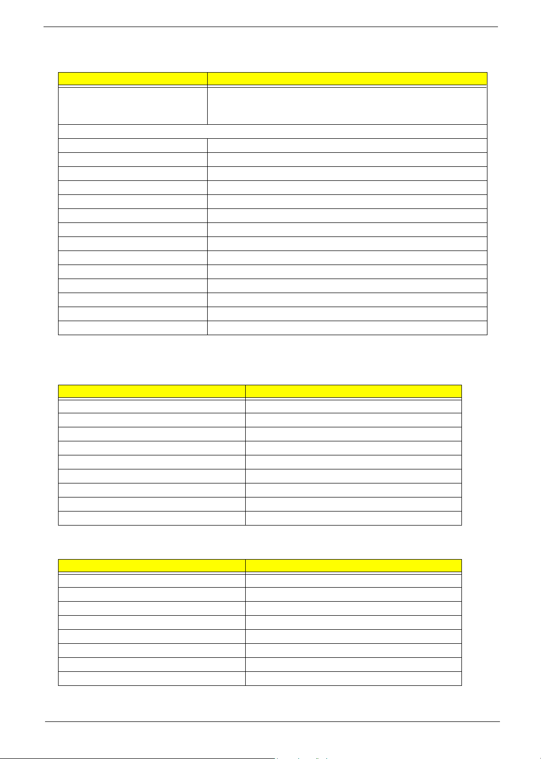
Floppy disk drive Interface
Item Specification
Vendor & Model Name Panasonic JU-256A048P
Mitsumi D353M3D-R694005
NEC FD1231T-STD-R2
Floppy Disk Specifications
Media Recognition 1.44 MB
Cylinders 80
Tracks 160
Rotational speed (RPM) 300
Read/write heads 2
Encoding method MFM/FM
Power requirement (max) 5V
Startup (peak) 290mA
Maximum Seeking (RMS) 710mA
Voltage tolerance (V) +5V +/- 10%
MTBF (Mean Time Between Failure) 30,000
Floppy disk drive controller Embedded in SMSC LPC47M192
Floppy disk drive controller resident bus LPC
Support FDD format 360KB, 720KB, 1.2MB, 1.44MB, 2.88MB; 3-mode
Parallel Port
Item Specification
Parallel port controller Embedded in SMSC LPC47M192
Parallel port controller resident bus LPC
Number of parallel ports 1
Support SPP, ECP, EPP SPP/ ECP / EPP 1.7 & 1.9
Connector type 25-pin D-type female connector
Parallel port function control Enable/disable by BIOS Setup
Optional ECP DMA channel (in BIOS Setup) DMA channel 1 / DMA channel 3
Optional parallel port I/O address (via BIOS Setup) 378-37F / 278-27F / 778-77A
Optional parallel port IRQ (via BIOS Setup) IRQ5 / IRQ7
Serial Port
Item Specification
Serial port controller Embedded in SMSC LPC47M192
Serial port controller resident bus LPC
Number of serial port 2
Serial ports location COM1, COM 2(Reserve for header)
16C550 UART support Yes
Connector type 15-pin connector (1 with pin reserve)
Optional serial port I/O address (via BIOS Setup) 2F8-2FF / 3F8-3FF
Optional serial port IRQ (via BIOS Setup) 4 / 3
20 Chapter 1
Page 30
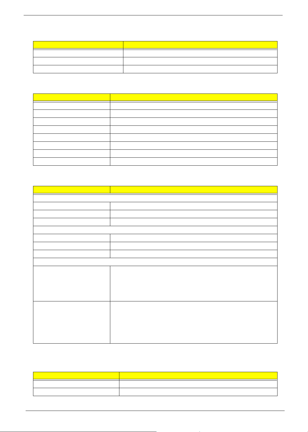
USB Port
Items Specifications
Universal UHCI USB 1.1
Universal EHCI USB 2.0
USB Class Support legacy keyboard for legacy mode
Main Board Major Chips
Item Controller
North Bridge Intel 865G/865GV
South Bridge Intel ICH5R/ICH5
Super I/O controller SMSC LPC 47M192
Audio Codec Realtek ALC202 A
LAN controller Broadcom 5705
HDD controller Built-in Intel® ICH5R/ICH5
Keyboard controller Built-in Intel® ICH5R/ICH5
RTC Built-in Intel® ICH5R/ICH5
Environmental Requirements
Item Specifications
Temperature
Operating +10 to +35°C
Non-operating -10 to +60°C
Non-operating -20 to +60°C (Storage package)
Humidity
Operating 15% to 80% RH, non-condensing
Non-operating 15% to 80% RH, non-condensing (Unpacked)
Non-operating 15% to 80% RH, non-condensing (Storage package)
Vibration
Operating:
Sweep rate:
Direction:
Test cycles:
Non-operating:
(Packed)
Sweep rate:
Direction:
Test cycles:
5~16.2 Hz 0.38mm (peak to peak)
16.2~250 Hz 0.2G
1 octave/minute
X, Y, Z axis
2 cycles per axis
5~27.1 Hz 0.6G
27.1~50 Hz 0.4mm (peak to peak)
50~500 Hz 2.0G
0.5 coactive/minute
X, Y, Z axis
4 cycles per axis
Switching Power Supply
A-1 Input frequency
Normal Frequency Frequency Variation Range
50Hz 47Hz to 53Hz
60Hz 57Hz to 63Hz
Chapter 1 21
Page 31
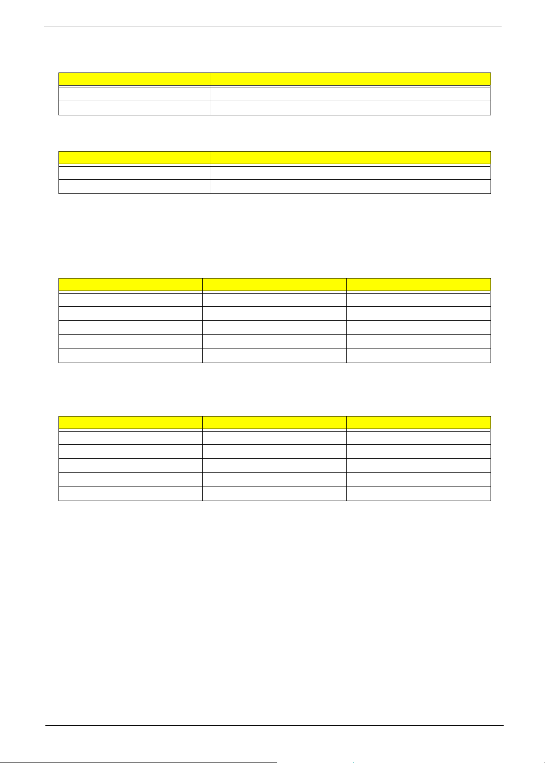
A-2 Input voltage
Nominal Voltage Variation Range
100 - 120 VRMS 90-132 VRMS
200 - 240 VRMS 180-264 VRMS
A-3 Input current
Input Current Measuring Range
6A 90 -132 VRMS
3A 180 - 264 VRMS
(This is 200W power supply)
T This “4A” includes the outlet supply current: 2A
T Measure at line input 90 VRMS and maximum load condition.
200W Power Supply
Output Requirements Regulation Current Rating (Max)
+5V +5% 18A
+12V +5% 14A
-12V +10% 0.5A
+3.3V +5% 14A
+5VSB +5% 2A
NOTE: 1. +5V & +3.3V total power is 110W max.
250W Power Supply
Output Requirements Regulation Current Rating (Max)
+5V +5% 25A
+12V +5% 17A
-12V +10% 0.8A
+3.3V +5% 20A
+5VSB +5% 2A
1. +5V & +3.3V total power is 150W max.
22 Chapter 1
Page 32
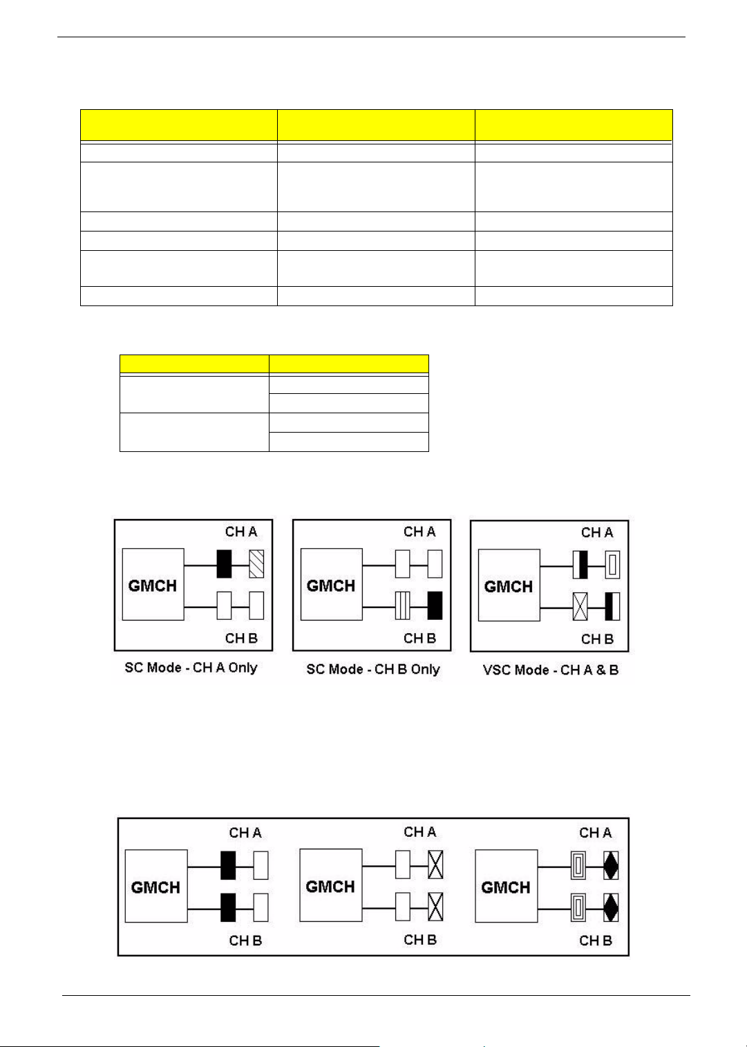
Memory Channel Mode
Single Channel /
Virtual Single Channel
DIMM Population No restrictions Matching DIMM pairs
Rank(Row) Size Size of one side of the DIMM
populated in the channel
(64MB - 512MB)
Number of Ranks(Rows) 8 maximum 4 maximum
Channel Size 64 bits 128 bits
Page Size Size read from DIMM
(4KB, 8KB, 16KB)
Burst Length 4 or 8 4
Memory Channel DIMM Slot Number
Channel A DIMM 1
DIMM 2
Channel B DIMM 3
DIMM 4
2x the size of one side of the DIMM
populated in the channel(A or B)
(128MB - 1GB)
2 x Size read from DIMM
(8KB, 16KB, 32KB)
Dual Channel
Single Channel Mode
Single Channel (SC) mode is also referred to as Virtual Single Channel (VSC) mode.
NOTE: Memory channel speed determined by slowest DIMM populated in system
Dual Channel Mode
Chapter 1 23
Page 33

DIMM 1 DIMM 2 DIMM3 DIMM4 To tal
128MB~1GB 128MB~1GB 256MB~2GB
128MB~1GB 128MB~1GB 256MB~2GB
128MB~1GB 128MB~1GB 128MB~1GB 128MB~1GB 512MB~4GB
The following conditions must be met:
T Matched DIMM configuration in each channel
T Same Density (128MB, 256MB, 512MB, etc.)
T Same DRAM technology (128Mb, 256Mb, or 512Mb)
T Same DRAM bus width (x8 or x16)
T Both either single-sided or dual-sided
T Matched in both Channel A and Channel B memory channels
T Populate symmetrical memory slots (Slot 0 or Slot 1)
The following conditions do not
T Same brand
T Same timing specifications
T Same DDR speed
need to be met:
Symmetrical DIMMs must be identical for optimal performance
T Same DIMM density, e.g. 128MB, 256MB, 512MB, etc.
T Same DRAM Technology, e.g. 128M-bit, 256M-bit, etc.
T Same DRAM bus width, e.g. x8 or x16
T Single Sided or Dual Sided
NOTE: Note: Memory interface speed will be set to lowest speed of memory populated
Memory Characteristics
Optimize performance for single or dual channel is obtained with matched DIMM population
Table below shows DIMMs with same Organization and Density, but are non-matching as bus width,
technology and/or external banks are different
T Mixing these DIMMs will put platform into single channel mode
Same # of
DRAM Banks
External
External
Banks
Banks
1128Mb16Mx8 * 8 pcs128MB16Mx64
1128Mb16Mx8 * 8 pcs128MB16Mx64
1256Mb16Mx16 * 4 pcs128MB16Mx64
1256Mb16Mx16 * 4 pcs128MB16Mx64
2128Mb16Mx8 * 16 pcs256MB32Mx64
2128Mb16Mx8 * 16 pcs256MB32Mx64
1256Mb32Mx8 * 8 pcs256MB32Mx64
1256Mb32Mx8 * 8 pcs256MB32Mx64
Different # of
DRAM Banks
Non-Matched
128MB DIMMs
Non-Matched
256MB DIMMs
Same
Organization
Same
Organization
Same
Density
Same
Density
Different Bus
Width
Same
Bus Width
Different
Technology
TechnologyCompositionDensityOrganization
TechnologyCompositionDensityOrganization
Different
Technology
24 Chapter 1
Page 34
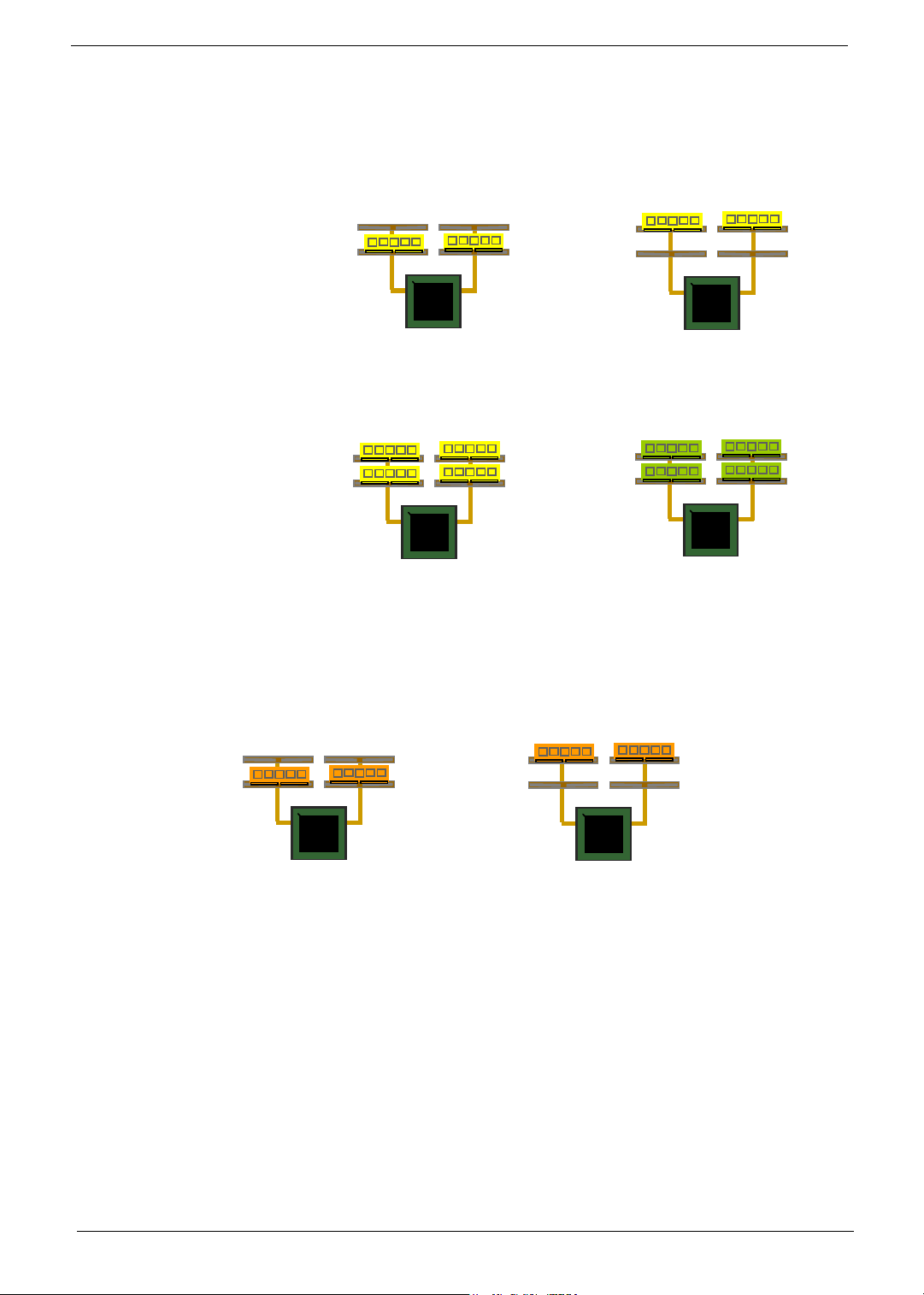
Maximizing Performance
Optimal configurations for highest performance:
T Matched, DDR400, Double-sided DIMMs
T Dual Channel Mode (Symmetrical DIMM population)
Lightly Loaded Config
T Matched, DDR400, Dual Channel Mode
Ch A
Ch A
MCH
MCH
Fully Loaded Config
Ch A
Ch A
MCH
MCH
When not using DDR400, highest performing configuration:
T Symmetrical DIMM population with matched double-sided DIMMs
T Lightly loaded memory population aids in higher performance
T x8 Bus Width and lower DIMM cache latency also assists in higher performance
Ch B
Ch B
Ch B
Ch B
or
or
Ch A
Ch A
Ch A
Ch A
MCH
MCH
MCH
MCH
Ch B
Ch B
Ch B
Ch B
Ch B
Ch A
Ch A
MCH
MCH
Dual Channel memory configuration provides higher performance than Single Channel configurations
Matched DIMMs need to have identical density, DRAM technology, DRAM bus width, and equal number of
memory banks
Optimal platform performance with Dual Channel, DDR400, matched DIMMs
T Fully loaded configurations can be single or double-sided DIMMs
T Lightly loaded configurations need to be double-sided DIMMs
When not using DDR400, best performance obtained with
T Symmetrical DIMM population and matched double-sided DIMMs
T Lightly loaded configuration
Chapter 1 25
Ch B
or
Ch A
Ch A
MCH
MCH
Ch B
Ch B
Page 35

Chapter 2
System Utilities
Most systems are already configured by the manufacturer or the dealer. There is no need to run
Setup when starting the computer unless you get a Run Setup message.
The Setup program loads configuration values into the battery-backed nonvolatile memory called CMOS RAM.
This memory area is not part of the system RAM.
NOTE: If you repeatedly receive Run Setup messages, the battery may be bad. In this case, the system
cannot retain configuration values in CMOS.
Before you run Setup, make sure that you have saved all open files. The system reboots immediately after you
exit Setup.
Chapter 2 26
Page 36
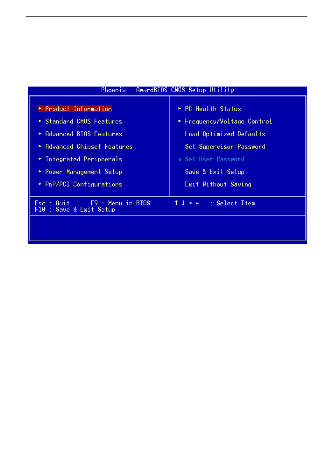
Entering Setup
To enter Setup, press the key c during the POST (Power-on self-test).
NOTE: You must press
The Setup Utility main menu then appears:
c simultaneously while the system is booting.
The above screen is the BIOS Utility Basic Level screen. It allows you to view and change only the basic
configuration of your system.
The command line at the bottom of the menu tells you how to move within a screen and from one screen to
another.
T To select an option, move the highlight bar by pressing w, y, z, or x, then press e.
T To change a parameter setting, press {or }until the desired setting is found, or press
e to pop out the screen with available items for selection.
T Press^ to return to the main menu. If you are already in the main menu, press ^ again to
exit Setup.
The parameters on the screens show default values. These values may not be the same as those in your
system.
The grayed items on the screens have fixed settings and are not user-configurable.
27 Chapter 2
Page 37
Product Information
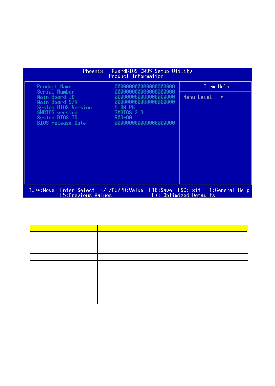
The screen below appears if you select Product Information from the main menu:
The Product Information menu contains general data about the system, such as the product name, serial
number, BIOS version, etc. These information is necessary for troubleshooting (maybe required when asking
for technical support).
The following table describes the parameters found in this menu:
Parameter Description
Product Name Displays the model name of your system.
Serial Number Displays your system’s serial number.
Main Board ID Displays the main board’s identification number.
Main Board S/N Displays your main board’s serial number.
System BIOS Version Specifies the main version of your BIOS utility.
SMBIOS version The System Management Interface (SM) BIOS allows you to check your system
System BIOS ID Displays the system identification number.
BIOS release Date Displays the release date of the BIOS utility.
hardware components without actually opening your system. Hardware checking
is done via software during start up. This parameter specifies the version of the
SMBIOS utility installed in your system.
Chapter 2 28
Page 38
Standard CMOS Features
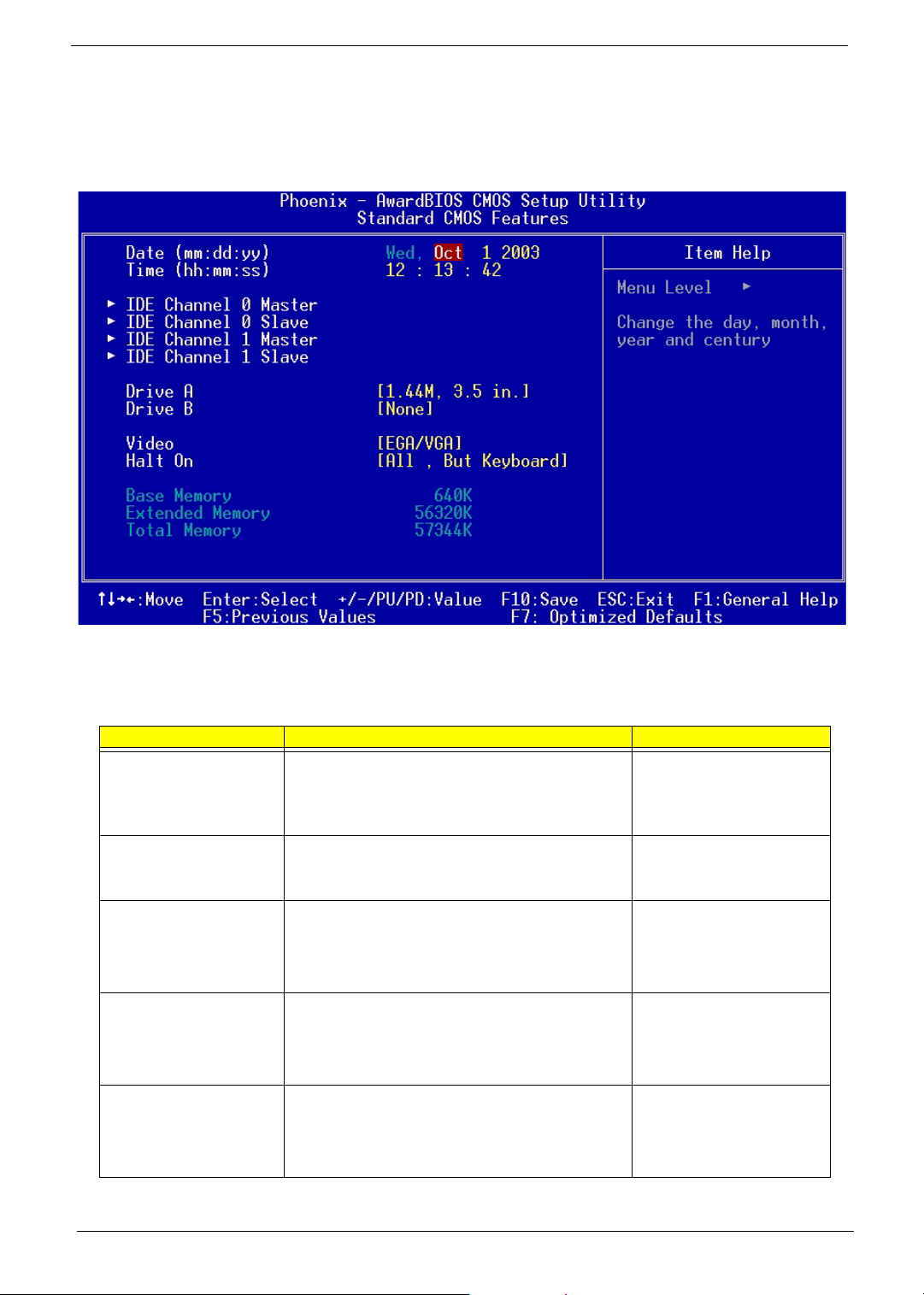
Select “Standard CMOS Features” from the main menu to configure the drives installed in your system.
The following screen shows the Disk Drives menu:
The following table describes the parameters found in this menu.
Parameter Description Options
Date Lets you set the date following the weekday-month-day-
Time Lets you set the time following the hour-minute-second
IDE Channel 0 Master Lets you configure the hard disk drive connected to the
IDE Channel 0 Slave Lets you configure the hard disk drive connected to the
IDE Channel 1 Master Lets you configure the hard disk drive connected to the
year format
format
master port of IDE channel 0.
To enter the IDE Channel 0 Master setup, press
The IDE CD-ROM is always automatically detected.
slave port of IDE channel 0.
To enter the IDE Channel 0 Slave setup, press
The IDE CD-ROM is always automatically detected.
master port of IDE channel 1.
To enter the IDE Channel 1 Master setup, press
The IDE CD-ROM is always automatically detected.
e.
e.
e.
Weekday: Sun, Mon....Sat
Month: Jan, Feb...Dec
Day: 1 to 31
Year: 1980 to 2079
Hour: 0 to 23
Minute: 0 to 59
Second: 0 to 59
(Show the Status:)
None
HDD or CD-ROM Number
(Show the Status:)
None
HDD or CD-ROM Number
(Show the Status:)
None
HDD or CD-ROM Number
29 Chapter 2
Page 39

Parameter Description Options
IDE Channel 1 Slave Lets you configure the hard disk drive connected to the
slave port of IDE channel 1.
To enter the IDE Channel 1 Slave setup, press
The IDE CD-ROM is always automatically detected.
Drive A Allows you to configure your floppy drive A. 1.44 MB, 3.5-inch
Drive B Allows you to configure your floppy drive B. None
Video This item specifies the type of video card in use. The
default setting is VGA/EGA. Since current PCs use
VGA only, this function is almost useless and may be
disregarded in the future.
Halt On This parameter enables you to control the system stops
in case of Power-on self-test (POST) errors.
Base Memory Refers to the portion of memory that is available to
standard DOS programs. DOS systems have an
address space of 1 MB, but the top 384 KB (called high
memory) is reserved for system use. This leaves 640
KB of conventional memory. Everything above 1 MB is
either extended or expanded memory.
Extended Memory Memory above and beyond the standard 1 MB
(megabyte) of base memory that DOS supports.
Extended memory is only available in PCs with an Intel
80286 or later microprocessor. Extended memory is not
configured in any special manner and is therefore
unavailable to most DOS programs. However, MS
Windows and OS/2 can use extended memory.
Total Memory Total base, and extended memory, and I/O ROM 384KB
available to the system.
e.
(Show the Status:)
None
HDD or CD-ROM Number
None
360 KB, 5.25-inch
1.2 MB, 5.25-inch
720 KB, 3.5-inch
2.88 MB, 3.5-inch
360 KB, 5.25-inch
1.2 MB, 5.25-inch
720 KB, 3.5-inch
1.44 MB, 3.5-inch
2.88 MB, 3.5-inch
EGA/VGA
CGA40
CGA80
MONO
All, But Keyboard
All Errors
No Errors
All, But Diskette
All, But Disk/Key
Chapter 2 30
Page 40

IDE Channel 0 Master/Slave and IDE Channel 1 Master/Slave Setup
The following screen appears if you select any of the IDE drive parameters:
The following table describes the parameters found in this menu.
Parameter Description Options
IDE HDD Auto-Detection Auto-detects your hard disk drive. Press Enter
IDE Channel 0 Master/Slave
IDE Channel 1 Master/Slave
Access Mode Selects the HDD access mode Auto
Capacity Shows the size of your hard disk in MB. xxxxx MB
Cylinder Shows your hard disk’s number of cylinders. 0 to 65535
Head Shows your hard disk’s number of heads 0 to 255
Precomp Selects the Precomp number for old HDD parking 0 to 65535
Landing Zone Selects the Landing Zone number for old HDD parking 0 to 65535
Sector Shows your hard disk’s number of sectors 0 to 255
Displays the device type Auto
None
Manual
Large
LBA
CHS
31 Chapter 2
Page 41

Advanced BIOS Features
The following screen shows the Advanced BIOS Features.
The following table describes each Advanced BIOS Features parameter. Settings in boldface are the default
and suggested settings.
Parameter Description Options
Hard Disk Boot Priority Selects the hard disk boot priority. Press [Enter]
Show Hard Disk Name
1/2/3/4/5/6/7/8
Virus Warning Allows you to choose the Virus warning feature for
the IDE hard disk boot sector protection. If this
function is enabled and someone attempts to write
data into this area, BIOS will show a warning
message on screen and alarm beep.
CPU L1 & L2 Cache Uses internal level 1 (L1) and external level 2 (L2)
cache memory to improve performance.
Hyper-Threading Technology The processor uses Hyper-Threading technology to
increase transaction rates and reduces end-user
response times. The technology treats the two
cores inside the processor as two logical
processors that can execute instructions
simultaneously. In this way, the system
performance is highly improved. If you disable the
function, the processor will use only one core to
execute the instructions.
Disabled
Enabled
Enabled
Disabled
Enabled
Disabled
Chapter 2 32
Page 42

Parameter Description Options
Quick Power On Self Test This parameter speeds up POST by skipping some
items that are normally checked.
First Boot Device This parameter allows you to specify the system
boot up search sequence.
Second Boot Device This parameter allows you to specify the system
boot up search sequence.
Third Boot Device This parameter allows you to specify the system
boot up search sequence.
Boot Other Device This parameter allows you to specify the system
boot up search sequence.
Swap Floppy Drive Setting to Enabled will swap floppy drive a: and b:. Enabled
Boot Up Floppy Seek Setting to Enabled will make BIOS seek floppy
drive a: before booting the system.
Boot Up NumLock Status Sets the NumLock status when the system is
powered on. Setting to On will turn on the NumLock
key when the system is powered on. Setting to Off
will allows users to use the arrow keys on the
numeric keypad.
Gate A20 Option This item is to set the Gate A20 status. A20 refers
to the first 64KB of extended memory. When the
default value Fast is selected, the Gate A20 is
controlled by port 92 or chipset specific method
resulting in faster system performance. When
Normal is selected, A20 is controlled by a keyboard
controller or chipset hardware.
Typematic Rate Setting This item is used to enable or disable the typematic
rate setting including Typematic Rate and
Typematic Delay.
Typematic Rate After Typematic Rate Setting is enabled, this item
allows you to set the rate (characters/second) at
which at keys are accelerated.
Typematic Delay This item allows you to select the delay between
when the key was first pressed and when the
acceleration begins
Security Option Specifies the type of BIOS password protection that
is implemented.
Setup means that the password prompt appears
only when end users try to run Setup.
System means that a password prompt appears
every time when the computer is powered on or
when end users try to run Setup.
APIC Mode This field is used to enable or disable the APIC
(Advanced Programmable Interrupt Controller).
Due to compliance with PC2001 design guide, the
system is able to run in APIC mode. Enabling APIC
mode will expand available IRQ resources from the
system.
Enabled
Disabled
Floppy, LS120, Hard Disk,
CD-ROM, ZIP100, LAN (on
board LAN-- Boot from LAN),
Disabled
Floppy, LS120, Hard Disk,
CD-ROM, ZIP100, LAN (on
board LAN-- Boot from LAN),
Disabled
Floppy, LS120, Hard Disk, CD-
ROM, ZIP100, LAN (on board
LAN-- Boot from LAN),
Disabled
Enabled
Disabled
Disabled
Enabled
Disabled
On
Off
Fast
Normal
Enabled
Disabled
Settings: 6,8,10,12,15,20,24
and 30.
Settings: 250, 500, 750 and
1000.
Setup
System
Enabled
Disabled
33 Chapter 2
Page 43
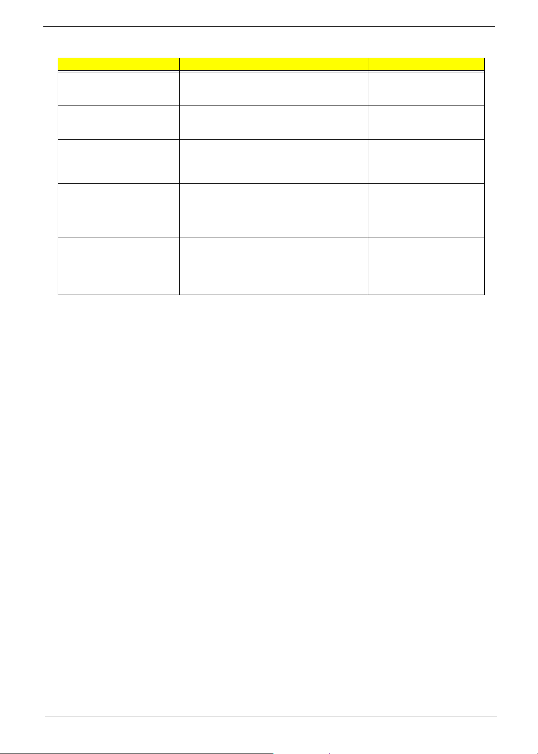
Parameter Description Options
MPS Version Control For OS This field allows you to select which MPS (Multi-
Processor Specification) version to be used for the
operating system.
OS Select For DRAM > 64MB This item is only required if you have installed more
than 64MB of memory and you are running the OS/
2 operating system.
HDD S.M.A.R.T. Capability The S.M.A.R.T (Self-Monitoring, Analysis, and
Reporting Technology) system is a diagnostics
technology that monitors and predicts device
performance.
Report No FDD for WIN 95 For compatibility with Windows 95 logo certification,
select Yes to release IRQ6 when the system
contains no floppy drive. When this setting is set to
Yes, users have to select Disabled for the Onboard
FDC Controller in the Integrated Peripherals menu.
Full Screen LOGO Show This item enables you to show the company logo on
the bootup screen.
Enabled: Shows a still image (logo) on the full
screen at boot.
Disabled: Shows the POST messages at boot.
1.4
1.1
Non-OS2
OS2
Enabled
Disabled
No
Yes
Enabled
Disabled
Chapter 2 34
Page 44

Advanced Chipset Features
The following screen shows the Advanced Chipset Features.
The following table describes each Advanced Chipset Features parameter. Settings in boldface are the default
and suggested settings.
Parameter Description Options
DRAM Timing Selectable Selects whether DRAM timing is controlled by the
SPD (Serial Presence Detect) EEPROM on the
DRAM module. Setting to By SPD enables DRAM
timings to be determined by BIOS based on the
configurations on the SPD. Selecting Manual allows
users to configure the DRAM timings manually.
CAS Latency Time This controls the timing delay (in clock cycles)
before SDRAM starts a read command after
receiving it. Settings: 2, 2.5, 3 (clocks). 2 (clocks)
increases the system performance the most while 3
(clocks) provides the most stable performance.
Active to Precharge Delay The field specifies the idle cycles before
precharging an idle bank.
DRAM RAS# to CAS# Delay This field allows you to set the number of cycles for
a timing delay between the CAS and RAS strobe
signals, used when DRAM is written to, read from
or refreshed. Fast speed offers faster performance
while slow speed offers more stable performance.
By SPD
Manual
2T, 2.5T, 3T
5T, 6T, 7T, 8T
2T, 3T, 4T
35 Chapter 2
Page 45

Parameter Description Options
DRAM RAS# Precharge This item controls the number of cycles for Row
Address Strobe (RAS) to be allowed to precharge.
If insufficient time is allowed for the RAS to
accumulate its charge before DRAM refresh,
refresh may be incomplete and DRAM may fail to
retain data. This item applies only when
synchronous DRAM is installed in the system.
System BIOS Cacheable Selecting Enabled allows caching of the system
BIOS ROM at F0000h-FFFFFh, resulting in better
system performance. However, if any program
writes to this memory area, a system error may
result.
Video BIOS Cacheable Selecting Enabled allows caching of the video BIOS
ROM at C0000h to C7FFFh, resulting in better
video performance. However, if any program writes
to this memory area, a system error may result.
Memory Hole at 15M-16M In order to improve performance, certain space in
memory can be reserved for ISA peripherals. This
memory must be mapped into the memory space
below 16MB. When this area is reserved, it cannot
be cached.
Delay Prior to Thermal When the CPU temperature reaches a factory
preset level, a thermal monitoring mechanism will
be enabled following the appropriate timing delay
specified in this field. With the thermal monitoring
enabled, clock modulation controlled by the
processor’s internal thermal sensor is also
activated to keep the processor within allowable
temperature limit.
AGP Aperture Size (MB) This setting controls just how much system RAM
can be allocated to AGP for video purposes. The
aperture is a portion of the PCI memory address
range dedicated to graphics memory address
space. Host cycles that hit the aperture range are
forwarded to the AGP without any translation.
Init Display First This item specifies which VGA card is your primary
graphics adapter.
On-Chip VGA This setting determines whether the system RAM
can be allocated to on-chip video controller for
video purposes. When setting to Enabled, up to
128MB system RAM will be allocated to on-chip
video controller.
On-Chip Frame Buffer Size Frame Buffer is the video memory that stores data
for video display (frame). This field is used to
determine the memory size for Frame Buffer.
Larger frame buffer size increases video
performance.
Boot Display Use this field to select the type of device you want
to use as the display(s) of the system.
2T, 3T, 4T
Enabled
Disabled
Disabled
Enabled
Disabled
Enabled
4 Min, 8Min, 16 Min, 32 Min
4, 8, 16, 32, 64, 128 and 256
PCI Slot
Onboard/AGP
Enabled
Disabled
1M, 8M, 16M
Auto, CRT, TV, EFP
Chapter 2 36
Page 46
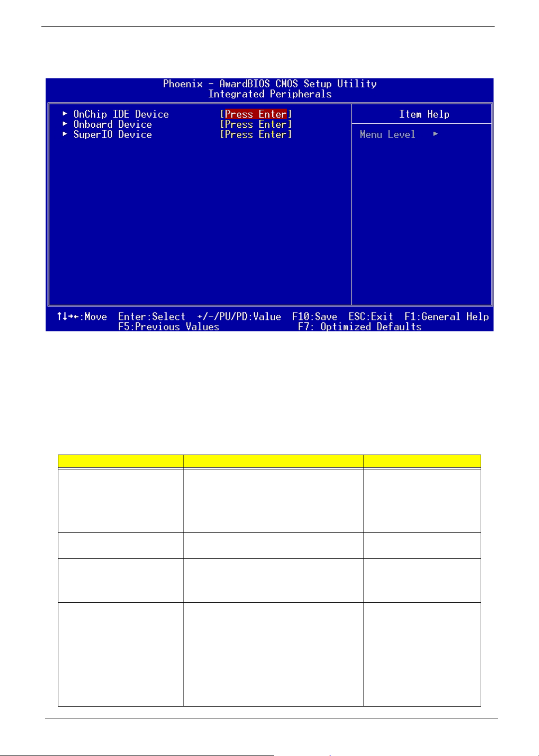
Integrated Peripherals
The following table describes each Integrated Peripherals parameter. Settings in boldface are the default and
suggested settings.
OnChip IDE Device
Press [Enter] to enter the sub-menu and the following screen appears:
Parameter Description Options
IDE HDD Block Mode Block mode is also called block transfer, multiple
commands, or multiple sector read/write. If your
IDE hard drive supports block mode (most new
drives do), select [Enabled] for automatic
detection of the optimal number of block read/
write per sector the drive can support.
IDE DMA Transfer Access This item allows you to enabled the transfer
access of the IDE DMA.
On-Chip Primary PCI IDE
On-Chip Secondary PCI IDE
IDE Primary Master PIO
IDE Primary Slave PIO
IDE Secondary Master PIO
IDE Secondary Slave PIO
The integrated peripherals controller contains an
IDE interface with support for two IDE channels.
Choose Enabled to activate each channel
separately.
The four IDE PIO (Programmed Input/Output)
fields let you set a PIO mode (0-4) for each of the
four IDE devices that the onboard IDE interface
supports. Modes 0 through 4 provide
successively increased performance. For
example, mode 0 data transfer rate is 3.3MB/s,
mode 1 is 5.2 MB/s, mode 2 is 8.3MB/s, mode 3
is 11.1 MB/s and mode 4 is 16.6MB/s. In Auto
mode, the system automatically determines the
best mode for each device.
Enabled
Disabled
Enabled
Disabled
Enabled
Disabled
Auto, mode 1, mode 2, mode 3
and mode 4
37 Chapter 2
Page 47

Parameter Description Options
IDE Primary Master UltraDMA
IDE Primary Salve UltraDMA
IDE Secondary Master UltraDMA
Secondary Slave UltraDMA
SATA Mode Select SATA Mode IDE, RAID
On-Chip Serial ATA This setting is used to specify the SATA
Serial ATA Port 0/1 Mode Select a compatible mode for Port 1 and Port 2
Ultra DMA/33 implementation is possible only if
your IDE hard drive supports it and the operating
environment includes a DMA driver. If your hard
drive and your system software both support
Ultra DMA/33, Ultra DMA/66 and Ultra DMA/100
select Auto to enable BIOS support.
controller.
If [Legacy Mode] is selected, PATA and SATA
will be combined.
If [Native Mode] is selected, PATA and SATA will
both be enabled.
If [Auto] is selected, PATA and SATA will be
arranged by BIOS, and you will be able to see
the IDE Device status listed in Standard COMS
Features.
from Award setting to the chipset settings:
Primary Master: Compatible Mode with Serial
ATA Port 1 set to Primary Master.
Primary Slave: Compatible Mode with Serial
ATA Port 1 set to Primary Slave.
Secondary Master: Compatible Mode with
Serial ATA Port 1 set to Secondary Master.
Secondary Slave: Compatible Mode with Serial
ATA Port 1 set to Secondary Slave.
Primary Master: Compatible Mode with only
Serial ATA Enabled and Port 1 set to Primary
Master.
Secondary Master: Compatible Mode with only
Serial ATA Enabled and Port 1 set to Secondary
Master.
SATA0 Master: Enhance Mode with Port 1 set to
Native Mode Master.
SATA1 Master: Enhance Mode with Port 2 set to
Native Mode Master.
Auto
Disables
Disable, Auto, Legacy Mode,
Native Mode
Primary Master
Primary Slave
Secondary Master
Secondary Slave
Primary Master
Secondary Master
SATA0 Master
SATA1 Master
Onboard Device
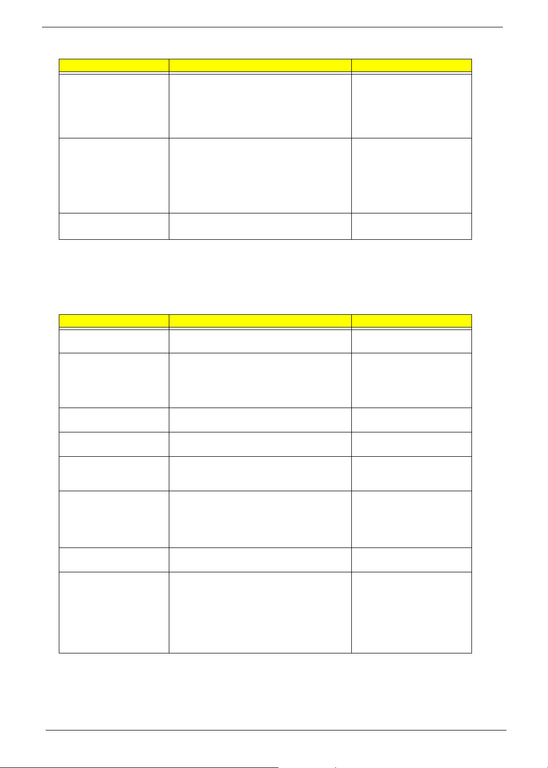
Press [Enter] to enter the sub-menu and the following screen appears:
Parameter Description Options
USB Controller This setting is used to enable/disable the
onboard USB controller.
USB 2.0 Controller Set to Enabled if you need to use any USB 2.0
device in the operating system that does not
support or have any USB 2.0 driver installed,
such as DOS.
USB Keyboard Support This item allows the BIOS to interact with a USB
keyboard or mouse to work with MS-DOS based
utilities and non-Windows modes.
Chapter 2 38
Enabled
Disabled
Enabled
Disabled
Enabled
Disabled
Page 48
Parameter Description Options
USB Mouse Support This item lets you enable or disable the USB
mouse driver within the onboard BIOS. The
keyboard driver simulates legacy mouse
command and lets you use a USB mouse during
POST or after boot if you do not have a USB
driver in the operating system.
AC97 Audio Auto allows the motherboard’s BIOS to detect
whether you’re using any audio device. If so, the
onboard audio controller will be enabled. If not,
the onboard audio controller will be disabled. If
you want to use different controller cards to
connect audio connectors, set the field to
Disabled.
Onboard LAN Control This setting controls the onboard LAN controller. Enabled
Enabled
Disabled
Enabled
Disabled
Disabled
SuperIO Device
Press [Enter] to enter the sub-menu and the following screen appears:
Parameter Description Options
POWER ON Function This controls how the PS/2 mouse or keyboard
can power on the system.
Onboard FDC Controller Select Enabled if your system has a floppy disk
controller (FDD) installed on the system board
and you wish to use it. If you install add-on FDC
or the system has no floppy drive, select
Disabled in this field.
Onboard Serial Port 1 This option is used to assign the I/O address and
interrupt request (IRQ) for onboard serial port 2
Onboard Serial Port 2 This option is used to assign the I/O address and
interrupt request (IRQ) for onboard serial port 2
Onboard Parallel Port This option is used to assign the I/O address and
interrupt request (IRQ) for the onboard parallel
port.
Parallel Port Mode Enables you to set the data transfer protocol for
your parallel port.
SPP (Standard Parallel Port), EPP (Enhanced
Parallel Port), ECP (Extended Capabilities Port)
and ECP+EPP.
ECP Mode Use DMA When the onboard parallel port is set to ECP
mode, the parallel port can use DMA 3 or DMA 1.
PWRON After PWR-fail This item specifies whether your system will
reboot after a power failure or interrupt occurs.
Available settings are:
Off: Leaves the computer in the power off state.
On: Leaves the computer in the power on state.
Former-sts: Restores the system to the status
before power failure or interrupt occurred.
BUTTON ONLY, Any KEY,
Hotkey F11
Enabled
Disabled
Disable, 3F8/IRQ4, 2F8/IRQ3,
3E8/IRQ4, 2E8/IRQ3, Auto
Disable, 3F8/IRQ4, 2F8/IRQ3,
3E8/IRQ4, 2E8/IRQ3, Auto
Disabled, 378/IRQ7, 278/IRQ5,
3BC/IRQ7
SPP, EPP1.9+SPP, ECP,
EPP1.9+ECP, PRINTER,
EPP1.7+SPP, EPP1.7+ECP
3, 1
Off, On, Former-sts
39 Chapter 2
Page 49
Power Management Setup
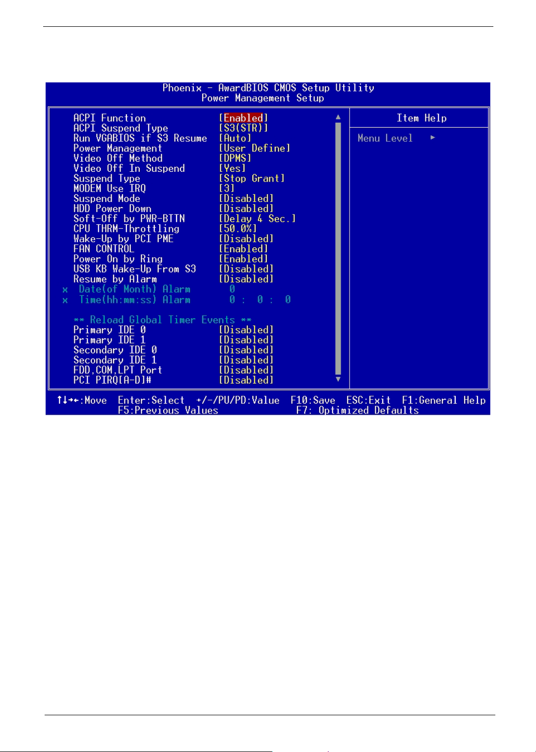
The Power Management menu lets you configure the system power-management feature. It works only in
APM mode.
IMPORTANT:If an ACPI-aware operating system such as Windows 98 or Windows 2000 is installed in ACPI
mode, the operating system will use the ACPI interfaces. Then the settings in Power
Management page is non-effective.
The following screen shows the Power Management parameters and their default settings:
Chapter 2 40
Page 50

The following table describes the parameters found in this menu.
Parameter Description Options
ACPI Function Enabled/Disable ACPI Function. Enabled
Disabled
ACPI Suspend Type This item specifies the power saving modes for
ACPI function. Options are:
S1/POS: The S1 sleep mode is a low power
state. In this state, no system context is lost
(CPU or chipset) and hardware maintains all
system context.
S3/STR: The S3 sleep mode is a lower power
state where the information of system
configuration and open applications/files is
saved to main memory that remains powered
while most other hardware components turn off
to save energy. The information stored in
memory will be used to restore the system
when a “wake up” event occurs.
Run VGABIOS if S3 Resume When ACPI Suspend Mode is set to S3 or
S1&S3, users can select the options in this
field. Selecting [Yes] allows BIOS to call
VGABIOS to initialize the VGA card when
system wakes up (resumes) from S3 sleep
state. The system resume time is shortened
when you disable the function, but system will
need an AGP driver to initialize the VGA card.
Therefore, if the AGP driver of the card does
not support the initialization feature, the display
may work abnormally or not function after
resuming form S3.
Power Management This item is used to select the degree (or type)
of power saving and is related to these modes:
Suspend Mode and HDD Power Down.
Min Saving: Minimum Power Management.
Suspend Mode=1 Hour
Max Saving: Maximum Power Management.
Suspend Mode=1 Min
User Define: Allows end users to configure
each mode separately.
Video Off Method This determines the manner in which the
monitor is blanked.
V/H SYNC+Blank: This selection will cause
the system to turn off the vertical and
horizontal synchronization ports and write
blanks to the video buffer.
Blank Screen: This option only writes blanks
to the video buffer.
DPMS: Initial display power management
signaling.
Video Off In Suspend This option enables the monitor to be turned off
during the suspend mode.
Suspend Type This item allows you to select he suspend type
for system power management.
MODEM Use IRQ This determines the IRQ in which the MODEM
can use. Activity of the selected IRQ always
awakens the system.
S1/POS
S3/STR
Auto, Yes, No
User Define
Min Saving
Max Saving
DPMS
V/H SYNC+Blank
Blank Screen
Yes
No
Stop Grant
PwrOn Suspend
3, 4, 5, 7, 9, 10, 11, NA
41 Chapter 2
Page 51

Parameter Description Options
Suspend Mode If system activity is not detected for the length
of time specified in this field, all devices except
CPU will be shut off.
HDD Power Down If HDD activity is not detected for the length of
time specified in this field, the hard disk drive
will be powered down while all other devices
remain active.
Soft-Off by PWR-BTTN This is a specification of ACPI and supported
by hardware. When Delay 4 sec. is selected,
the soft power switch on the front panel can be
used to control power On, Suspend and Off. If
the switch is pressed less than 4 sec. during
power On, the system will go into Suspend
mode. If the switch is pressed longer than 4
sec, the system will be turned Off. The other
setting is Instant-Off, where the soft power
switch is only used to control On and Off, there
is no need to press 4 sec, and there is no
Suspend.
CPU THRM-Throttling
Wake-Up by PCI PME These fields specify whether the system will be
FAN CONTROL This setting is used to enable/disable the fan
Power-On by Ring When Enabled, any fax/ modem activity wakes
USB KB Wake-up from S3 This setting allows you to enter “Any Key”
Resume by Alarm
Primary IDE 0/1
Secondary IDE 0/1
FDD, COM, LPT Port
PCI PIRQ[A-D] #
The item allows you to specify the CPU speed
(at percentage) to which it will slow down when
the CPU reaches the predetermined overheat
temperature.
awakened from power saving modes when
activity or input signal of the specified
hardware peripheral or component is detected.
speed control function.
up the system from suspend mode.
(max. 8 numbers) to wake up the system from
S3 state.
Use this option to set the date and time for your
computer to boot up.
Date (of month) Alarm
system will boot up. Set it to 0 if you want to
boot everyday.
Time (hh:mm:ss) Alarm
minute and second when system will boot up.
The global timer is the hardware timer that
counts down to the power saving modes. If the
monitoring of the listed hardware peripherals or
components is enabled, the activity of the specified peripherals or components will awaken the
system or reload the original count of global
timer when they are accessed.
* - Indicate month when
* - Indicate the hour,
NOTE: In ACPI mode: Valid-S5 and S4. In APM mode: Valid- shutdown
Disabled, 1 Min, 2 Min, 4 Min, 8
Min, 12 Min, 20 Min, 30 Min, 40
Min, 1 Hour
Disabled
1 Min through15 Min
Delay 4 sec.
Instant-Off
From 12.5% to 87.5% at 12.5%
increment
Disabled
Enabled
Enabled
Disabled
Enabled
Disabled
Disabled
Enabled
Disabled
Enabled
* Set Resume by Alarm to
Enabled, then press
show the range of Date and Time
Alarm.
Disabled
Enabled
e to
Chapter 2 42
Page 52
PnP/PCI Configurations
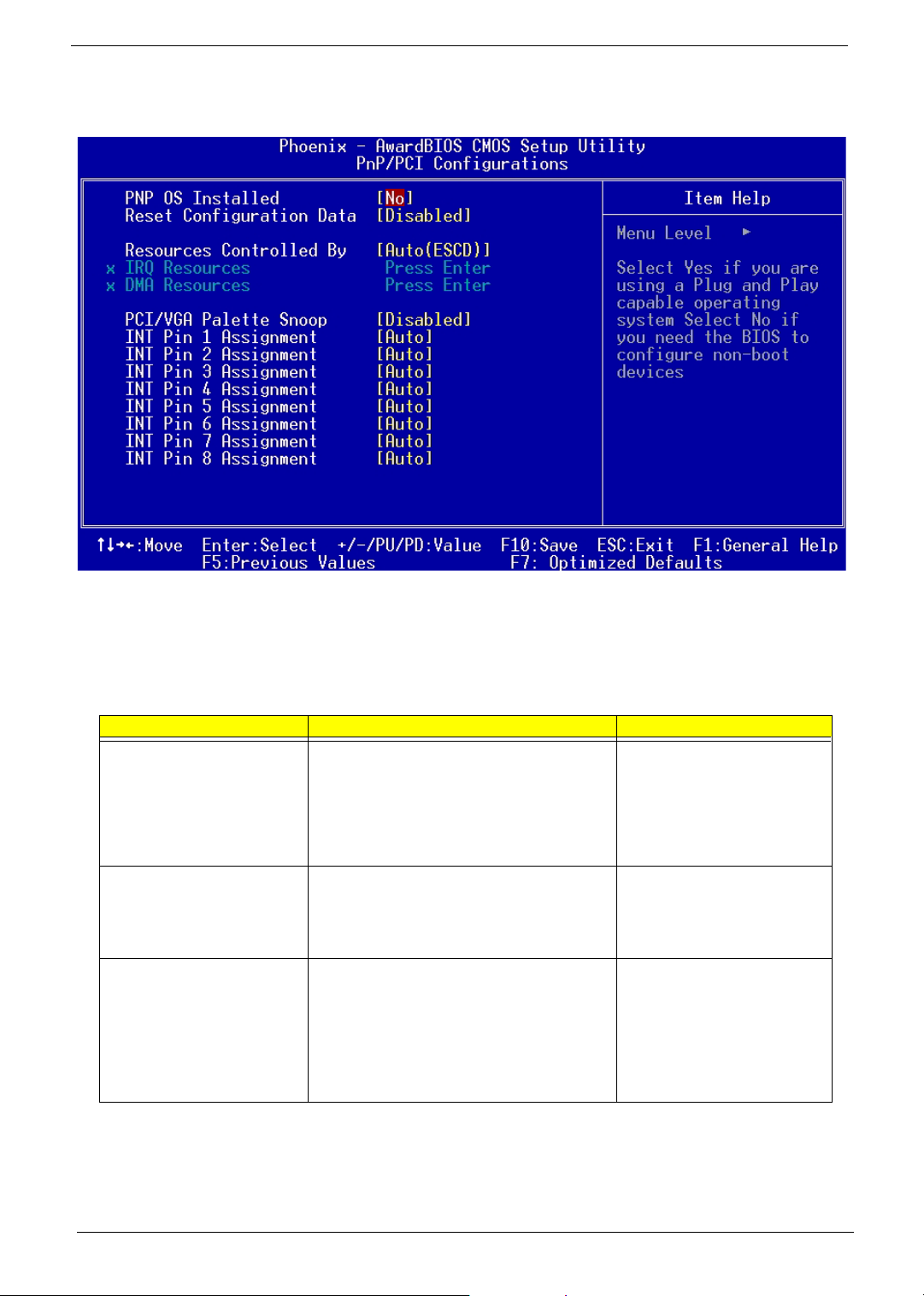
The table below describes each PnP/PCI configuration parameter. Settings in boldface are the default and
suggested settings.
Parameter Description Options
PNP OS Installed When set to [Yes], BIOS will only initialize the
PnP cards used for booting (VGA, IDE, SCSI).
The rest of the cards will be initialized by the PnP
operating system like Windows 98. When set to
[No], BIOS will initialize all the PnP cards. So,
select [Yes] if your operating system is Plug &
Play aware.
Reset Configuration Data Select Enabled to reset Extended System
Configuration Data (ESCD) when you exit Setup
if you have installed a new add-on and the
system configuration has caused such a serious
conflict that the OS cannot boot.
Resources Controlled By The Award Plug and Play BIOS has the capacity
to automatically configure all of the boot and Plug
and Play compatible devices. However, this
capability means absolutely nothing unless you
are using a Plug and Play operating system such
as Windows 95/98. If you set this field to
“manual” choose specific resources by going into
each of the sub menu that follows this field.
No
Yes
Disabled
Enabled
Auto (ESCD)
Manual
43 Chapter 2
Page 53

Parameter Description Options
IRQ Resources
DMA Resources
PCI/VGA Palette Snoop When set to Enabled, multiple VGA devices
The items are adjustable only when Resources
Controlled By is set to Manual. Press <Enter>
and you will enter the sub-menu of the items.
Legacy ISA for devices compliant with the
original PC AT bus specification, PCI/ISA PnP for
devices compliant with the Plug and Play
standard whether designed for PCI or ISA bus
architecture.
operating on different buses can handle data
from the CPU on each set of palette registers on
every video device. Bit 5 of the command
register in the PCI device configuration space is
the VGA Palette Snoop bit (0 is disabled). For
example, if there are two VGA devices in the
computer (one PCI and one ISA) and the:
Disabled: Data read or written by the CPU is
only directed to the PCI VGA device’s palette
registers.
Enabled: Data read or written by the CPU is
directed to both the PCI VGA device’s palette
registers and the ISA VGA device’s palette
registers, permitting the palette registers of both
VGA devices to be identical.
NOTE: Some VGA cards have required settings
for this feature. Check your VGA card
manual before setting this parameter.
INT Pin 1~8 Assignment The items allow you to assign an IRQ line to INT
Pin #1~8 separately. Selecting Auto allows BIOS
to determine the appropriate IRQ for each INT
pin.
Disabled
Enabled
Auto, 3, 4, 5, 7, 9, 10, 11, 12, 14,
15
Chapter 2 44
Page 54
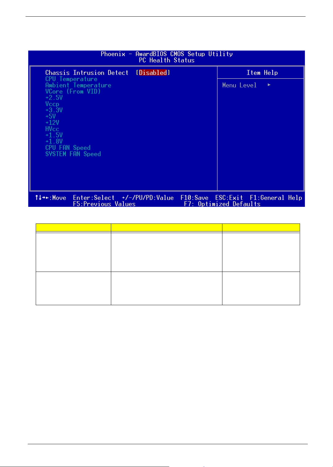
PC Health Status
Parameter Description Options
Chassis Intrusion Detect The field enables or disables the feature of
recording the chassis intrusion status and issuing
a warning message if the chassis is once
opened. To clear the warning message, set the
field to Reset. The setting of the field will
automatically return to Enabled later.
CPU Temperature, Ambient
Temperature, VCore (From VID),
+2.5V Vccp, +3.3V, +5V, +12V,
HVcc, +1.5V, +1.8V, CPU FAN
Speed, System FAN Speed
These items display the current status of all of
the monitored hardware devices/components
such as CPU voltages, temperatures and all
fans’ speeds.
Disabled
Enabled
45 Chapter 2
Page 55

Frequency Control
The following table describes the parameters found in this menu.
Parameter Description Option
CPU Clock Ratio Core Clock Frequency to System Bus Ratio (RO)
Auto Detect PCI CLK This option allows you to enable/disable the feature of auto
detecting the clock frequency of the installed PCI bus.
Enabled
Disabled
Chapter 2 46
Page 56
Load Optimized Settings
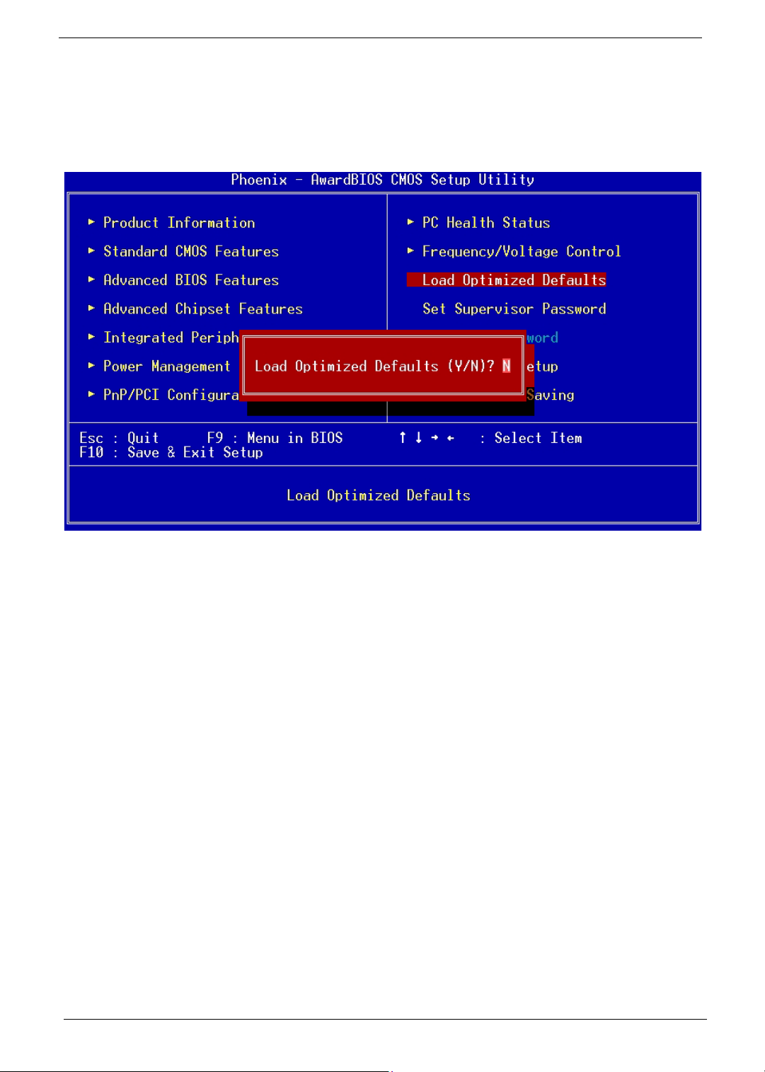
You need to reload the BIOS default settings every time you make changes to your system hardware
configuration (such as memory size, CPU type, hard disk type, etc.); otherwise, BIOS will keep the previous
CMOS settings. Selecting this option displays the following dialog box:
Choosing Yes enables BIOS to automatically detect the hardware changes that you have made in your
system. This option also allows you to restore the default settings.
Choosing No returns you to the main menu without loading the default settings.
47 Chapter 2
Page 57
System Security
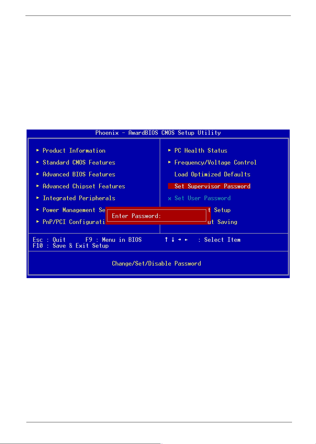
The Setup program has a number of security features to prevent unauthorized access to the system and its
data.
Set Supervisor Password
To set a password:
1. At the prompt, type your password. Your password can be up to 8 alphanumeric characters. When you
type the characters, they appear as asterisks on the password screen box.
2. After typing the password, press e.
3. At the next prompt, re-type your password and press e again to confirm the new password. After the
password entry, the screen automatically reverts to the main screen.
To disable the password, press
confirming that the password has been disabled.
Chapter 2 48
e when prompted to enter the password. The screen displays a message
Page 58
Set User Password
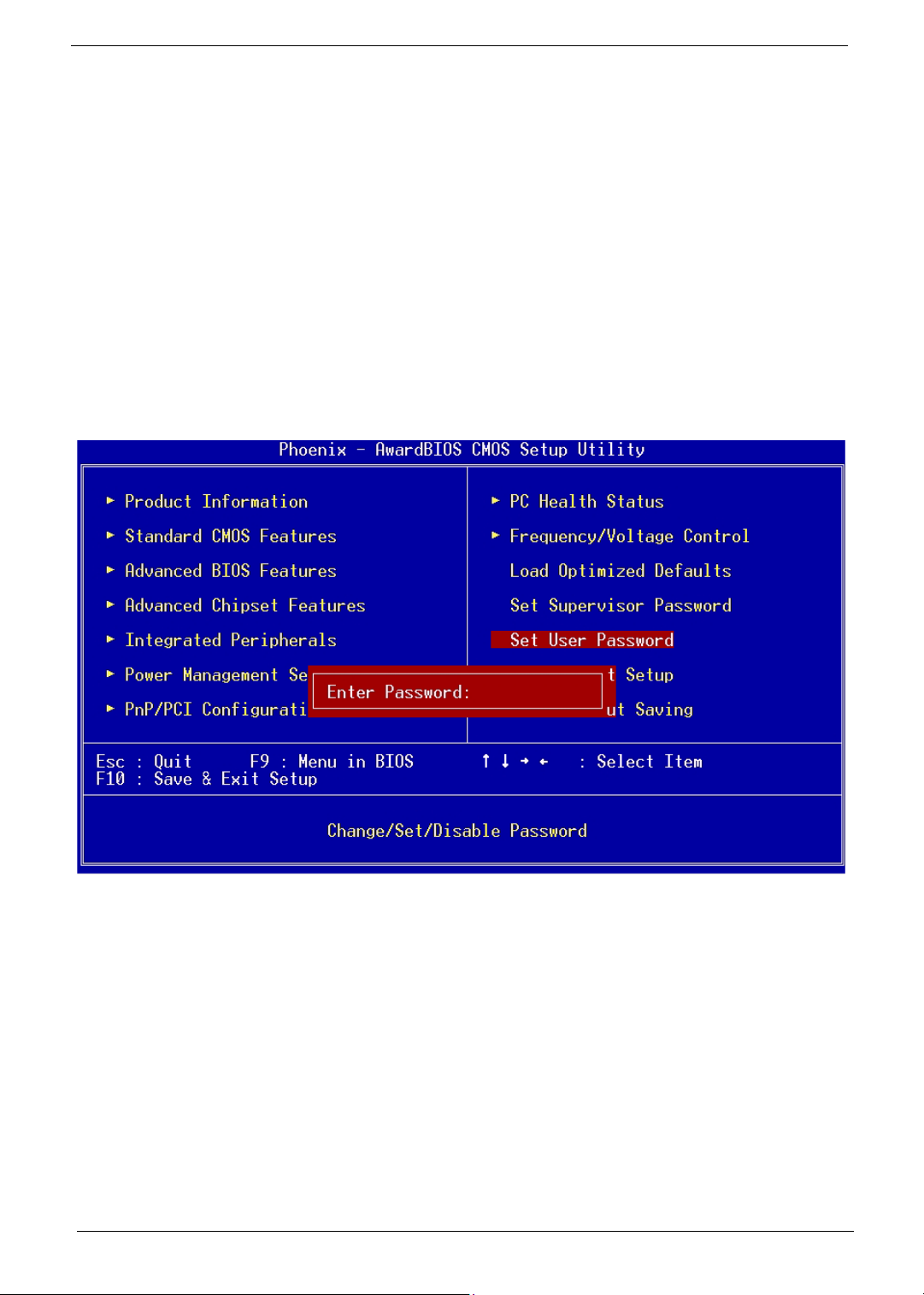
IMPORTANT:To show the “Set User Password”:
1. Choose “Set Supervisor Password” and press
2. Type the password and then press e.
3. Confirm the password, and then press e.
4. The screen as below with “Set User Password” enabled will be shown.
To set a password:
1. At the prompt, type your password. Your password can be up to 8 alphanumeric characters. When you
type the characters, they appear as asterisks on the password screen box.
2. After typing the password, press
3. At the next prompt, re-type your password and press e again to confirm the new password. After the
password entry, the screen automatically reverts to the main screen.
e.
e.
To disable the password, press
confirming that the password has been disabled.
e when prompted to enter the password. The screen displays a message
Bypassing the Password
If you forgot your password, you can bypass the password security feature through hardware configuration.
RTC Battery
Follow these steps to bypass the password:
1. Turn off and unplug the system.
2. Open the system housing. Take off battery and short it.
3. Place on RTC battery, reboot the system and enter setup menu, to load default setting.
49 Chapter 2
Page 59

Clear CMOS
Follow these steps to bypass the password:
1. Reset CMOS, by adjusting JBAT1 to 2-3
2. Reboot the system.
3. Adjust the JP2 back to 1-2
NOTE:
JBAT1: Clear CMOS
1-2 Normal
2-3 Clear CMOS
Please refer to the following
JP2 CMOS Check
Chapter 2 50
Page 60

Save & Exit Setup
Highlight this item and press <Enter> to save the changes that you have made in the Setup Utility and exit the
Setup Utility.
When the Save and Exit dialog box appears, press <Y> to save and exit, or press <N> to return to the main
menu.
51 Chapter 2
Page 61
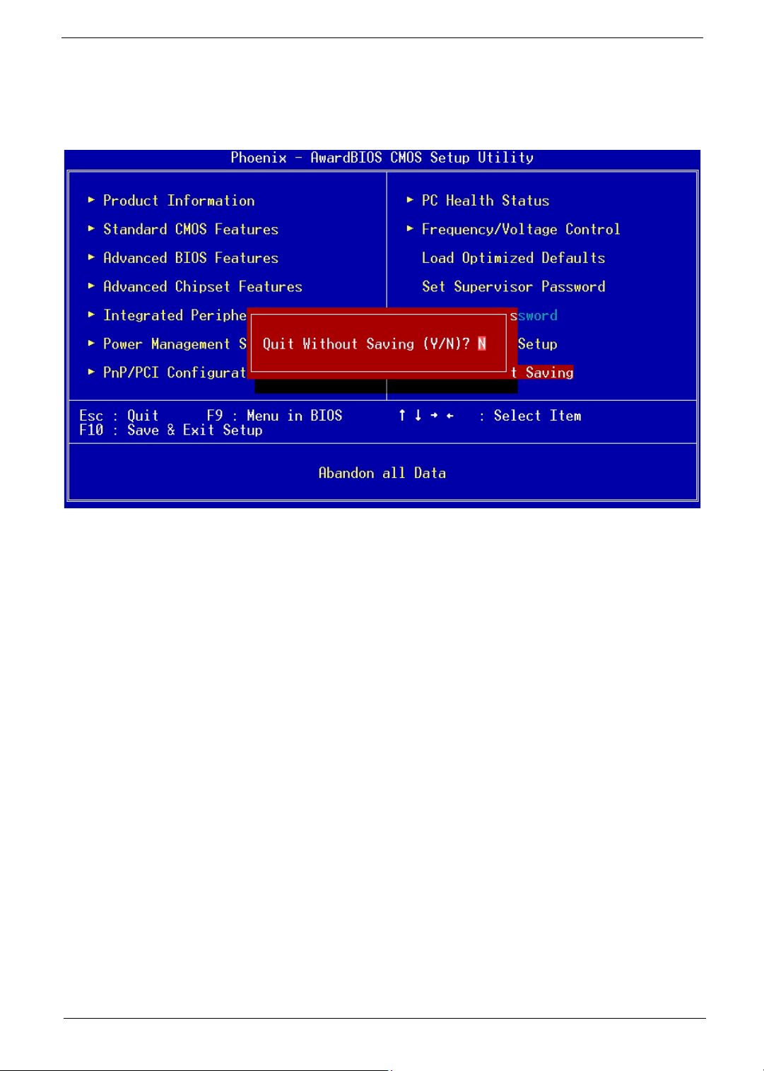
Exit Without Saving
Highlight this item and press <Enter> to discard any changes that you have made in the Setup Utility and exit
the Setup Utility.
When the Exit Without Saving dialog box appears, press <Y> to discard changes and exit, or press <N> to
return to the main menu.
NOTE: If you have made settings that you do not want to save, use the "Exit Without Saving" item and press
<Y> to discard any changes you have made.
Chapter 2 52
Page 62

Intel Serial ATA RAID Introduction
The southbridge ICH5R provides a hybrid solution that combines two independent SATA ports for support of
up to two Serial ATA (Serial ATA RAID) drives. Serial ATA (SATA) is the latest generation of the ATA interface.
SATA hard drives deliver blistering transfer speeds of up to 150MB/sec. Serial ATA uses long, thin cables,
making it easier to connect your drive and improving the airflow inside your PC.
1. Supports 150 MB/s transfers with CRC error checking
2. Data handling optimizations including tagged command queuing, elevator seek and packet chain
command.
Following are the Parallel ATA (P-ATA) and Serial ATA (S-ATA) device configurations supported by Intel
ICH5R.
Introduction
Following are the Parallel ATA (P-ATA) and Serial ATA (S-ATA) device configurations supported by Intel
ICH5R.
ATA Operate Mode
There are two modes to select: Legacy mode and Native mode.
Legacy Mode:
T In this mode, system BIOS just assign the traditional 14 and 15 IRQs to use for HDD.
T Older OSs that do not support switch to Native Mode (DOS, Win2K, Win98/ME...) should set SATA
and PATA to Legacy Mode.
T Maximum 4 ATA devices to connect.
T Combine mode and Non-Combine mode.
(1) Non-Combined Mode: P-ATA devices only. Maximum of 4 devices.
(2) Non-Combined Mode: S-ATA devices only. Maximum of 2 devices.
53 Chapter 2
Page 63
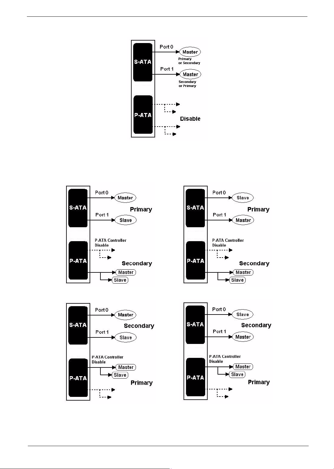
(3) Combined Mode: S-ATA devices and P-ATA devices. Maximum of 2 devices each, thus total
4 devices at maximum.
Chapter 2 54
Page 64
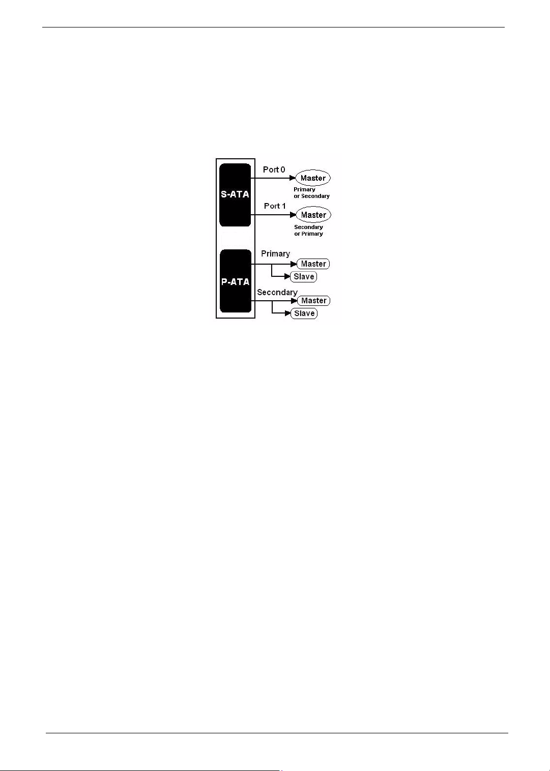
Native Mode:
T In this mode, system BIOS will search all available IRQs to use for HDD.
T New OS that support switch to Native Mode (WinXP, Windows .NET Server) can set SATA and
PATA to Native Mode.
T Comprehend both Legacy and/or Native Modes.
T Maximum 6 ATA devices to connect (4 for P-ATA & 2 for S-ATA).
NOTE: Proper support: BIOS provides a BIOS setup option for Native Mode or Legacy Mode user selection.
55 Chapter 2
Page 65
RAID BIOS Configuration
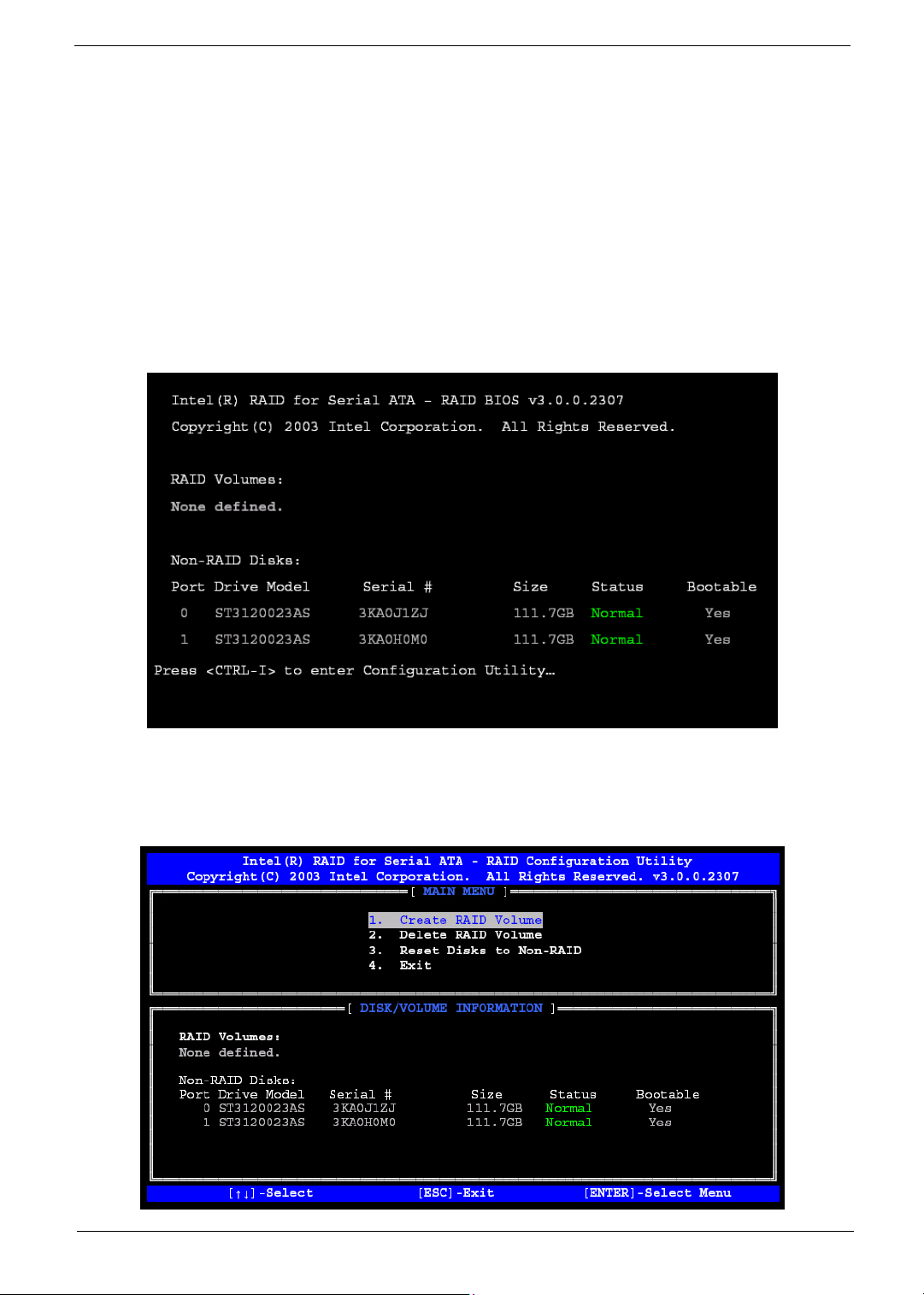
The Intel RAID Option ROM should be integrated with the system BIOS on all motherboards with a supported
Intel chipset. Please use
should appear early in system boot-up, during the POST (Power-On Self Test).
Using the Intel RAID Option ROM
1. Creating, Deleting and Resetting RAID Volumes:
The Serial ATA RAID volume may be configured using the RAID Configuration utility stored within the
Intel RAID Option ROM. During the Power-On Self Test (POST), the following message will appear for a
few seconds (Note: The “Driver Model”, “Serial #” and “Size” in the following example might be different
from your system.)
b+ <I> keys to enter the “Intel(R) RAID for Serial ATA” status screen, which
After the above message shows, press
Configuration Utility.
2. Creating, Deleting and Resetting RAID Volumes:
Chapter 2 56
band <I> keys simultaneously to enter the RAID
Page 66

(1) Create RAID Volume:
Select this option and press
Specify a RAID Volume name and then press the vor ekey to go to the next field.
e. The following screen appears:
Select the strip value for the RAID 0/1 array by scrolling through the available values by using the
wor y keys and pressing the ekey to select and advance to the next field.
The available values range from 4KB to 128 KB in power of 2 increments. The strip value should be
chosen based on the planned drive usage. Here are some suggested selections:
16 KB - Best for sequential transfers
64 KB - Good general purpose strip size
128 KB - Best performance for most desktops and workstations. The default value.
57 Chapter 2
Page 67

NOTE: RAID 1 can not select Strip Size.
From the Strip size, press the vor ekey to advance to the Create Volume prompt. The
window will appear as follows:
Then Press
Chapter 2 58
eto create the specified volume and the following prompt will show:
Page 68
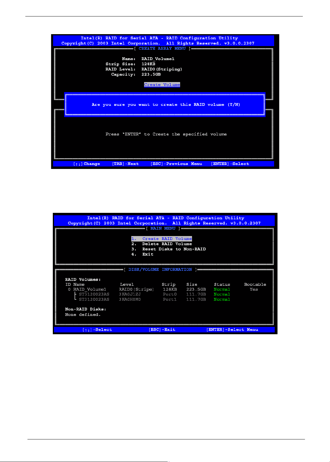
Press <Y> to confirm the selection or press <N> to create the RAID volume again.
Then you will return to the main menu with an updated status as follows:
Scroll to option 4 Exit and press eto exit the RAID Configuration utility. The following prompt
appears:
59 Chapter 2
Page 69
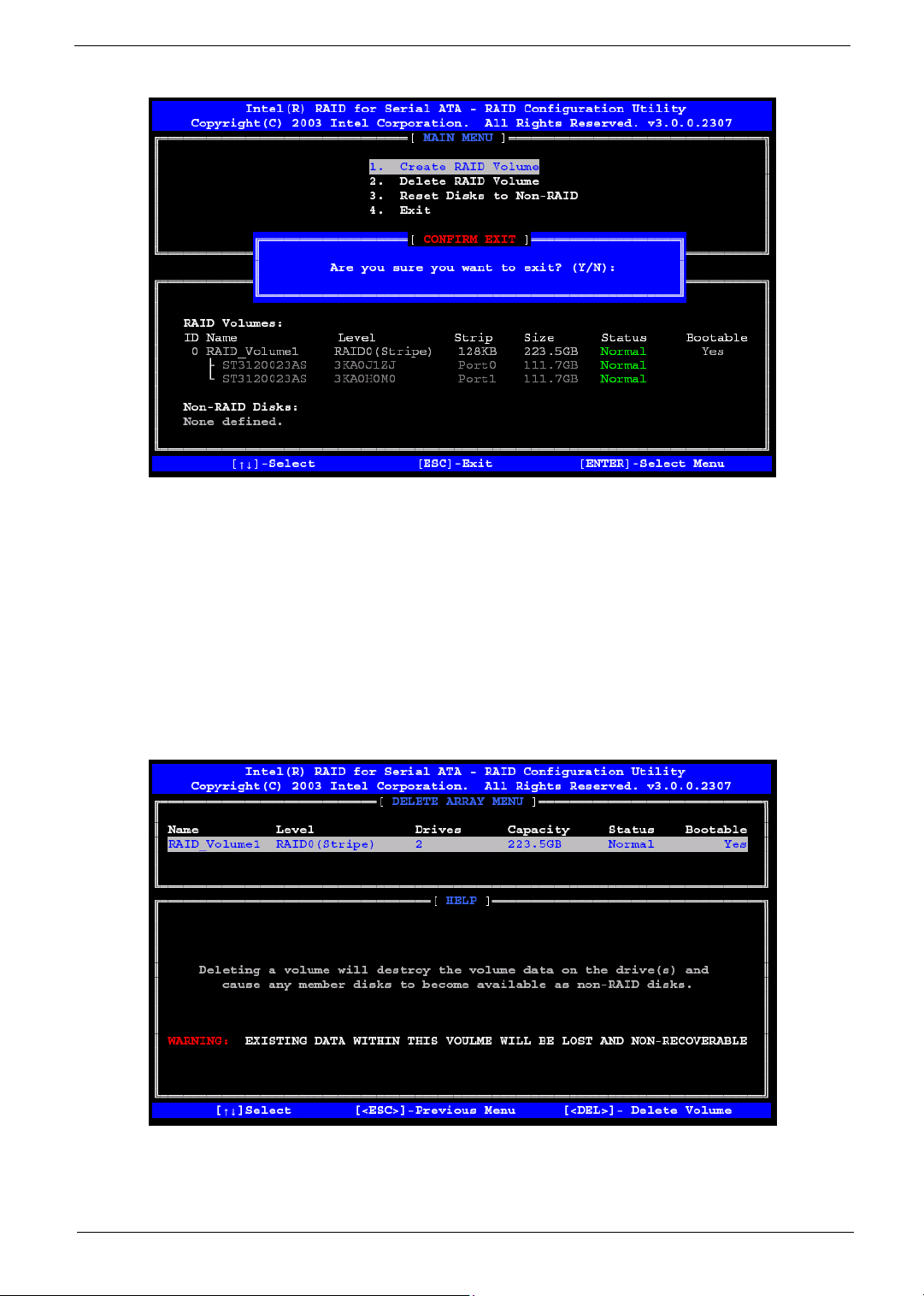
Click <Y> to confirm the exit.
(2) Delete RAID Volume:
Here you can delete the RAID volume, but please be noted that all data on RAID drives will be lost.
NOTE: If your system currently boots to RAID and you delete the RAID volume in the Intel RAID
Option ROM, your system will become unbootable.
Select option 2 Delete RAID Volume from the main menu window and press ekey to select a
RAID volume for deletion. The following window will appear:
Chapter 2 60
Page 70
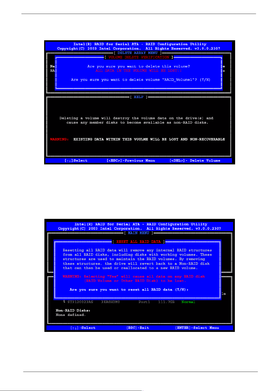
Select the volume and press ckey to delete the RAID volume. The following prompt appears:
Press <Y> key to accept the volume deletion.
(3) Reset Disks to Non-RAID:
Select option 3 Reset Disks to Non-RAID and press eto delete the RAID volume and remove
any RAID structures from the drives. The following screen appears:
Press <Y> key to accept the selection.
NOTE: You will lost all data on the RAID drives and any internal RAID structures when you perform
this operation. This operation may cause some issues such as incompatible RAID
configuration or a failed volume or failed disk.
61 Chapter 2
Page 71

RAID 0
RAID 0 uses an algorithm to break files into smaller files of the user defined size called the stripe size. Once a
file is broken down into these stripes, each drive in the array receives one or more of these fragments. For
example, if there are two drives in a RAID 0 array with a 64KB stripe size and the RAID controller gets a
command to write a single 128KB file, the file is broken down into two 64KB stripes. Next, one of the two
stripes is sent to disk 1 and the other to disk 2 simultaneously This completes the write process.
Naturally, this decreases the time required to write a file since more than one disk is working to store the
information. In our example above the time associated with writing our 128KB file turns out to be the time
required to write a single 64KB file, since this is what is what occurs simultaneously on both disks in the array.
The speed of reading a file back is also increased with a sufficiently large file. Let's use our 128KB file on a two
disk RAID 0 array with a 64KB stripe size for example again. After the data is stored on both drives in the
array, it can be read back by reading the two 64KB files from each drive at the same time. Thus, once again,
the time required to read back our 128KB file is actually only the time required to read a single 64KB file.
In some situations, when a file is smaller than the stripe, the file is not broken up and instead is written to the
array as is. This results in no speed improvement over a non RAID 0 setup because the drives on the array are
not working together when reading or writing.
At the same time, an extremely small stripe size makes a drive do more work than it can handle and can
significantly slow down RAID 0 performance as well. For example, if we had a 1KB stripe size and a 128KB
file, each drive would have to be written to 64 times to store 64 different 1KB files. This creates a bottleneck as
the drive attempts to read or write a large number of times for a single file.
As we mentioned before, RAID 0 has no fault tolerance, meaning that if one drive in the array fails, the whole
array is shot. There is no way to rebuild or repair the information stored on a RAID 0 array. This makes a RAID
0 is setup the most susceptible to failure RAID type, a fact that usually keeps users with sensitive data from
choosing RAID 0 as their RAID setup.
At the same time, however, RAID 0 is the fastest of all RAID setups. Since there is no overhead required to
store extra information for fault tolerance, the speed of RAID 0 can theoretically perform 2 times the speed of a
single drive when there are 2 drives in the array. Adding more drives only increases this theoretical
performance amount, so if you have a 6 drive RAID 0 array, performance could be as large as 6 times the
performance of a single drive.
Using different hard drives in a RAID 0 setup can result in two problems. First off, the size of the RAID array
will only be the size of the smallest drive multiplied by the number of drives in the array. This is because the
controller always writes to all the drives in the array and once one is filled no more information can be stored
on the array. Secondly, the speed of a RAID 0 setup is only as fast as the slowest drive in the array. Because
chunks of data are being written to the disks at the same time, if one drive is slower than the rest the others
must sit and wait for the slowest drive to finish. It is for these reasons that it is suggested that identical drives
be used on a RAID 0 setup.
What RAID 0 boils down to is speed and little more. The fact of the matter is that RAID 0 is not redundant at all,
just fast. But for many users, this is all that is important.
Chapter 2 62
Page 72

RAID 1
RAID 1 works by writing identical sets of information to two drives in an array. When the controller is sent a
64KB file to be written to a two disk RAID 1 array, the controller sends identical copies of this 64KB file to both
disks in the array. Reads are the same as on a single drive: the controller requests the file from one of the two
drives.
The special feature of RAID 1 is its fault tolerance. If either of the two drives in the array fails, no data is lost. If/
when a drive fails, the RAID controller simply uses the information off of the drive that is still available. When a
new drive is added to the array to fix the failed one, a mirroring occurs in which the data from the good drive is
written to the new drive to recreate the array again.
As one could suspect, RAID 1 offers very little in terms of performance. When requesting data from a drive,
some RAID controllers take information from the drive that is not busy or closer to the desired information,
theoretically resulting in faster data access. When writing, on the other hand, there is some overhead when
compared to a single drive as the controller must duplicate the file it is sent and then pass it along to the drives.
In a RAID 1 setup, identical drives are best in order to prevent lost space. Since the same data is being written
to two drives, the size of the RAID 1 array is equal to the size of the smallest drive in the array. For example, if
a 20GB drive and a 30GB drive are used in a RAID 1 setup, the array would only be 20GB with the 10 extra
gigabytes on the 30GB drive going to waste. The performance difference between two drives is also an issue
here, since a faster drive would have to wait for a slower drive before it could write more information.
RAID 1 is a good solution for those looking for security over speed. Although not the slowest of the common
RAID types, RAID 1 can be slower than a single drive in some cases (more on that in the benchmarks). What
RAID 1 does provide is a very safe environment, where failure of a single drive does not equate to any down
time.
63 Chapter 2
Page 73

Chapter 3
Machine Disassembly and Replacement
This chapter contains step-by-step procedures on how to disassemble the Veriton 7600GTR/GT/V, 5600GT/V
and 3600GT/V desktop computer for maintenance and troubleshooting.
To disassemble the computer, you need the following tools:
! Wrist grounding strap and conductive mat for preventing electrostatic discharge
! Flat-bladed screwdriver
! Phillips screwdriver
! Hexagonal screwdriver
! Plastic stick
NOTE: The screws for the different components vary in size. During the disassembly process, group the
screws with the corresponding components to avoid mismatches when putting back the components.
Chapter 3 64
Page 74

General Information
Before You Begin
Before proceeding with the disassembly procedure, make sure that you do the following:
1. Turn off the power to the system and all peripherals.
2. Unplug the AC adapter and all power and signal cables from the system.
Chapter 3 65
Page 75
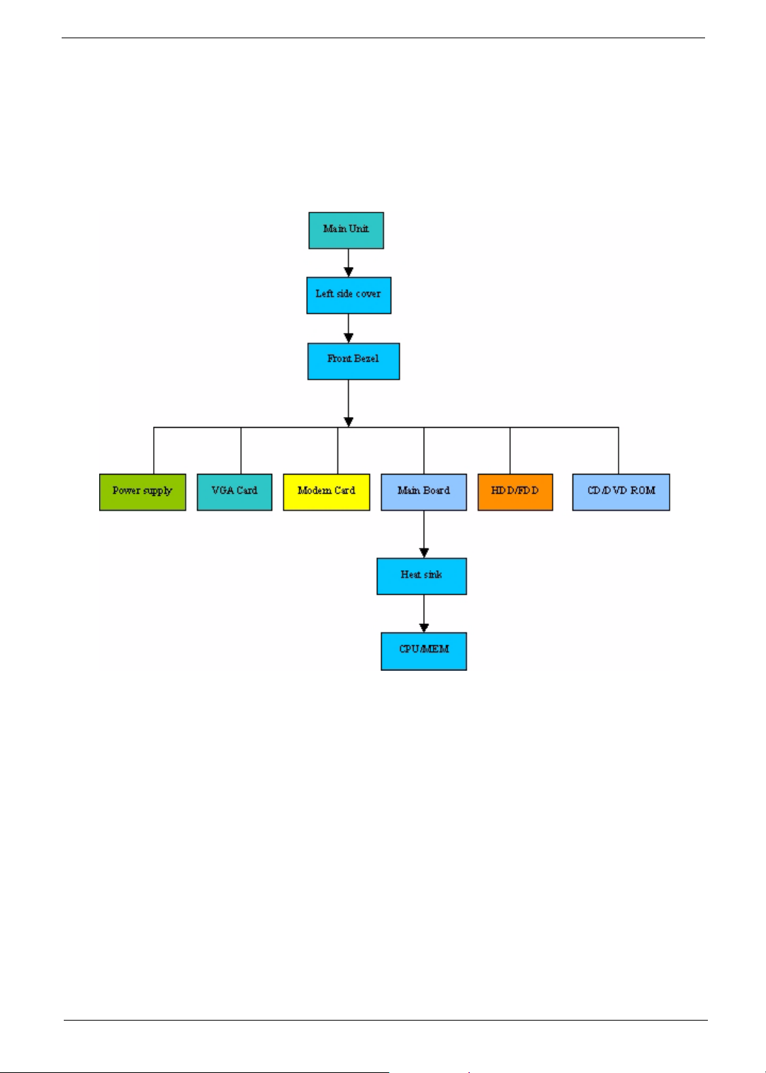
Disassembly Procedure Flowchart
The flowchart on the succeeding page gives you a graphical representation on the entire disassembly
sequence and instructs you on the components that need to be removed during servicing.
Veriton 7600GTR/GT/V
66 Chapter 3
Page 76
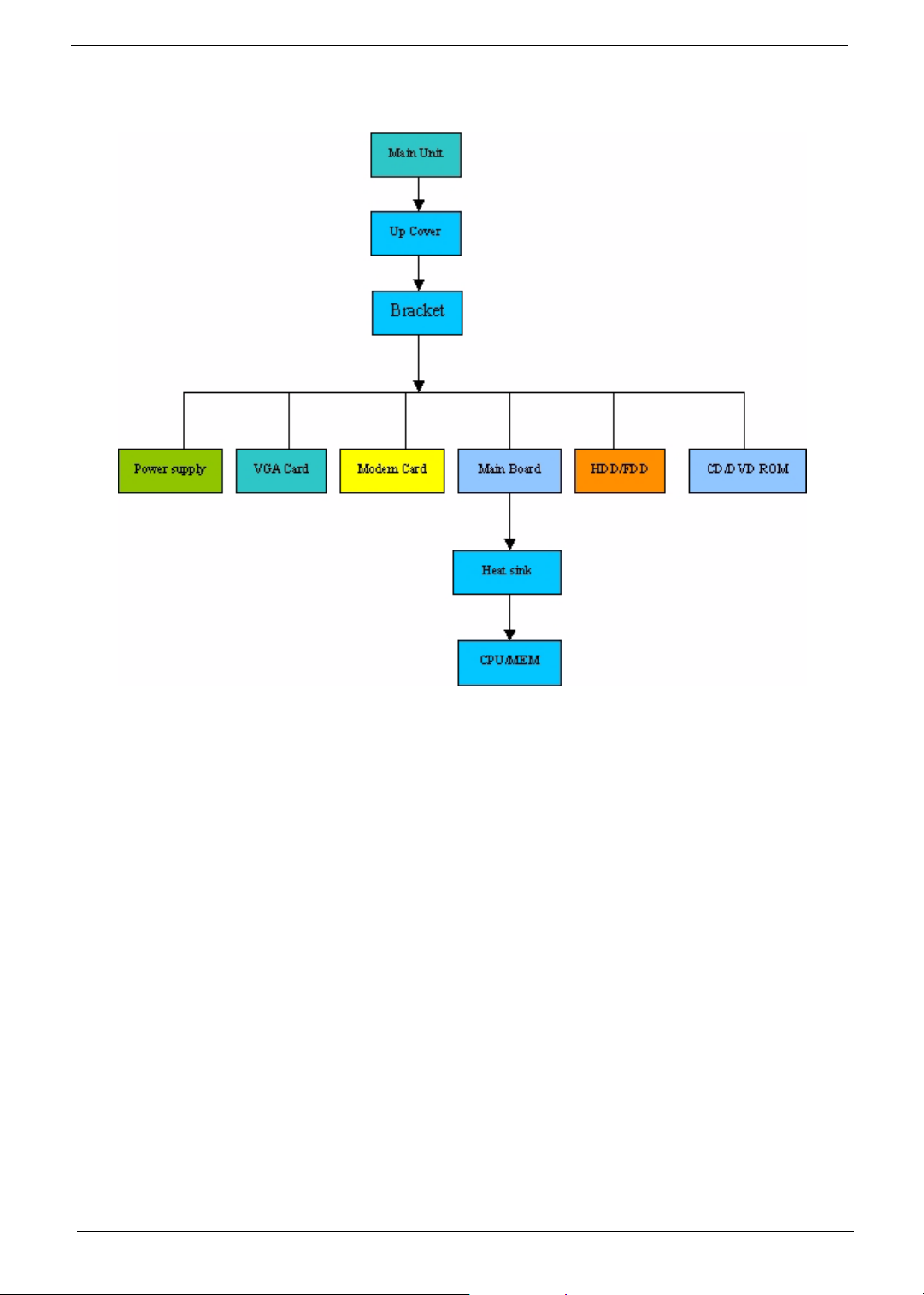
Veriton 5600GT/V
Chapter 3 67
Page 77

Veriton 3600GT/V
68 Chapter 3
Page 78

Disassembling the Veriton 7600GTR/GT/V
Opening the Housing
This section tells you how to open the housing cover when you need to install additional components inside
the system unit.
CAUTION: Before you proceed, make sure that you have turned off the system and all peripherals connected
to it.
Removing the Housing
1. Turn off the system power and unplug all cables.
2. Remove the two screws holding the upper cover
3. Slide the left cover out and then gently pull it outward to detach it from the housing.
.
Removing the Front Panel
1. Remove the front panel as the picture shows carefully.
.
Removing the ODD/FDD/HDD
1. Disconnect the ODD power cable and ODD cable from the ODD.
.
2. Disconnect the FDD cable and FDD power cable from the FDD.
Chapter 3 69
Page 79
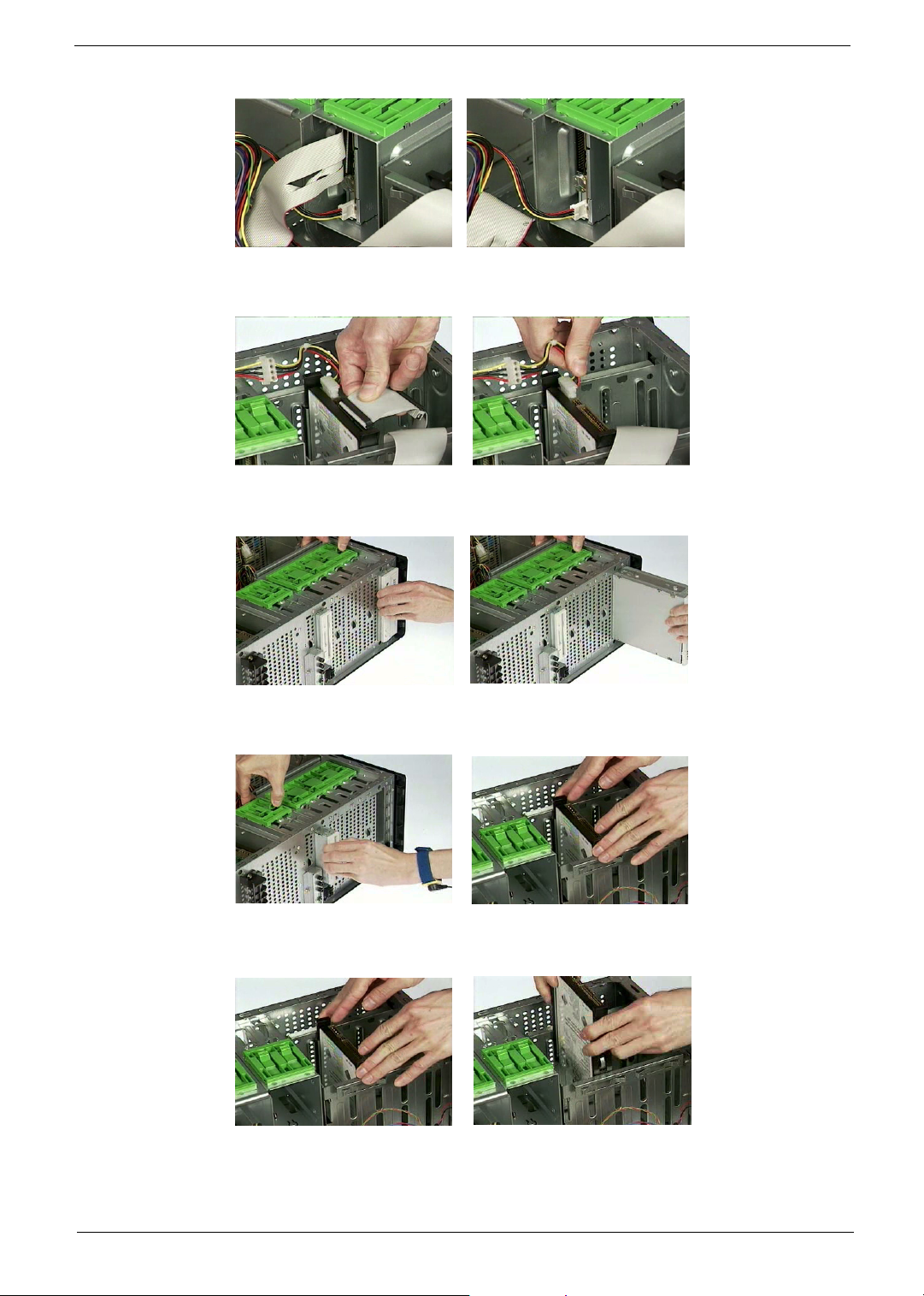
.
3. Disconnect the HDD cable and HDD power cable from the HDD.
4. Pull the ODD lock and then detach the ODD from the frame.
5. Pull the FDD lock and then detach the FDD from the frame.
6. Press the right and left HDD holders and then detach the HDD carefully.
7. Remove the left ODD holder.
8. Remove the left FDD holder.
9. Remove the left and right HDD holders.
70 Chapter 3
Page 80
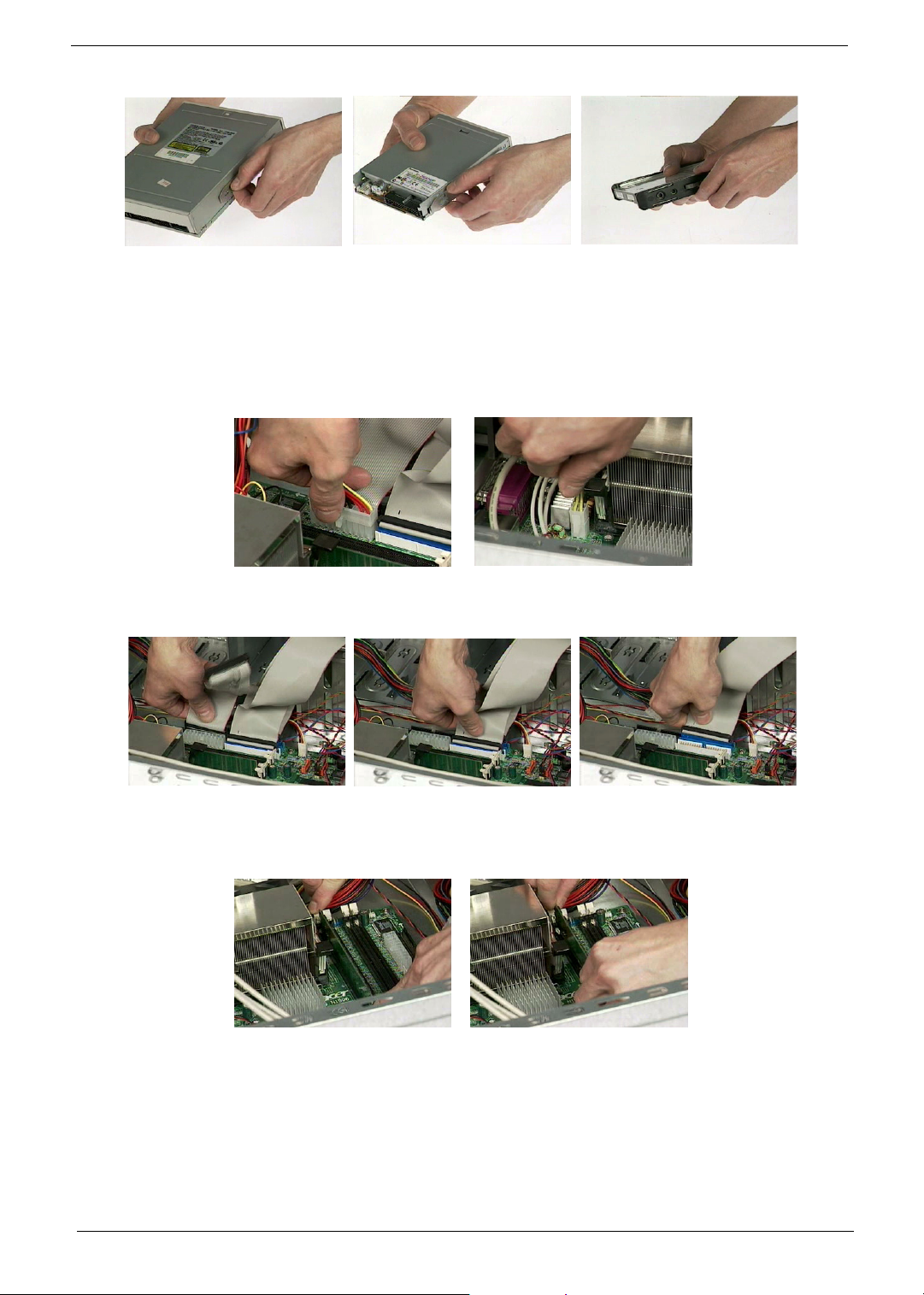
Removing the Internal Cables/Connectors and Memory
1. Disconnect the main power connector from the main board.
2. Disconnect the 12-voltage power connector from the main board.
.
3. Disconnect the FDD cable, ODD cable and HDD cable from the main board.
4. Press the leavers on the both sides of the DIMM socket outward to release the DIMM, and then gently pull
the DIMM out to remove it.
5. Disconnect the front panel audio connector from the main board.
6. Disconnect the two front USB connectors from the main board.
Chapter 3 71
Page 81
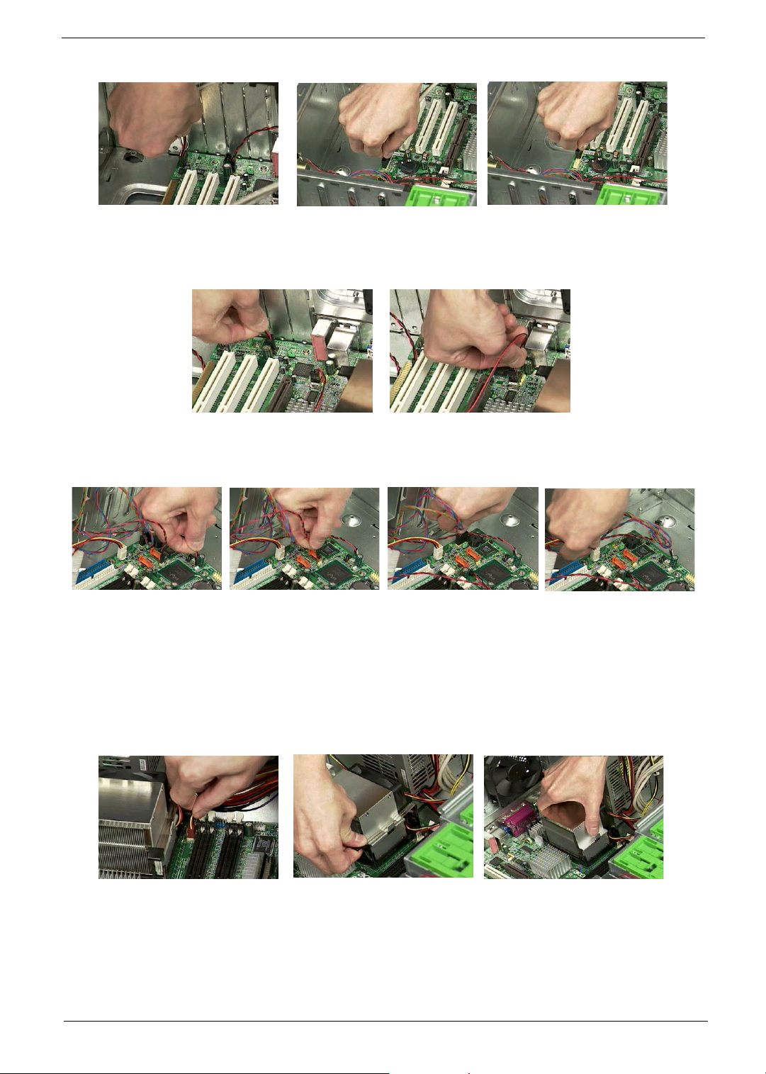
7. Disconnect the internal speaker connector from the main board.
8. Disconnect the LAN LED connector from the main board.
9. Disconnect the one button recovery connector, chassis intrusion switch connector, front panel connectors,
and system fan connector from the main board.
Removing the CPU Fan Sink, CPU and System Fan
1. Disconnect the CPU fan connector from the main board.
2. Remove the two latches on both side of the fan sink.
3. Remove the CPU fan sink from the main board.
4. Pull the socket lever up to 90 degree and then pull out the CPU from the socket.
5. Put the socket lever back to the original position.
72 Chapter 3
Page 82
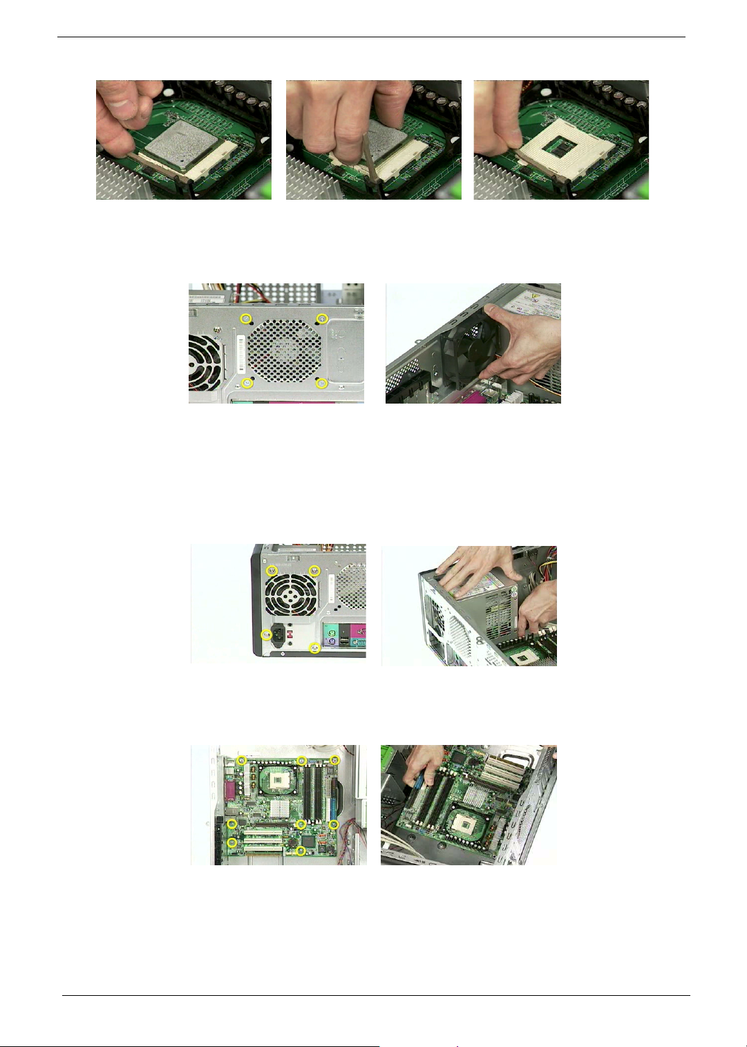
6. Remove the four screws holding the system fan.
7. Take out the system fan.
Removing the Power Supply and Main Board
1. Remove the four screws holding the power supply on the rear side.
2. Detach the power supply from the housing carefully.
3. Remove the eight screws holding the main board as the picture shows.
4. Detach the main board from the lower case carefully.
.
Removing the Upper Cover and Daughter Board Module
1. Remove the two screws holding the upper cover as the picture shows.
2. Cut the cable clamp with the tweezers.
Chapter 3 73
Page 83
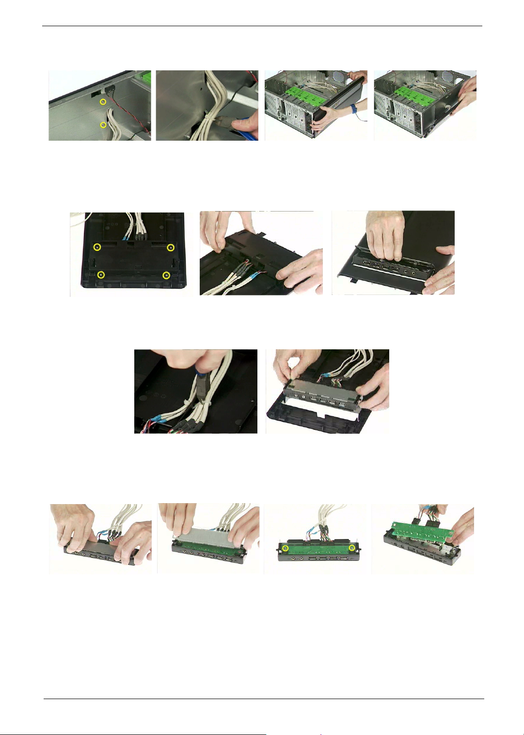
3. Detach the upper cover from the housing carefully.
4. Remove the four screws holding the daughter board plate.
5. Remove the daughter board plate.
6. Remove the daughter board top cover as the picture shows.
.
7. Cut the cable clamp holding the two front USB cables and front panel audio cable.
8. Remove the daughter board module from the upper cover.
.
9. Remove the daughter board plate from the daughter board module.
10. Remove the two screws holding the daughter board.
11. Remove the daughter board.
12. Disconnect the front panel audio connector from the daughter board.
13. Disconnect the two front USB connectors from the daughter board.
74 Chapter 3
Page 84

Removing the Intrusion Alarm and LCD Module
1. Remove the two screws holding the intrusion alarm, and then take out the intrusion alarm
.
2. Remove one screw holding the LED module holder.
3. Remove the LED module as the picture shows.
.
4. Remove one screw holding the reset button holder as the picture shows.
5. Pull out the reset cable carefully.
.
Chapter 3 75
Page 85
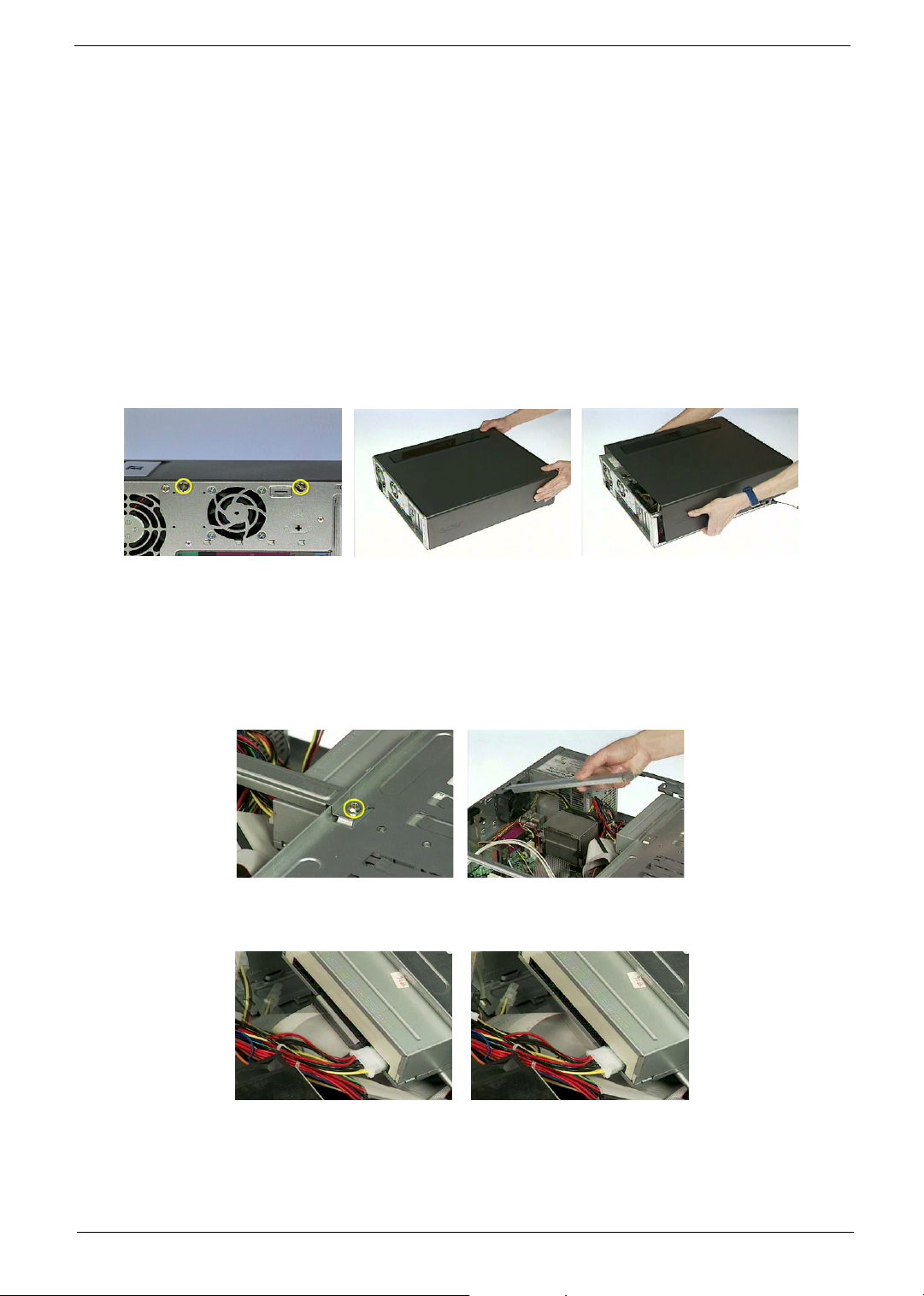
Disassembling the Veriton 5600GT/V
Opening the Housing
This section tells you how to open the housing cover when you need to install additional components inside
the system unit.
CAUTION: Before you proceed, make sure that you have turned off the system and all peripherals connected
to it.
Removing the Housing
1. Remove the two screws holding the upper cover.
2. Slide the upper cover out and then gently pull it outwar d to detach it from the housing.
.
Removing the ODD/FDD/HDD
1. Remove one screw holding the bracket holder.
2. Remove the bracket holder as the picture shows.
3. Disconnect the ODD cable and ODD power cable from the ODD.
4. Pull the ODD lock and then detach the ODD from the frame.
76 Chapter 3
Page 86

.
5. Disconnect the FDD power cable and FDD cable from the FDD.
6. Pull the FDD lock and then detach the FDD from the frame.
.
7. Disconnect the HDD cable and HDD power cable from the HDD.
8. Press the right and left HDD holders and then detach the HDD carefully.
9. Remove the right ODD holder.
10. Remove the left FDD holder.
11. Remove the left and right HDD holders.
Chapter 3 77
Page 87
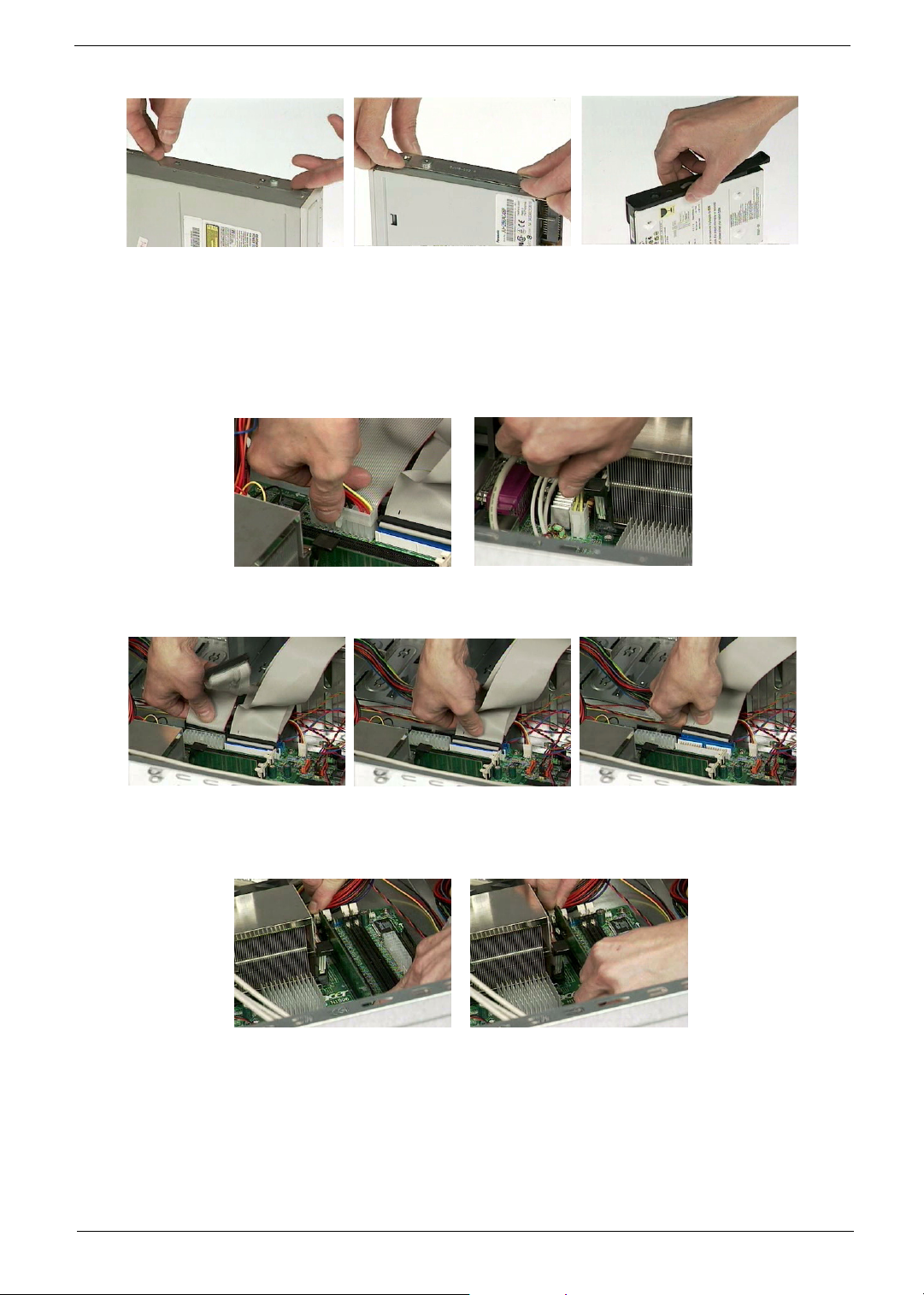
Removing the Internal Cables/Connectors and Memory
1. Disconnect the main power connector from the main board.
2. Disconnect the 12-voltage power connector from the main board.
.
3. Disconnect the FDD cable, ODD cable and HDD cable from the main board.
4. Press the leavers on the both sides of the DIMM socket outward to release the DIMM, and then gently pull
the DIMM out to remove it.
Removing the CPU Fan Sink and CPU
1. Disconnect the CPU fan connector from the main board.
2. Remove the two latches on both side of the fan sink.
3. Remove the CPU fan sink from the main board.
78 Chapter 3
Page 88
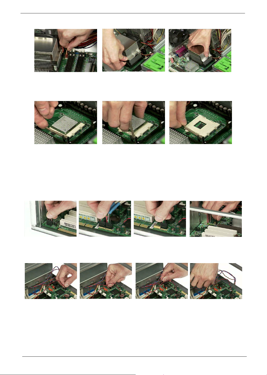
4. Pull the socket lever up to 90 degree and then pull out the CPU from the socket.
5. Put the socket lever back to the original position.
Removing the Internal Cables/Connectors and Memory
1. Disconnect the front panel audio connector from the main board.
2. Disconnect the two front USB connectors from the main board.
3. Disconnect the LAN LED connector from the main board.
4. Disconnect the one button recovery connector, chassis intrusion switch connector, front panel connectors,
and system fan connector from the main board.
Removing the System Fan, Power Supply and Main Board
1. Remove the four screws holding the system fan.
2. Take out the system fan.
Chapter 3 79
Page 89

3. Remove the four screws holding the power supply on the rear side.
4. Detach the power supply from the housing carefully.
.
5. Remove the eight screws holding the main board as the picture shows.
6. Detach the main board from the lower case carefully.
.
Removing the LED Module and Daughter Board Module
1. Remove one screw holding the LED module holder.
2. Remove the LED module as the picture shows.
3. Remove the two screws holding the intrusion alarm, and then take out the intrusion alarm.
80 Chapter 3
Page 90
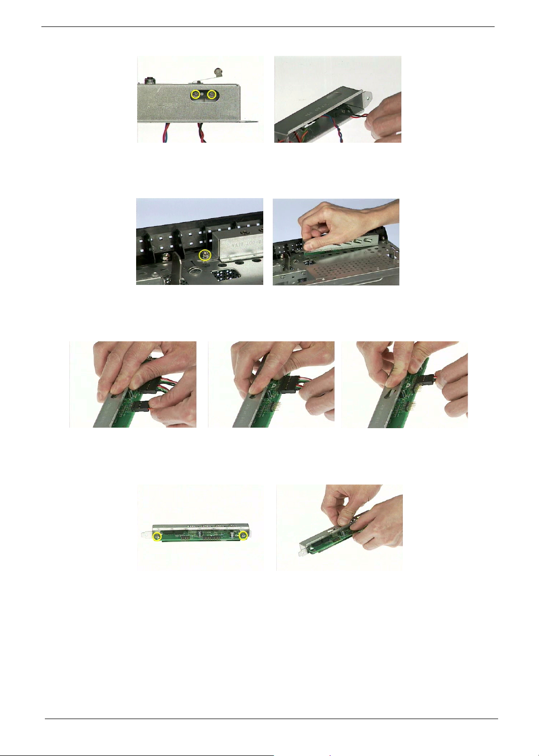
4. Remove one screw holding the daughter board bracket.
5. Remove the daughter board module as the picture shows.
.
6. Disconnect the front panel audio connector from the daughter board.
7. Disconnect the two front USB connectors from the daughter board.
.
8. Remove the two screws holding the daughter board.
9. Remove the daughter board from the daughter board bracket.
Chapter 3 81
Page 91
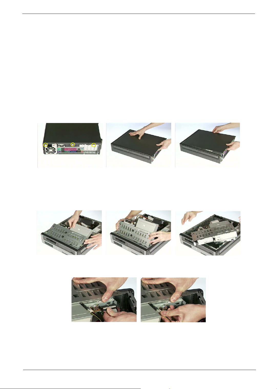
Disassembling the Veriton 3600GT/V
Opening the Housing
This section tells you how to open the housing cover when you need to install additional components inside
the system unit.
CAUTION: Before you proceed, make sure that you have turned off the system and all peripherals connected
to it.
Removing the Housing
1. Remove the three screws holding the upper cover.
2. Slide the left cover out and then gently pull it outward to detach it from the housing.
.
Removing the FDD/ODD/HDD
1. Lift up the FDD/HDD/ODD frame carefully.
2. Disconnect the FDD cable and FDD power cable from the FDD.
3. Disconnect the ODD cable and ODD power cable from the ODD.
82 Chapter 3
Page 92

.
4. Disconnect the HDD cable and HDD power cable from the HDD.
5. Pull the ODD lock and then detach the ODD from the frame.
.
6. Pull the FDD lock and then detach the FDD from the frame.
7. Press the right and left HDD holders and then detach the HDD carefully.
8. Remove the left ODD holder.
9. Remove the left FDD holder.
10. Remove the left and right HDD holders.
Chapter 3 83
Page 93
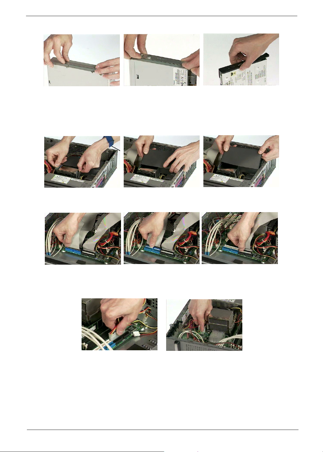
Removing the Internal Cables/Connectors and Memory
1. Remove the air duck as the video shows.
2. Disconnect the HDD cable, ODD cable, and FDD cable from the main board.
3. Disconnect the main power connector from the main board.
4. Disconnect the 12-voltage power connector from the main board.
.
5. Press the leavers on the both sides of the DIMM socket outward to release the DIMM, and then gently pull
the DIMM out to remove it.
84 Chapter 3
Page 94

Removing the Internal Cables/Connectors
1. Disconnect the front panel audio connector from the main board.
2. Disconnect the two front USB connectors from the main board.
3. Disconnect the LAN LED connector from the main board.
4. Disconnect the internal speaker connector from the main board.
5. Disconnect the one button recovery connector, chassis intrusion switch connector, front panel connectors,
and system fan connector from the main board.
Removing the CPU Fan Sink and CPU
1. Disconnect the CPU fan connector from the main board.
2. Remove the two latches on both side of the fan sink.
3. Remove the CPU fan sink from the main board.
Chapter 3 85
Page 95

4. Pull the socket lever up to 90 degree and then pull out the CPU from the socket.
5. Put the socket lever back to the original position.
Removing the System Fan and Main Board
1. Remove the two screws holding the system fan.
2. Take out the system fan.
3. Remove the eight screws holding the main board as the picture shows.
4. Detach the main board from the lower case carefully.
.
Removing the Intrusion Alarm, Daughter Board Module and LCD Module
1. Remove the two screws holding the intrusion alarm, and then take out the intrusion alarm.
86 Chapter 3
Page 96
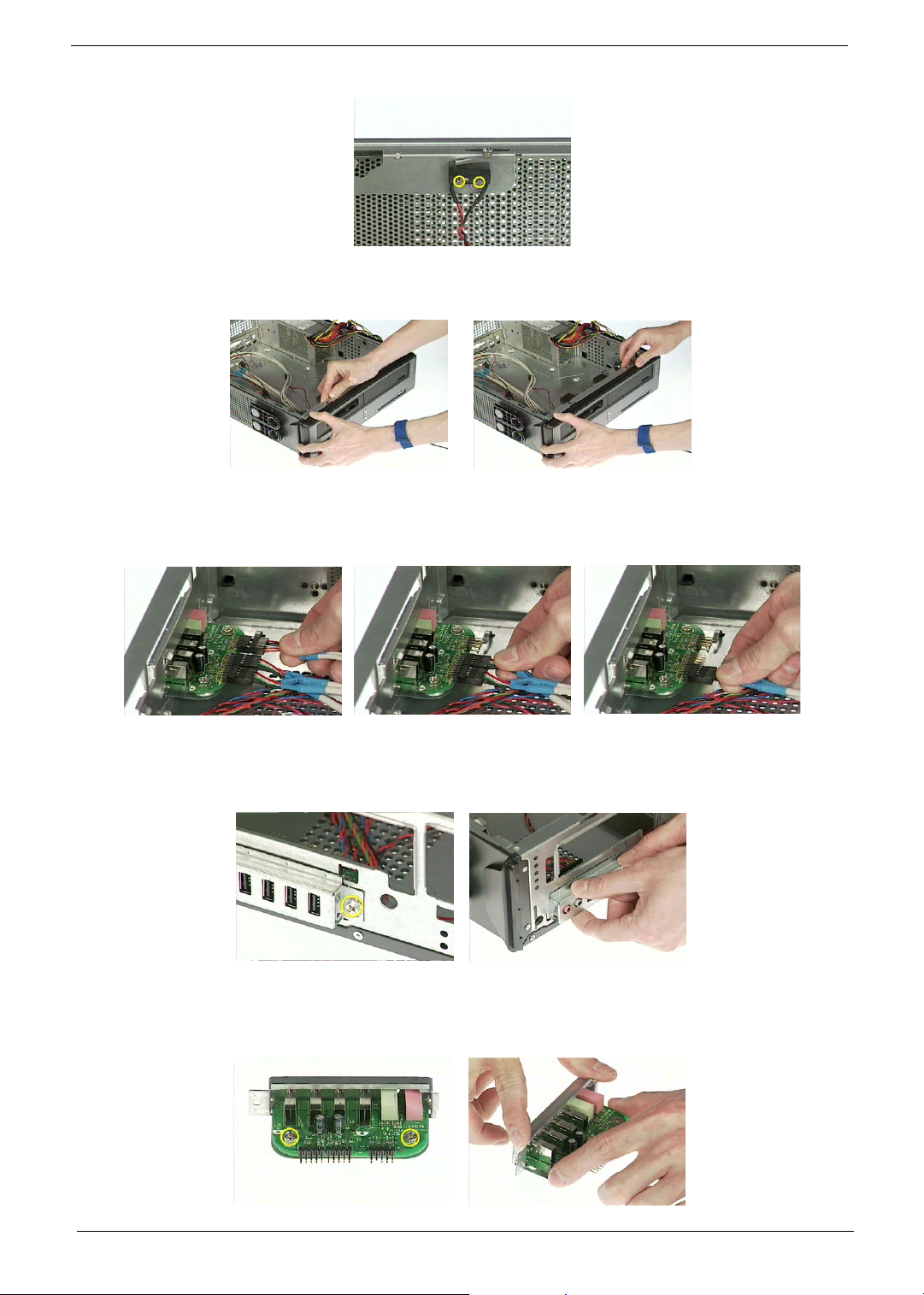
.
2. Remove the front panel as the video shows.
3. Disconnect the front panel audio connector from the daughter board.
4. Disconnect the two front USB connectors from the daughter board.
.
5. Remove one screw holding the daughter board bracket.
6. Remove the daughter board module as the video shows.
.
7. Remove the two screws holding the daughter board.
8. Remove the daughter board from the daughter board bracket.
.
Chapter 3 87
Page 97
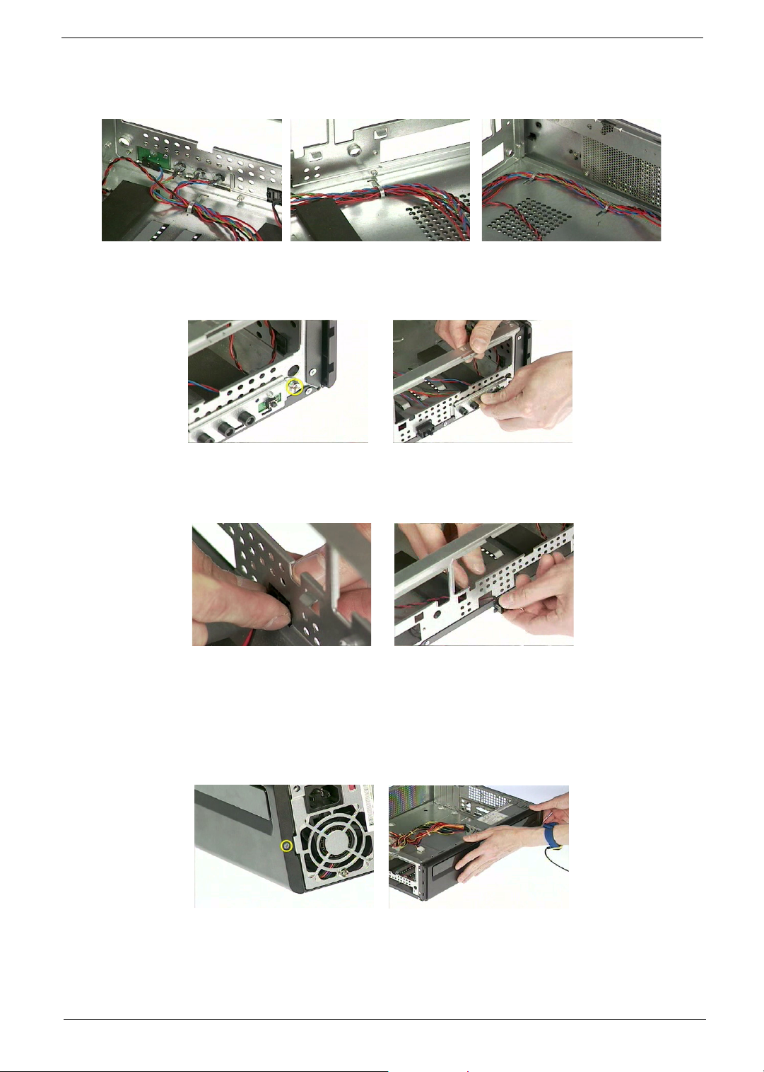
9. Pull the internal speaker cable, front panel cables, LAN LED cable and one button recovery cable as the
video shows.
.
10. Remove one screw holding the LED module holder.
11. Remove the LED module as the video shows.
.
12. Remove the reset button as the video shows.
13. Pull out the reset cable carefully.
.
Removing the Upper Case and Power supply
1. Remove one screw holding the upper cover.
2. Remove the upper cover as the video shows.
3. Remove one screw holding the power supply as the video shows.
4. Remove the two screws holding the power supply on the rear side.
5. Remove the power supply bracket.
6. Detach the power supply from the housing carefully.
88 Chapter 3
Page 98
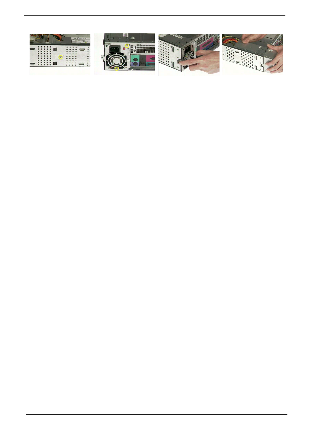
Chapter 3 89
Page 99

Troubleshooting
This chapter provides troubleshooting information for the Veriton 7600GTR/7600G T/7600V, 5600GT/5600V
and 3600GT/3600V.
! Power-On Self-Test (POST)
! Index of Error Message
! Index of Error Symptoms
! Undetermined Problems
Chapter 4
Chapter 4 90
Page 100
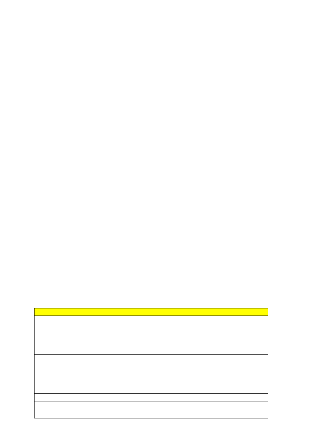
Power-On Self-Test (POST)
Each time you turn on the system, the Power-on Self Test (POST) is initiated. Several items are tested during
POST, but is for the most part transparent to the user.
The Power-On Self Test (POST) is a BIOS procedure that boots the system, initializes and diagnoses the
system components, and controls the operation of the power-on password option. If POST discovers errors in
system operations at power-on, it displays error messages on screen, generates a check point code at port
80h or even halts the system if the error is fatal.
The main components on the main board that must be diagnosed and/or initialized by POST to ensure system
functionality are as follows:
! Microprocessor with built-in numeric co-processor and cache memory subsystem
! Direct Memory Access (DMA) c ontroller
! Interrupt system
! Three programmable timers
! ROM subsystem
! RAM subsystem
! CMOS RAM subsystem and real time clock/calendar with battery backup
! Onboard parallel interface controller
! Embedded hard disk interface and one diskette drive interface
! Keyboard and auxiliary device controllers
! 1.44M floppy controller
! I/O ports
! One parallel port
! One PS/2-compatible mouse port
! One PS/2-compatible keyboard port
NOTE: When Post executes a task, it uses a series of preset numbers called check points to be latched at
port 80h, indicating the stages it is currently running. This latch can be read and shown on a debug board.
The following table describes the BIOS common tasks carried out by POST. Each task is denoted by an
unique check point number. For other unique check point numbers that are not listed in the table, refer to the
corresponding product service guide.
Post Checkpoints List: The list may vary accordingly depending on your BIOS
.
Checkpoint Description
CFh Test CMOS R/W functionality
C0h Early chipset initialization:
-Disable shadow RAM
-Disable L2 cache (socket 7 or below)
-Program basic chipset registers
C1h Detect memory
-Auto-detection of DRAM size, type and ECC.
-Auto-detection of L2 cache (socket 7 or below)
C3h Expand compressed BIOS code to DRAM
C5h Call chipset hook to copy BIOS back to E000 & F000 shadow RAM.
01h Expand the Xgroup codes locating in physical address 1000:0
02h Reserved
03h Initial Superio_Early _Init switch
91 Chapter 4
 Loading...