

Page 1

Veriton 3300
User’s guide
Page 2

Copyright © 2001 Acer Incorporated
All Rights Reserved.
Veriton 3300
User’s guide
Changes may be made periodically to the information in this publication without obligation
to notify any person of such revision or changes. Such changes will be incorporated in new
editions of this manual or supplementary documents and publications. This company makes
no representations or warranties, either expressed or implied, with respect to the contents
hereof and specifically disclaims the implied warranties of merchantability or fitness for a
particular purpose.
Record the model number, serial number, purchase date, and place of purchase information in
the space provided below. The serial number and model number are recorded on the label
affixed to your computer. All correspondence concerning your unit should include the serial
number, model number, and purchase information.
No part of this publication may be reproduced, stored in a retrieval system, or transmitted, in
any form or by any means, electronic, mechanical, photocopy, recording, or otherwise,
without the prior written permission of Acer Incorporated.
Model Number : _________________________________
Serial Number: ___________________________________
Purchase Date: ___________________________________
Place of Purchase: ________________________________
Acer and the Acer Logo are registered trademarks of Acer Inc. Other company’s product
names or trademarks are used herein for identification purposes only and belong to their
respective companies.
Page 3

Notices
FCC notice
This device has been tested and found to comply with the limits for a
Class B digital device pursuant to Part 15 of the FCC Rules. These limits
are designed to provide reasonable protection against harmful
interference in a residential installation. This device generates, uses,
and can radiate radio frequency energy and, if not installed and used
in accordance with the instructions, may cause harmful interference to
radio communications.
However, there is no guarantee that interference will not occur in a
particular installation. If this device does cause harmful interference to
radio or television reception, which can be determined by turning the
device off and on, the user is encouraged to try to correct the
interference by one or more of the following measures:
• Reorient or relocate the receiving antenna
• Increase the separation between the device and receiver
• Connect the device into an outlet on a circuit different from that
to which the receiver is connected
• Consult the dealer or an experienced radio/television technician
for help
iii
Notice: Shielded cables
All connections to other computing devices must be made using
shielded cables to maintain compliance with FCC regulations.
Notice: Peripheral devices
Only peripherals (input/output devices, terminals, printers, etc.)
certified to comply with the Class B limits may be attached to this
equipment. Operation with noncertified peripherals is likely to result
in interference to radio and TV reception.
Caution! Changes or modifications not expressly approved by
the manufacturer could void the user’s authority, which is granted
by the Federal Communications Commission, to operate this
computer.
Page 4

iv
Use conditions
This part complies with Part 15 of the FCC Rules. Operation is subject
to the following two conditions: (1) this device may not cause harmful
interference, and (2) this device must accept any interference received,
including interference that may cause undesired operation.
Notice: Canadian users
This Class B digital apparatus meets all requirements of the Canadian
Interference-Causing Equipment Regulations.
Remarque à l’intention des utilisateurs canadiens
Cet appareil numérique de la classe B respected toutes les exigences du
Règlement sur le matériel brouilleur du Canada.
Important safety instructions
Read these instructions carefully. Save these instructions for future
reference.
1. Follow all warnings and instructions marked on the product.
2. Unplug this product from the wall outlet before cleaning. Do not
use liquid cleaners or aerosol cleaners. Use a damp cloth for
cleaning.
3. Do not use this product near water.
4. Do not place this product on an unstable cart, stand, or table. The
product may fall, causing serious damage to the product.
5. Slots and openings in the cabinet and the back or bottom are
provided for ventilation; to ensure reliable operation of the
product and to protect it from overheating, these openings must
not be blocked or covered. The openings should never be blocked
by placing the product on a bed, sofa, rug, or other similar surface.
This product should never be placed near or over a radiator or
heat register, or in a built-in installation unless proper ventilation
is provided.
6. This product should be operated from the type of power indicated
on the marking label. If you are not sure of the type of power
available, consult your dealer or local power company.
7. Do not allow anything to rest on the power cord. Do not locate
this product where persons will walk on the cord.
Page 5

8. If an extension cord is used with this product, make sure that the
total ampere rating of the equipment plugged into the extension
cord does not exceed the extension cord ampere rating. Also,
make sure that the total rating of all products plugged into the
wall outlet does not exceed the fuse rating.
9. Never push objects of any kind into this product through cabinet
slots as they may touch dangerous voltage points or short out
parts that could result in a fire or electric shock. Never spill liquid
of any kind on the product.
10. Do not attempt to service this product yourself, as opening or
removing covers may expose you to dangerous voltage points or
other risks. Refer all servicing to qualified service personnel.
11. Unplug this product from the wall outlet and refer servicing to
qualified service personnel under the following conditions:
a. When the power cord or plug is damaged or frayed
b. If liquid has been spilled into the product
c. If the product has been exposed to rain or water
d. If the product does not operate normally when the operating
instructions are followed. Adjust only those controls that are
covered by the operating instructions since improper
adjustment of other controls may result in damage and will
often require extensive work by a qualified technician to
restore the product to normal condition.
e. If the product has been dropped or the cabinet has been
damaged
f. If the product exhibits a distinct change in performance,
indicating a need for service.
12. Replace the battery with the same type as the product's battery we
recommend. Use of another battery may present a risk of fire or
explosion. Refer battery replacement to a qualified serviceman.
13. Warning! Batteries may explode if not handled properly. Do not
disassemble or dispose of them in fire. Keep them away from
children and dispose of used batteries promptly.
14. Use only the proper type of power supply cord set (provided in
your accessories box) for this unit. It should be a detachable type:
UL listed/CSA certified, type SVT, rated 7A 125V minimum, VDE
approved or its equivalent. Maximum length is 15 feet (4.6
meters).
v
Page 6

vi
Laser compliance statement
The CD or DVD drive in this computer is a laser product. The CD or
DVD drive’s classification label (shown below) is located on the drive.
CLASS 1 LASER PRODUCT
CAUTION: INVISIBLE LASER RADIATION WHEN OPEN. AVOID
EXPOSURE TO BEAM.
APPAREIL A LASER DE CLASSE 1 PRODUIT
LASERATTENTION: RADIATION DU FAISCEAU LASER INVISIBLE EN CAS
D’OUVERTURE. EVITTER TOUTE EXPOSITION AUX RAYONS.
LASER KLASSE 1
VORSICHT: UNSICHTBARE LASERSTRAHLUNG, WENN ABDECKUNG
GEÖFFNET, NICHT DEM STRAHLL AUSSETZEN
PRODUCTO LÁSER DE LA CLASE I
ADVERTENCIA: RADIACIÓN LÁSER INVISIBLE AL SER ABIERTO. EVITE
EXPONERSE A LOS RAYOS.
ADVARSEL: LASERSTRÅLING VEDÅBNING SE IKKE IND I STRÅLEN
VARO! LAVATTAESSA OLET ALTTINA LASERSÅTEILYLLE.
VARNING: LASERSTRÅLNING NÅR DENNA DEL ÅR ÖPPNAD ÅLÅ
TUIJOTA SÅTEESEENSTIRRA EJ IN I STRÅLEN
VARNING: LASERSTRÅLNING NAR DENNA DEL ÅR ÖPPNADSTIRRA EJ
IN I STRÅLEN
ADVARSEL: LASERSTRÅLING NAR DEKSEL ÅPNESSTIRR IKKE INN I
STRÅLEN
Lithium battery statement
CAUTION
Danger of explosion if battery is incorrectly replaced. Replace only
with the same or equivalent type recommended by the manufacturer.
Discard used batteries according to the manufacturer’s instructions.
ADVARSEL!
Lithiumbatteri - Eksplosionsfare ved fejlagtig håndtering. Udskiftning
må kun ske med batteri af samme fabrikat og type. Léver det brugte
batteri tilbage til leverandøren.
Page 7

ADVARSEL
Eksplosjonsfare ved feilaktig skifte av batteri. Benytt samme
batteritype eller en tilsvarende type anbefalt av apparatfabrikanten.
Brukte batterier kasseres i henhold til fabrikantens instruksjoner.
VARNING
Explosionsfara vid felaktigt batteribyte. Anvãnd samma batterityp
eller en ekvivalent typ som rekommenderas av apparattillverkaren.
Kassera anvãnt batteri enligt fabrikantens instruktion.
VAROITUS
Päristo voi räjähtää, jos se on virheellisesti asennettu. Vaihda paristo
ainoastaan laitevalmistajan suosittelemaan tyyppiin. Hävitä käytetty
paristo valmistajan ohjeiden mukaisesti.
VORSICHT!
Explosionsgefahr bei unsachgemäßen Austausch der Batterie Ersatz
nur durch denselben oder einem vom Hersteller empfohlenem
ähnlichen Typ. Entsorgung gebrauchter Batterien nach Angaben des
Herstellers.
vii
Page 8

viii
Page 9

Notices iii
1 First things first 1
Package contents 3
Taking care of your computer 4
Important tips 4
Cleaning and servicing 4
Asking for technical assistance 5
Accessing the online guide 6
2 System tour 7
Features 9
Performance 9
Multimedia 9
Connectivity 9
Front panel 10
Rear panel 12
Keyboard 14
Mouse 17
Disk drives 18
Floppy drive 18
CD-ROM/DVD-ROM/CD-RW drive 19
Hard disk 21
3 Setting up your computer 23
Arranging a comfortable work area 25
Adjusting your chair 25
Positioning your Veriton PC 25
Positioning your monitor 27
Positioning your keyboard 27
Positioning your mouse 28
Connecting peripherals 29
USB mouse 29
USB keyboard 30
Monitor 31
Power cable 32
Turning on your computer 33
Turning off your computer 34
Connecting options 35
Printer 35
Serial Mouse 36
Contents
Page 10

x
LCD Monitor 37
Network 38
Modem (optional) 39
Multimedia devices 40
USB devices 44
4 Upgrading your computer 47
Installation precautions 49
ESD precautions 49
Preinstallation instructions 49
Post-installation instructions 50
Opening your computer 51
To remove the top cover 51
To replace the top cover 52
Internal components 53
Replacing the hard disk 54
Installing an expansion card 60
System boards 62
Mainboard layout 62
Audio board 65
Installing additional memory 66
To remove a DIMM 66
To install a DIMM 67
To reconfigure your computer 67
5 Software 69
Acrobat Reader 72
LDCM 73
Norton AntiVirus 74
NTI CD-Maker 2000 (for models with CD-RW) 75
PowerDVD (for models with DVD) 76
VariSpeed (Windows Me only) 77
BIOS utility 78
Reinstalling programs 79
6 Q & A 81
Index 87
Page 11

1 First things first
Page 12

This chapter describes the contents of your
computer package and also provides
important tips on how to take care of your
computer.
Page 13

Package contents
Before you unpack your computer, make sure that you have enough
space to set up your computer.
Carefully unpack the carton and remove the contents. If any of the
following items are missing or damaged, contact your dealer
immediately:
• Veriton 3300
• Items contained in the accessory box
• Foot stands
• USB mouse
• Power cable
• USB speakers (available in select countries)
• USB keyboard
• User’s guide and installation poster
• Other user documentation and third-party software
3
Page 14

4
1 First things first
Taking care of your computer
Please read the important instructions listed in this section. Following
these instructions will help you maximize the durability of your
computer.
Important tips
• Do not expose the computer to direct sunlight. Do not place it
near sources of heat, such as a radiator.
• Do not subject the computer to magnetic fields.
• Do not expose the computer to rain or moisture.
• Do not spill water on the computer.
• Do not subject the computer to heavy shock or vibration.
• Do not expose the computer to dust and dirt.
• Never place the system on uneven surfaces.
• Do not step on the power cord or place heavy objects on top of it.
Carefully route the power cord and any cables away from personal
traffic.
• When unplugging the power cord, do not pull on the cord itself
but pull on the plug.
• The total ampere rating of the equipment plugged in should not
exceed the ampere rating of the cord if you are using an extension
cord. Also, the total current rating of all equipment plugged into
a single wall outlet should not exceed the fuse rating.
• Check the documentation that came with your software programs
to see if you can select other combinations of resolution and color.
These adjustments could make viewing the screen more
comfortable.
Cleaning and servicing
To clean your computer and keyboard
1. Turn off the computer and unplug the power cord.
2. Use a soft cloth moistened with water and gently wipe the exterior
of the computer and the keyboard. Do not use liquid or aerosol
cleaners.
Page 15

To clean your mouse
1. Open the circular cover underneath the mouse.
2. Take out the rubber ball and wipe it with a soft, damp cloth.
3. Put the ball back and close the cover.
To clean your monitor
Make sure that you keep your screen clean. For cleaning instructions,
refer to the documentation that came with your monitor.
When to contact a service technician
• If you dropped and damaged the computer.
• If liquid has been spilled into the computer.
• If the computer is not operating normally.
Asking for technical assistance
For technical assistance, contact your local dealer or distributor. You
may also access the Acer Web site (www.acer.com
how and where to contact the service centers available in your area.
) for information on
5
Page 16

6
1 First things first
Accessing the online guide
You may also refer to the Veriton 3300 online guide for information
about your computer. To access the online guide, simply double-click
on the Veriton 3300 Online icon on your Windows desktop.
Page 17

2 System tour
Page 18

This chapter discusses the features and
components of your computer.
Page 19

Features
Here are just a few of your computer’s many features:
Performance
• Intel® Pentium® 4 processor with Intel NetBurst™ microarchitecture
• System memory expandable to a maximum of 3 GB
• Power management function
• 3.5-inch floppy drive
• DVD-ROM, CD-ROM or CD-RW drive
• High-capacity, Enhanced-IDE hard disk
Multimedia
• 128-bit graphics accelerator installed in the AGP Pro card slot
• 3-D quality audio system via onboard audio controller
• Audio-in/Line-in, Audio-out/Line-out, Headphone-out, Mic-in, and
Game/MIDI interfaces
9
Note: The system has two microphone-in ports (front and rear).
However, you can not use both of them at the same time. The
default setting for your system enables the microphone-in port in
front and disables the one at the back.
Connectivity
• PS/2 mouse and keyboard interfaces
• Two serial and one parallel interfaces
• Universal Serial Bus (USB) ports (two on the front and two on the
rear panel)
• High-speed fax/data PCI modem (optional)
• 10Base-T/100Base-TX network support with remote wake-up
function
Page 20
10
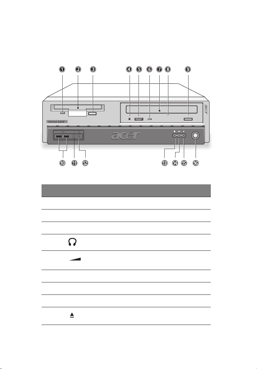
Front panel
Your computer’s front panel consists of the following:
Label Icon Component
2 System tour
1 Floppy drive light-emitting diode (LED)
2 3.5-inch floppy drive
3 Floppy drive eject button
4 CD/DVD Headphone/Earphone port
5 Volume control tuner
6 CD/DVD LED
7 CD/DVD tray
8 CD/DVD emergency eject slot
9 Stop/Eject button
Page 21
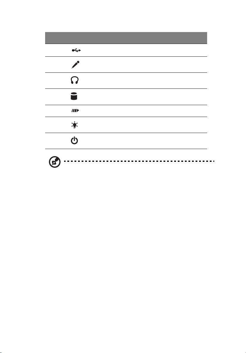
Label Icon Component
10 USB ports
11
11
Microphone-in port (front)
see note
12 Headphone-out port
13 Hard disk activity LED
14 LAN activity LED
15 Power LED
16 Power switch
Note: The system has two microphone-in ports (front and rear).
However, you can not use both of them at the same time. The
default setting for your system enables the microphone-in port in
front and disables the one at the back.
Page 22
12
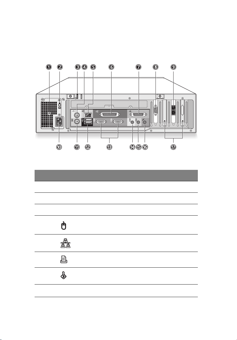
Rear panel
Your computer’s rear panel consists of the following:
Label Icon Color Component
2 System tour
1 Power supply
2 Voltage selector switch
3Keyhole
4 Green PS/2 mouse port
5 Gray Network port
6 Burgundy Parallel/Printer port
7 Gold Game/MIDI port
8
VGA port (add-on card)
see note
Page 23
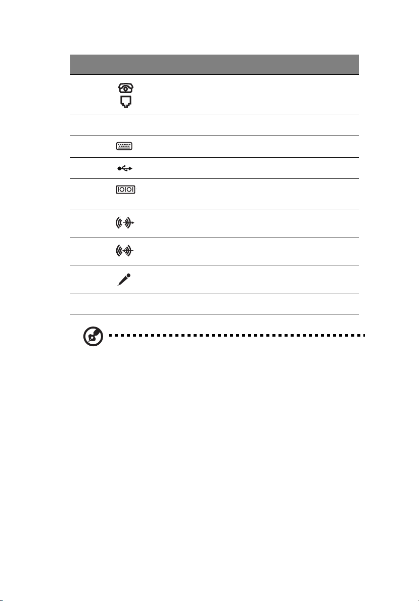
Label Icon Color Component
9 Black Handset/telephone line ports
(optional)
10 Power cord socket
11 Purple PS/2 keyboard port
12 Black USB ports
13
13 Teal or
Tur quoi se
14 Lime Audio-out/Line-out jack
15 Light blue Audio-in/Line-in jack
16 Pink Microphone-in port (rear)
17 Expansion slots
Note: The CRT monitor port is automatically disabled when an
add-on VGA card is installed into the system. Connect the monitor
to the VGA port instead.
Serial port
For information on how to connect the peripherals, see “Connecting
peripherals” on page 29 and “Connecting options” on page 35.
Page 24
14
2 System tour
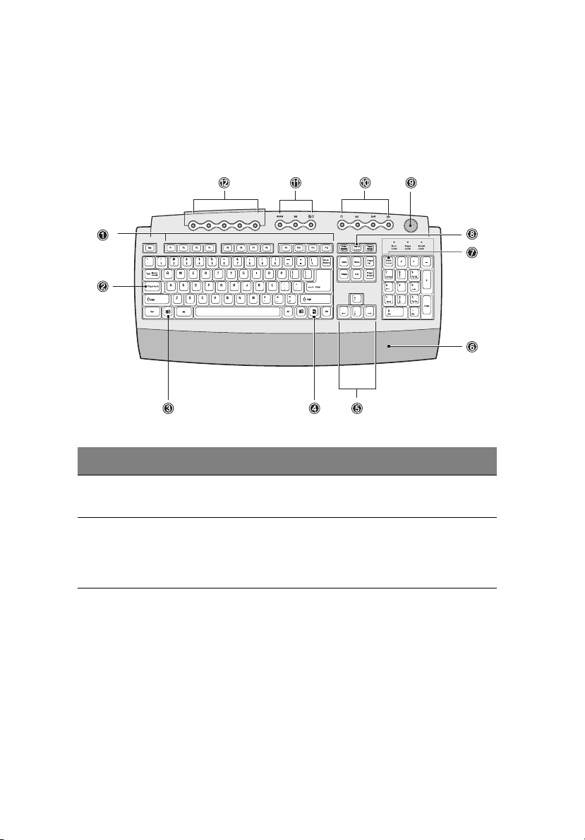
Keyboard
The keyboard that came with your computer has full-sized keys that
include separate cursor keys, two Windows keys, and twelve function
keys.
Item Component Description
1 Function keys Perform specific functions, depending
on the application that uses them.
2 Caps lock When activated, all alphabetic
characters typed appear in uppercase
(same function as pressing Shift +
<letter>).
Page 25
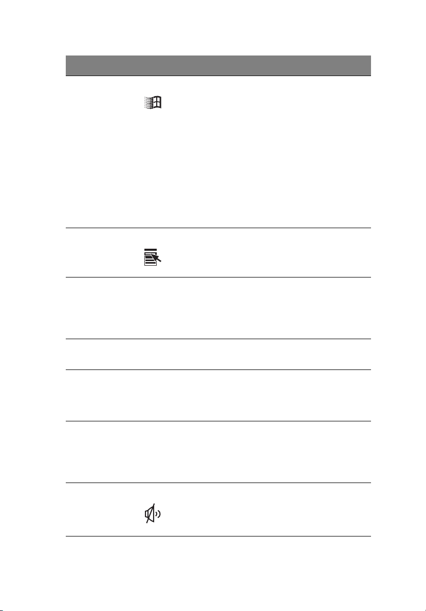
Item Component Description
3 Windows logo key Start button. Combinations with this
key perform special functions, such as:
• Windows + Tab: Activate the next
Taskbar button
• Windows + E: Explore My
Computer
• Windows + F: Find Document
• Windows + M: Minimize All
• Shift + Windows + M: Undo
Minimize All
• Windows + R: Display Run dialog
box
4 Application key Opens the applications context menu
(same function as clicking the right
button of the mouse).
5 Cursor keys Also called arrow keys, let you move the
cursor around the screen. They serve the
same function as the arrow keys on the
numeric pad when the Num lock is
toggled off.
15
6 Palm rest (detachable) Provides a comfortable place to rest your
hands while typing.
7 Num lock When activated, the keypad is set to
numeric mode, i.e., the keys function as
a calculator (complete with arithmetic
operators such as +, -, * and /).
8 Scroll lock When activated, the screen moves one
line up or down when you press the up
arrow or down arrow respectively. Take
note that Scroll Lock may not work with
some applications.
9 Volume control/Mute Controls the speaker volume. Turn it
clockwise or counterclockwise to adjust
the volume. Press it to toggle between
mute and sound.
Page 26
16
Item Component Description
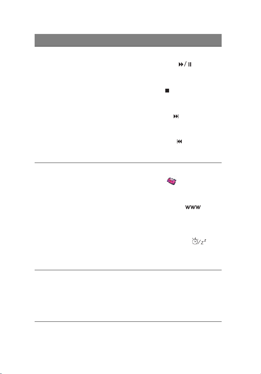
10 Multimedia keys Allow you to do the following:
• Play/Pause button : press to
start playing the audio track or
video file. Press again to pause.
• Stop button : press to stop
playing the audio track or video
file.
• Forward button : press to skip
forward to the next track or video
file and start playing.
• Backward button : press to skip
backward to the previous track or
video file and start playing.
11 Internet/Suspend keys Consist of three buttons:
• Email button : launches the
email application that came
bundled with your system.
2 System tour
• Web browser button :
launches the browser application
that came bundled with your
system.
• Suspend/Resume button :
puts the system to sleep when
pressed. To wake up the system
press it again.
12 Programmable keys Help you directly access a URL (Web site)
or launch any program, file, or
application in your system. The fifth key
is set to launch the media player.
To configure the settings of each key,
right-click on the Magic Keyboard icon
located on the Windows taskbar.
Page 27
17
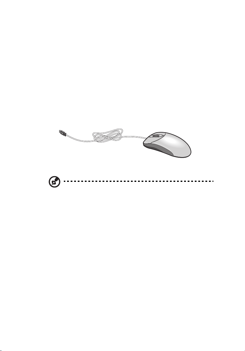
Mouse
The mouse has one ratchet wheel and two buttons: a left button and a
right button. Quickly pressing and releasing the buttons is called
clicking. Sometimes, you will need to do a double-click (clicking the
same button twice quickly) or a right-click (clicking the right button
quickly).
The ratchet wheel in between the two buttons is added to provide
easier scrolling capability. By simply moving the wheel with your index
finger, you can quickly move through multiple pages, lines, or
windows. The wheel may also function as a third button allowing you
to quickly click or double-click an icon or a selected item.
Note: If you are left-handed, refer to your Windows manual for
instructions on how to set up your mouse for left-handed use.
Page 28
18
2 System tour
Disk drives
Your computer comes with the following disk drives:
Floppy drive
Your computer’s 3.5-inch floppy drive can handle 720-KB and 1.44-MB
capacity diskettes.
The floppy diskettes are compact, lightweight, and easy to carry
around. Here are some tips on how to take care of your diskettes:
• Always make backup copies of the diskettes that contain
important data or program files.
• Keep diskettes away from magnetic fields and sources of heat.
• Avoid removing a diskette from a drive when the floppy drive
activity light is on.
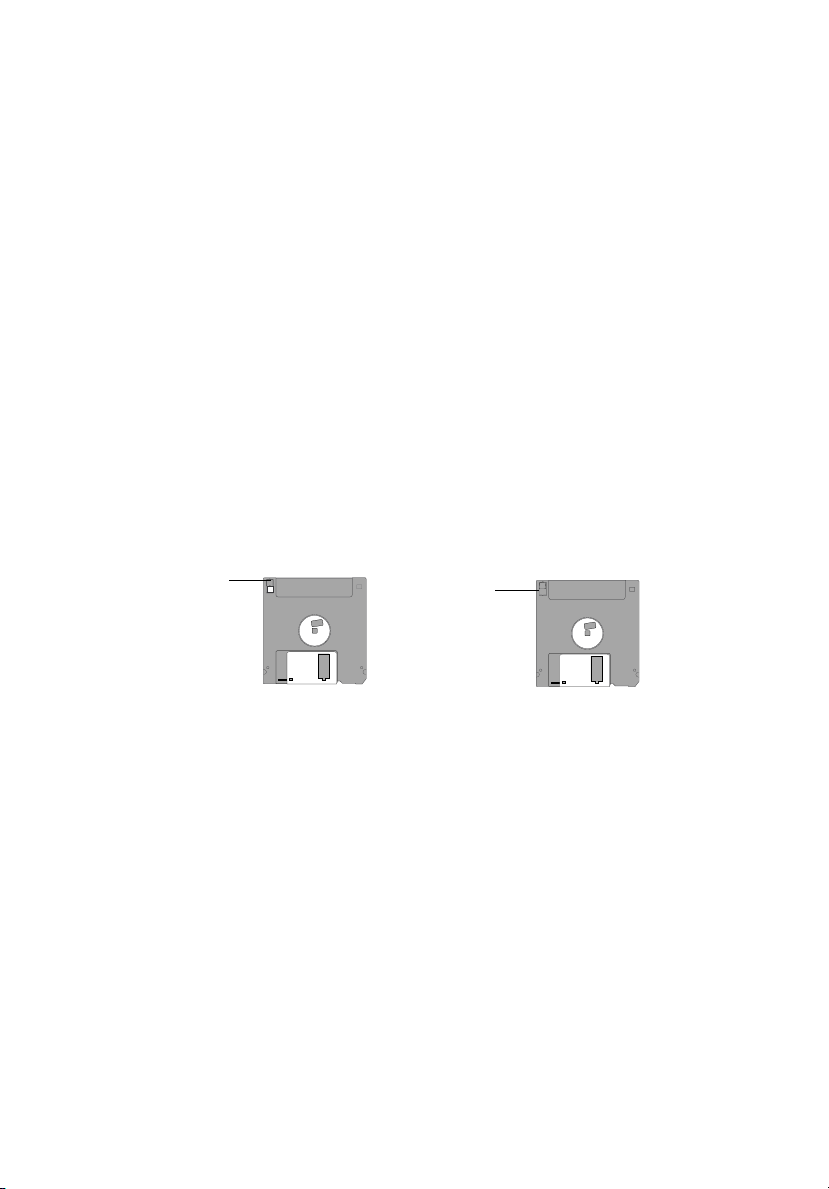
• Write-protect your diskettes to prevent accidental erasure. To do
this, slide the write-protect tab to the write-protect position.
Write-protected
• When you put a label on a 3.5-inch diskette, make sure that the
label is properly attached (flat on the surface) and within the
labeling area (area with a slight surface depression) on the
diskette. An improperly attached label may cause a diskette to get
stuck in a drive when you are inserting or removing it.
Not
write-protected
Page 29
19
CD-ROM/DVD-ROM/CD-RW drive
Your computer may come with a CD-ROM, DVD-ROM or a CD-RW
drive. This drive is located on the front panel of your computer. The
CD-ROM drive allows you to play different types of compact discs (CDs).
The DVD-ROM drive allows you to play not only old CD-ROMs, CD-I
discs, and video CDs, but new digital video discs (DVDs) as well. The
CD-RW drive allows you to record or burn CD-RW (recordable or
rewritable) discs. DVD or DVD-ROM is a new type of disc media that
holds a minimum of 4.7-GB (gigabytes), enough for a full-length
movie. It is believed that it will eventually replace CD-ROMs, as well as
VHS video cassettes and laser discs.
CDs and DVDs, like diskettes, are also compact, lightweight, and easy
to carry around. However, they are more delicate than diskettes and
must be handled with extra care.
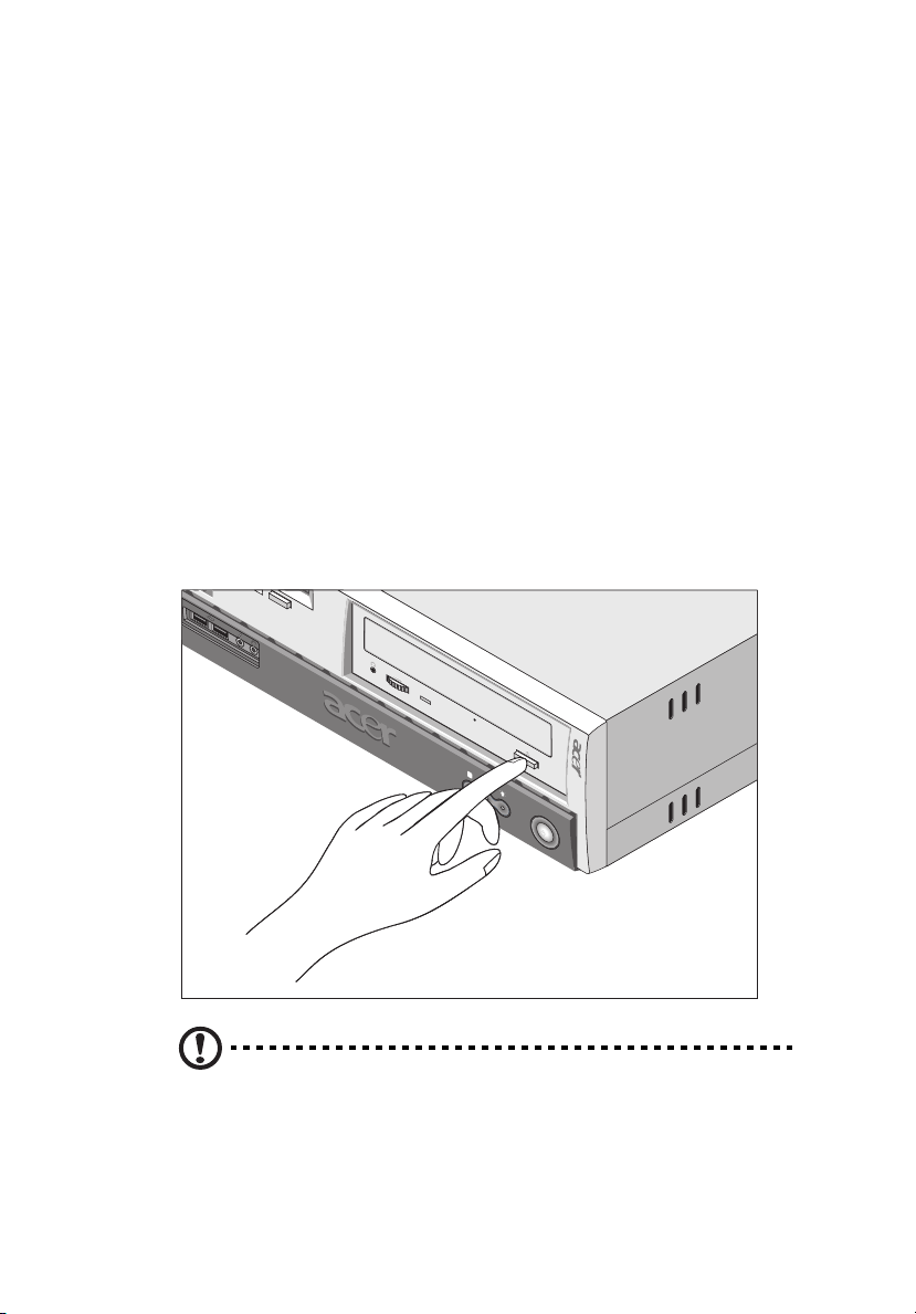
To insert a CD or DVD into your computer’s CD or DVD drive:
1. Gently push the eject button located on the front panel.
Caution! Avoid using low quality CDs, CD-Rs and CD-RWs,
because they could be damaged by your computer’s CD or DVD
drive.
Page 30
20
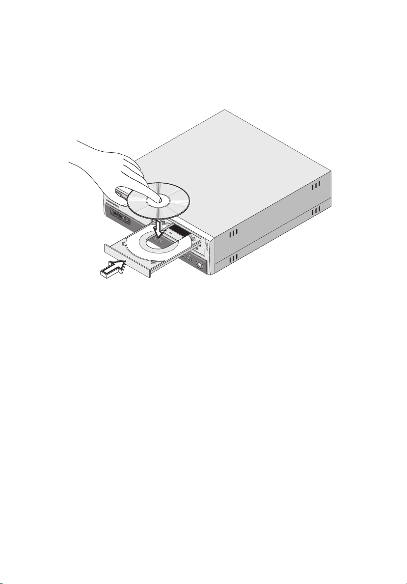
2. When the disc tray slides open, insert the CD or DVD. Make sure
that the label or title side of the disc is facing upward. When
holding a disc, hold it by the edges to avoid leaving smudges or
fingerprints.
3. Push the eject button again to close the tray.
2 System tour
To take care of your CDs and DVDs:
• Keep your discs in a disk case when not in use to avoid scratches or
other damage. Any kind of dirt or damage can affect the data on
the disc, impair the disc lens reader on the CD or DVD drive, or
stop the computer from successfully reading the disc.
• When handling discs, always hold them by the edges to avoid
smudges or fingerprints.
• When cleaning discs, use a clean, dust-free cloth and wipe in a
straight line from the center to the edge. Do not wipe in a circular
motion.
• Clean your CD or DVD drive periodically. You may refer to the
Cleaning kit for instructions. Cleaning kits can be purchased in any
computer or electronics shop.
Page 31

Hard disk
Your computer is preinstalled with a high-capacity Enhanced-IDE (EIDE) hard disk. If you want to replace your hard disk or upgrade it,
contact your dealer or a qualified service technician for assistance.
21
Page 32

22
2 System tour
Page 33

3 Setting up your
computer
Page 34

This chapter contains step-by-step
instructions on how to set up your computer
and connect additional peripherals.
Page 35

25
Arranging a comfortable work area
Working safely begins with the arrangement of your work space and
the proper use of equipment. For this reason, it is very important to
take time and think about how you are going to arrange your work
area.
Here are some points to consider:
Adjusting your chair
Having the right kind of chair does not necessarily mean that you’ll be
properly supported. It is necessary to adjust your chair to fit your body.
Proper body posture will make you more comfortable and productive.
• Avoid tilting your chair. If you have a chair that tilts, lock the tilt
knobs so that your chair will not tilt forward or backward while
you are using your computer.
• Adjust your chair height in such a way that you can sit on it with
your thighs parallel to the floor and your feet resting flat on the
floor.
• Rest your body on the chair back. Your torso works harder to
maintain balance if you do not rest your body on the chair back.
Positioning your Veriton PC
You may position your computer in two ways:
• Tower-like/vertical position
• Regular desktop position
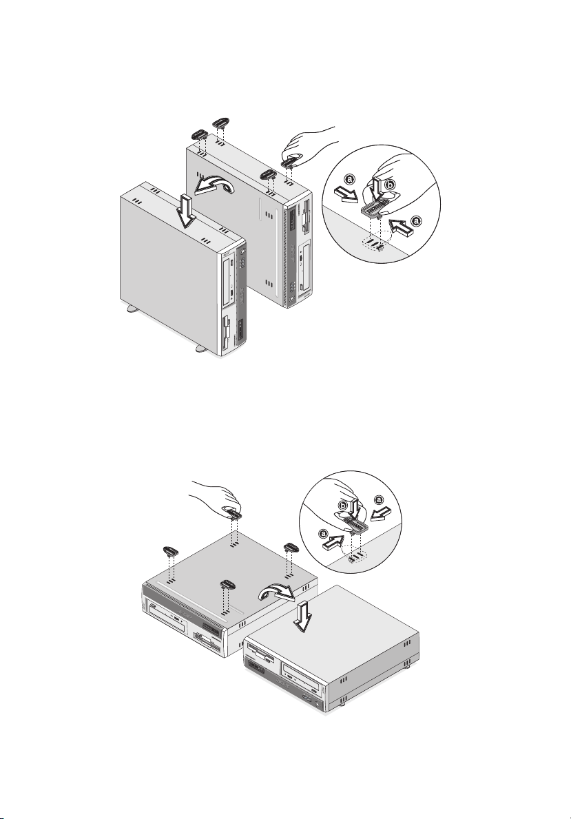
To position your PC in the tower-like or vertical
position:
1. Check the foot stands that came with your computer.
2. Install the foot stands.
a. Press the notch on both sides of the foot stands.
Page 36
26
b. Attach the foot stands to the slots on the housing frame as
shown in the figure below:
3 Setting up your computer
To place your PC in the regular desktop position:
1. Check the foot stands that came with your computer.
2. Attach the foot stands as shown in the figure that follows.
Page 37

27
3. Place your computer in the desired location.
Take note of the following when selecting a location for your
computer:
• Do not put your computer near any equipment that might cause
electromagnetic or radio frequency interference such as radio
transmitters, televisions, copy machines, or heating and airconditioning equipment.
• Avoid dusty areas and extremes of temperature and humidity.
• You may place your computer beside your desk or under your
table, as long as it does not block the space that you need for
working and moving.
Positioning your monitor
Place your monitor at a comfortable viewing distance, usually 50 to 60
centimeters away. Adjust the display in such a way that the top of the
screen is at or slightly below eye level.
Positioning your keyboard
The location of the keyboard is a very important factor to your
posture. Placing it too far away will make your body lean forward
forcing you to sit in an unnatural position. Placing it too high will add
tension to your shoulder muscles.
• The keyboard should be placed just above your lap. Adjust the
keyboard height by flipping the folding stands located under the
keyboard.
• Keep your lower arms parallel to the floor as you type. Your upper
arms and shoulders should be relaxed. Then try typing with a light
touch. If you feel any shoulder or neck strain, stop for a while and
check your posture.
• Position your keyboard in front of your monitor. Putting your
keyboard beside your monitor will make you turn your head while
you type which could add tension to your neck muscles that may
later result in neck strain.
Page 38

28
3 Setting up your computer
Positioning your mouse
• The mouse should be placed on the same surface as your keyboard
so that you can reach it with ease.
• Adjust its position to allow enough space for movement without
making you stretch or lean over.
• Use your arm to move the mouse. Do not rest your wrist on the
table when moving the mouse.
Page 39
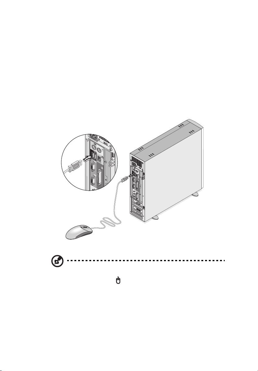
Connecting peripherals
Setting up your computer is easy. For the most part, you only have
four things to connect: the USB mouse, the USB keyboard, the
monitor, and the power cable.
USB mouse
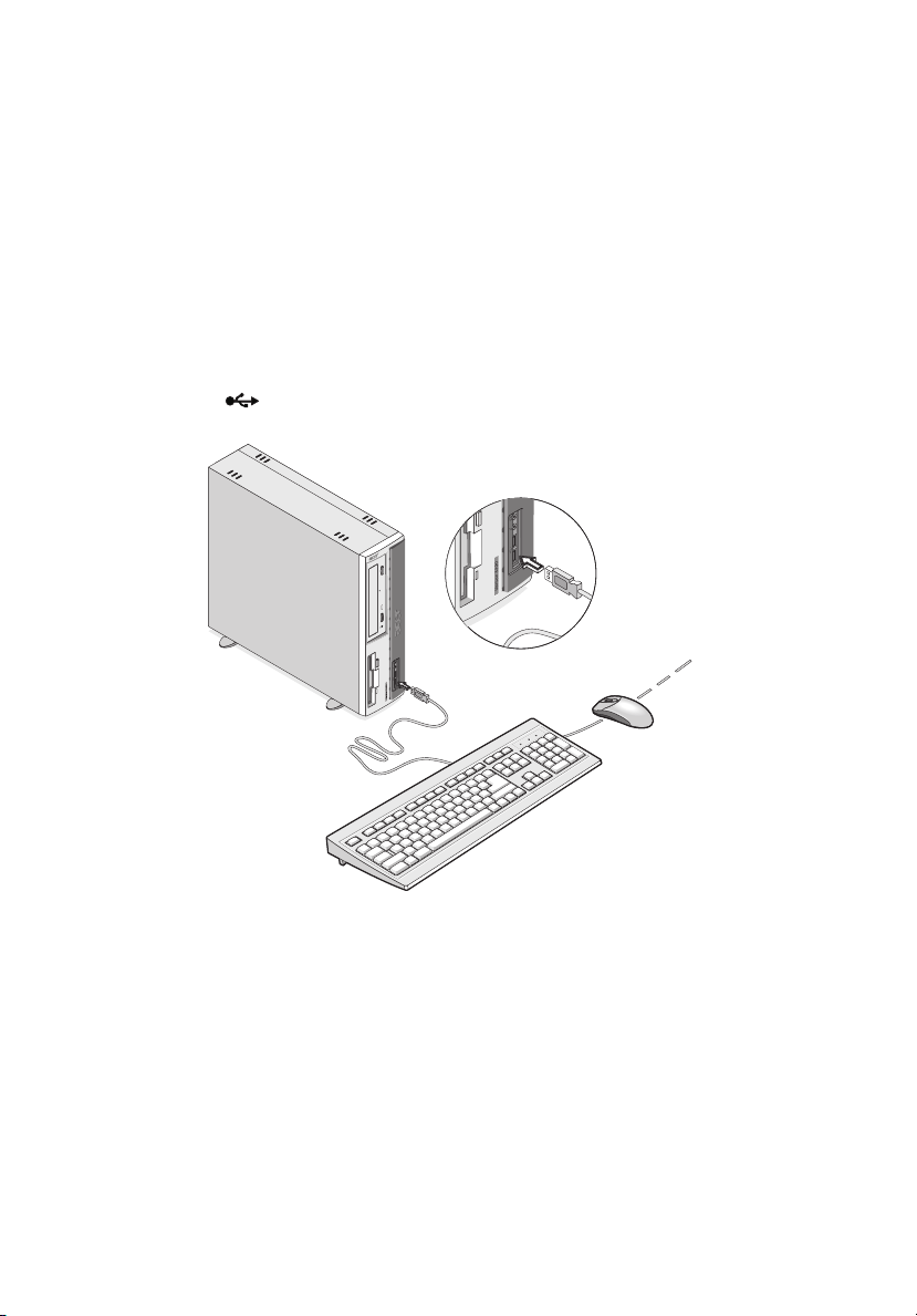
Plug the USB mouse cable into any of the USB ports located on the
front or rear panel of your computer.
29
Note: If you are using a PS/2 mouse, plug the mouse cable into
the PS/2 mouse port (green port) located on the rear panel of
your computer.
Page 40
30
3 Setting up your computer
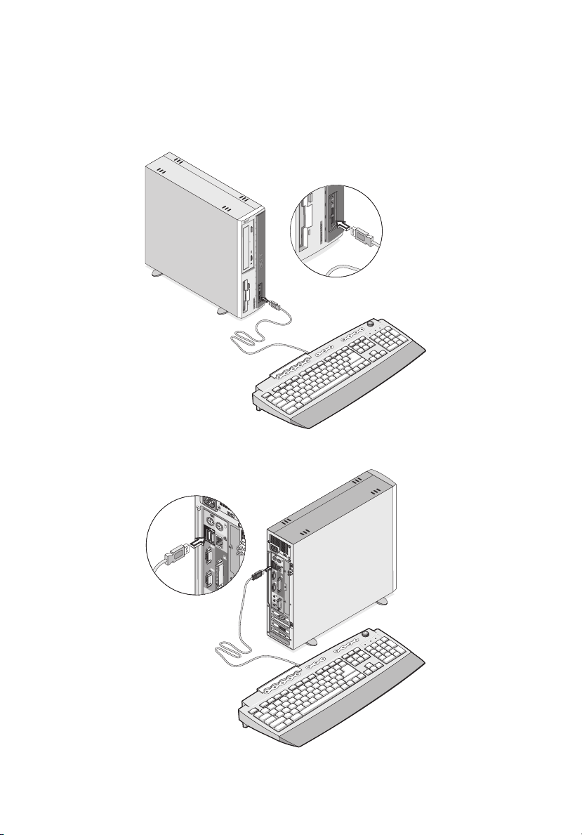
USB keyboard
Plug the USB keyboard cable into any of the USB port located on the
front or rear panel of your computer.
Page 41
31
Note: If you are using a PS/2 keyboard, plug the keyboard cable
into the PS/2 keyboard port (purple port) located on the rear
panel of your computer.
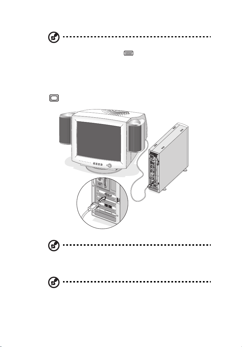
Monitor
To connect a monitor, simply plug the monitor cable into the monitor
port (blue port) located on the rear panel of your computer.
Note: The CRT monitor port is automatically disabled when an
add-on VGA card is installed into the system. Connect the monitor
to the VGA port instead.
Note: Refer to the monitor manual for additonal instructions and
information.
Page 42
32
3 Setting up your computer
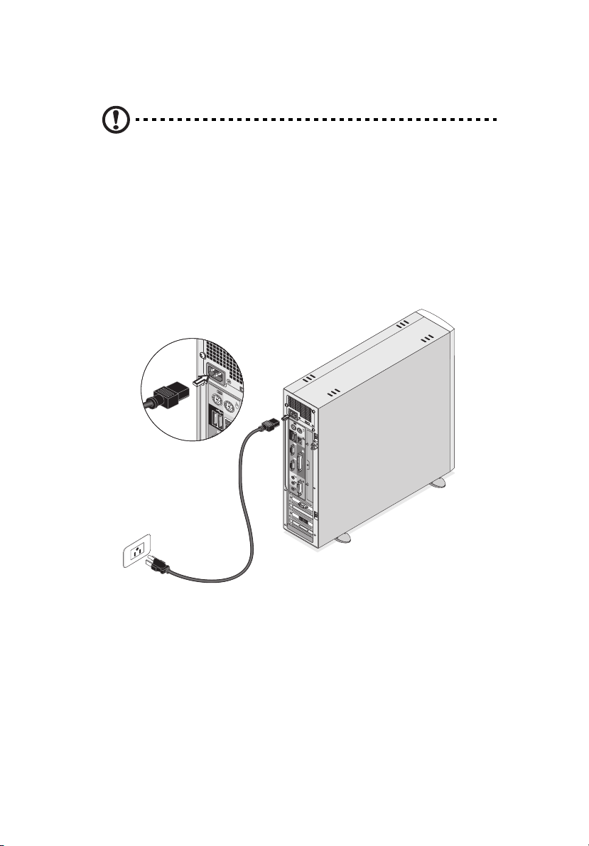
Power cable
Caution! Before you proceed, check the voltage range in your
area. Make sure that it matches your computer’s voltage setting
(refer to page 12 for the location of the voltage selector switch on
the rear panel of your computer). If they don’t match, change
your computer’s voltage setting according to your area’s voltage
range.
Plug the power cable into the power cable socket located on the rear
panel of your computer. Then plug the other end of the power cable
into a power outlet.
Page 43
33
Turning on your computer
After connecting the necessary peripherals and plugging in the power
cable, you are now ready to turn the computer on and get to work.
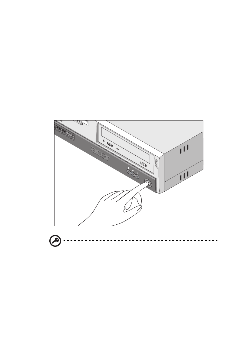
To turn on your computer:
1. Turn on all peripherals connected to your computer such as the
monitor, printer, fax, speakers, etc.
2. On the rear panel of your computer, set the voltage selector switch
to the voltage range applicable to your area.
3. On the front panel of your computer, press the power button.
Important: Make sure that the power cable is properly plugged
into an electrical outlet. If you are using a power strip or an AVR
(Auto-Voltage Regulator), make sure that it is plugged in and
turned on.
Page 44

34
3 Setting up your computer
Turning off your computer
To turn off your computer, click on the Start button, highlight Shut
Down, select Shut down; then click on OK. You can then turn off all
peripherals connected to your computer.
If you cannot shut down your computer normally, press the power
button for at least four seconds. Quickly pressing the button may put
the computer in Suspend mode only.
Page 45
Connecting options
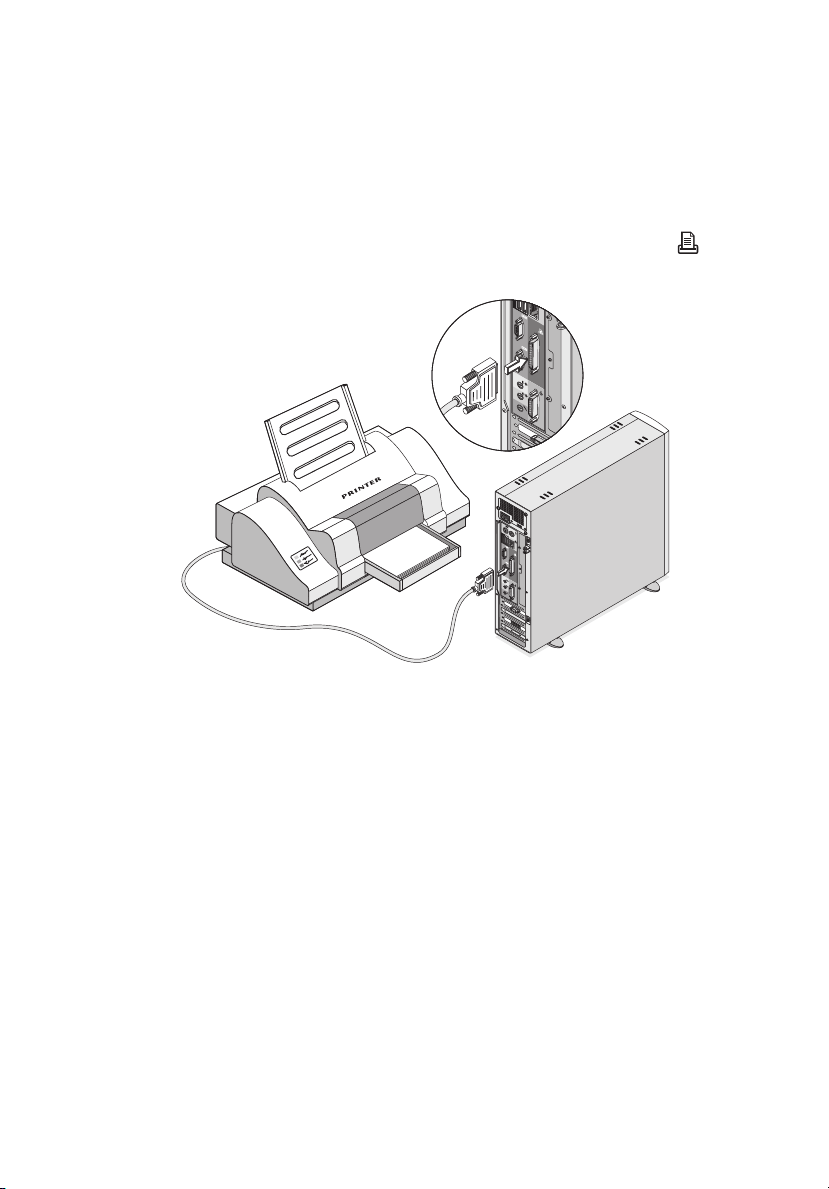
Printer
To connect a printer, plug the printer cable into the parallel port
(burgundy port) located on the rear panel of your computer.
35
Page 46
36
3 Setting up your computer
Serial Mouse
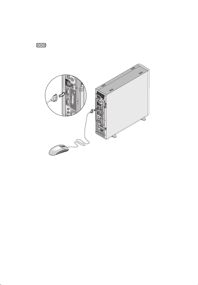
To connect a serial mouse, plug the serial mouse cable into the serial
port (teal or turquoise port) located on the rear panel of your
computer.
Page 47
37
LCD Monitor
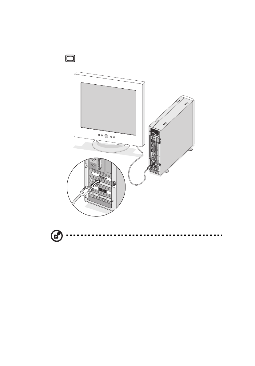
To connect an LCD monitor, plug the LCD monitor's VGA cable into the
VGA port (blue port) located on the rear panel of your computer.
Note: Refer to the LCD monitor manual for additonal instructions
and information.
Page 48
38
3 Setting up your computer
Network
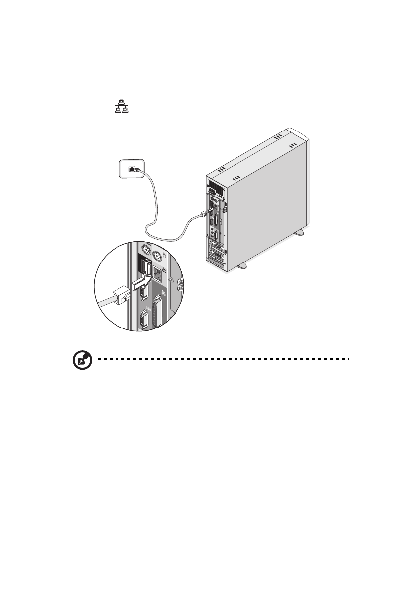
You can connect your computer to a Local Area Network (LAN) using a
network cable. To do so, simply plug the network cable into the
network port (gray port) on the rear panel of your computer.
Note: Consult your operating system manual for information on
how to configure your network setup.
Page 49
Modem (optional)
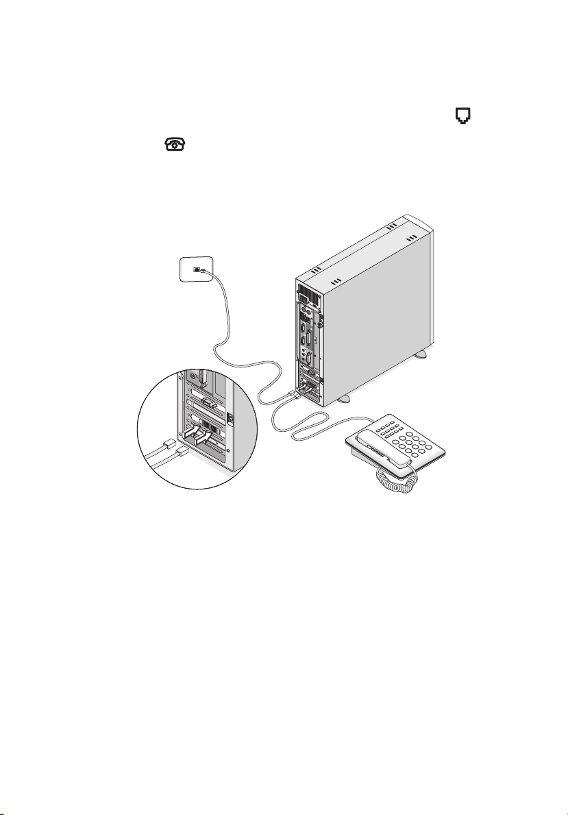
Set up your modem connection by plugging the telephone line
and handset into their corresponding ports on the rear panel of
your computer.
Refer to the figure below for the connections.
39
Page 50
40
3 Setting up your computer
Multimedia devices
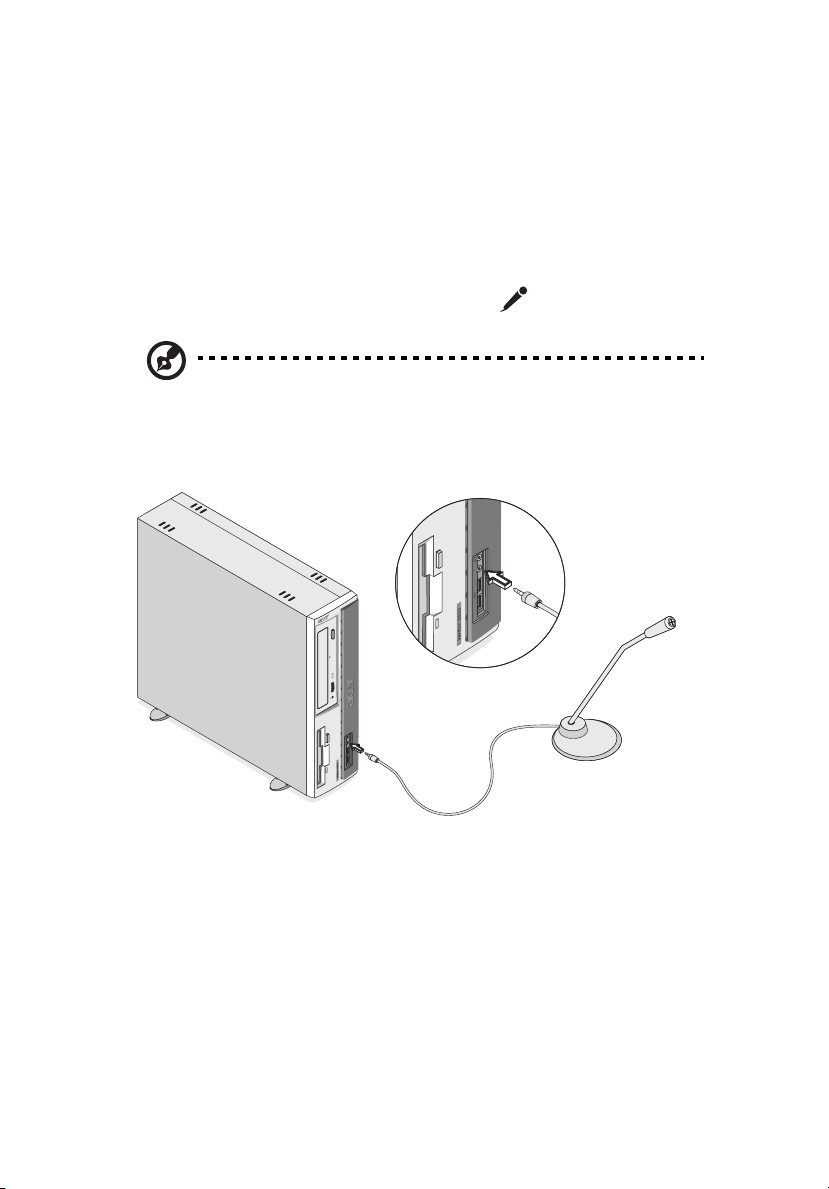
You can connect multimedia devices such as a microphone,
headphones or earphones, external speakers, audio line-in device and
a joystick (for games). These devices will allow you to take advantage
of your computer’s multimedia features.
Plug the devices in as follows:
• microphone: connects to the Mic-in port (pink port) located
on the front and rear panel of your computer
Note: The system has two microphone-in ports (front and rear).
However, you can not use both of them at the same time. The
default setting for your system enables the microphone-in port in
front and disables the one at the back.
Page 51
41
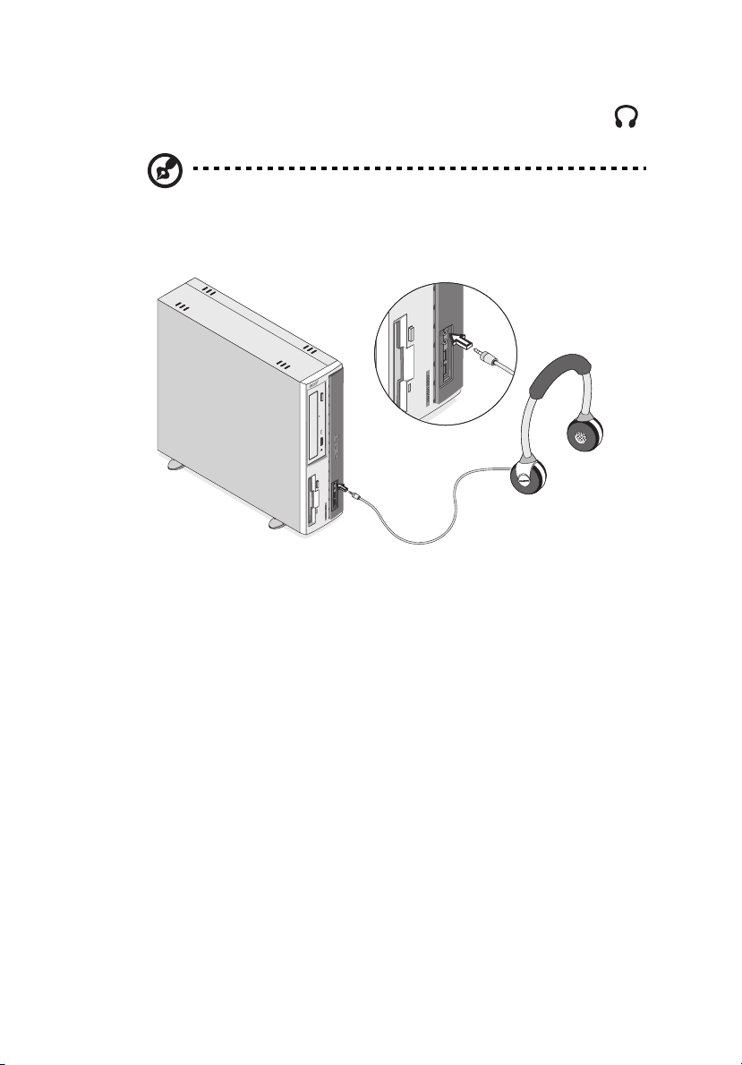
• earphones, headphones: connect to the Headphone-out port
(lime port) located on the front panel of your computer
Note: To adjust the volume of the headphones, click on the
Volume icon located on the taskbar at the bottom of your screen.
When the volume control pops up, drag the volume control lever
to the desired level.
Page 52
42
3 Setting up your computer
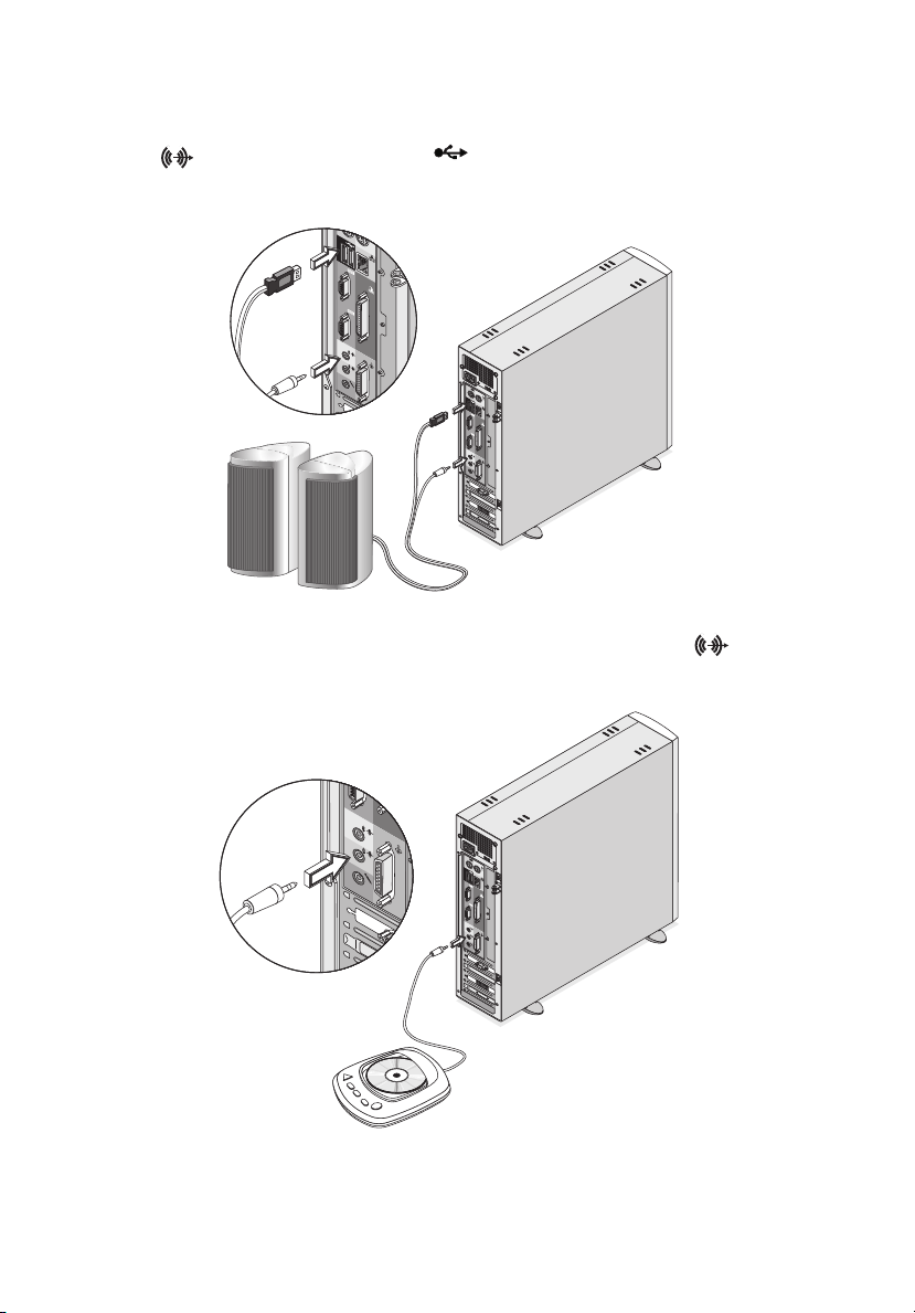
• external USB speakers: connect to the Audio-out/Line-out jack
(lime jack) and USB port (black port) located on the rear
panel of your computer
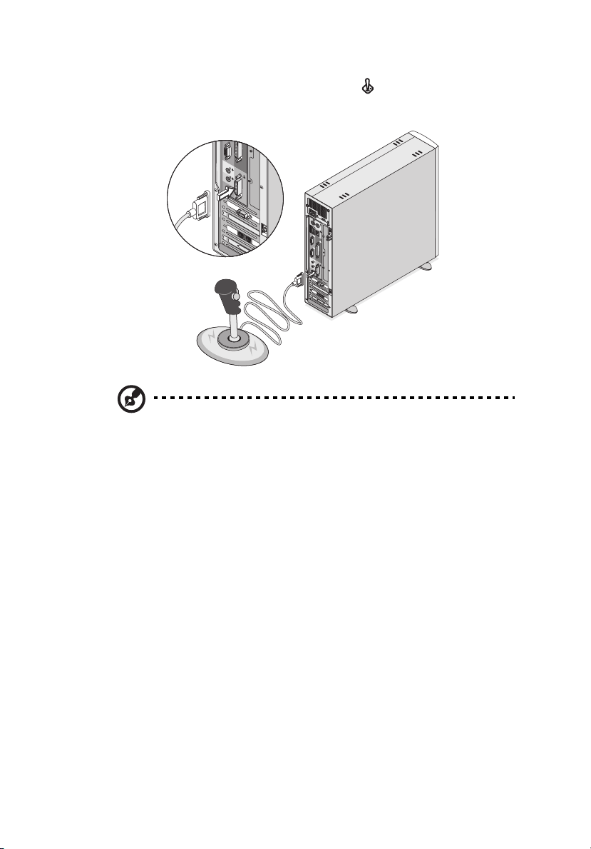
• audio line-in device: connect to the Audio-in/Line-in jack
(light blue jack) located on the rear panel of your computer
Page 53
43
• joystick: connect to the Game/MIDI port (gold port) located on
the rear panel of your computer
Note: For information on how to configure multimedia devices,
consult the documentation that came with each device.
Page 54
44
3 Setting up your computer
USB devices
Universal Serial Bus (USB) is a newer serial bus design that is capable of
cascading low-/medium-speed peripherals (less than 12 Mbps) such as a
keyboard, mouse, speakers, joystick, scanner, printer and modem.
With USB, complex cable connections can be eliminated.
Your computer comes with four USB ports: two each on both the front
and rear panels. These ports allow you to connect additional devices
to your computer without using up precious system resources.
To connect a USB device, simply plug the device cable into any of the
USB ports (black port).
Page 55
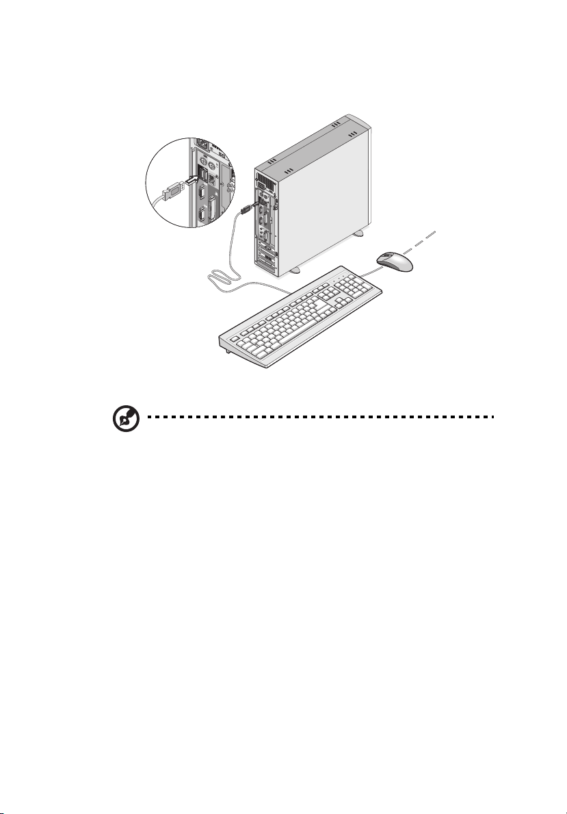
Note: Most USB devices have a built-in USB port which allows you
to connect or daisy-chain more USB devices.
45
Page 56

46
3 Setting up your computer
Page 57

4 Upgrading your
computer
Page 58

This chapter contains instructions on how to
upgrade your computer and basic
information about your system boards that
you will find helpful when performing the
upgrade process.
Page 59

Installation precautions
Before you install any computer component, we recommend that you
read the following sections. These sections contain important ESD
precautions along with preinstallation and post-installation
instructions.
ESD precautions
Electrostatic discharge (ESD) can damage your processor, disk drives,
expansion boards, and other components. Always observe the
following precautions before you install a computer component:
1. Do not remove a component from its protective packaging until
you are ready to install it.
2. Wear a wrist grounding strap and attach it to a metal part of the
computer before handling components. If a wrist strap is not
available, maintain contact with the computer throughout any
procedure requiring ESD protection.
Preinstallation instructions
Always observe the following before you install any component:
1. Turn off your computer and all the peripherals connected to it
before opening it. Then unplug all cables from the power outlets.
2. Open your computer according to the instructions on page 51.
3. Follow the ESD precautions described above before handling a
computer component.
4. Remove any expansion boards or peripherals that block access to
the DIMM sockets or component connector.
5. See the following sections for specific instructions on the
component you wish to install.
49
Warning! Not turning off the computer properly before
you start installing the components may cause serious
damage.
Do not attempt the procedures described in the following
sections unless you are a qualified service technician.
Page 60

50
4 Upgrading your computer
Post-installation instructions
Observe the following after installing a computer component:
1. See to it that the components are installed according to the stepby-step instructions in their respective sections.
2. Replace any expansion boards or peripherals that you removed
earlier.
3. Replace the top cover.
4. Connect the necessary cables and turn on your computer.
Page 61
51
Opening your computer
Caution: Before you proceed, make sure that you have turned
off your computer and all peripherals connected to it. Read the
“Preinstallation instructions” on page 49.
You need to open your computer before you can install additional
components. See the following section for instructions.
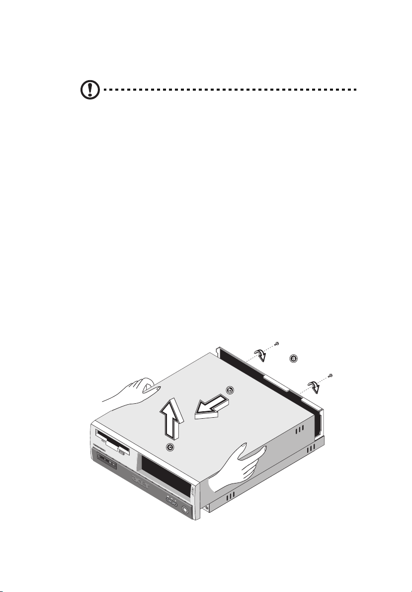
To remove the top cover
1. Turn off your computer and unplug all cables.
2. Place your computer on a flat, steady surface. If your computer is
in the vertical position, remove the foot stands and place your
computer in the regular desktop position.
3. Remove the top cover.
(a) Remove the two screws from the rear panel using a screwdriver
and set the screws aside.
(b) Hold the sides of the cover with both hands.
(c) Slide it back about an inch and then gently lift it upward to
detach it.
Page 62
52
4 Upgrading your computer
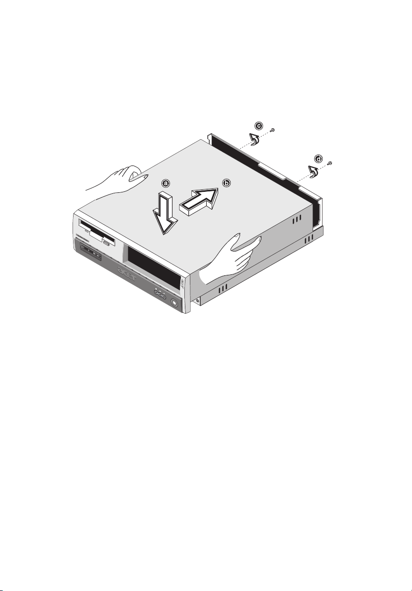
To replace the top cover
1. Align the cover’s hinges to the housing frame (a); then gently push
it in to slide it back into place (b).
2. Secure the cover with two screws (c,d).
Page 63
Internal components
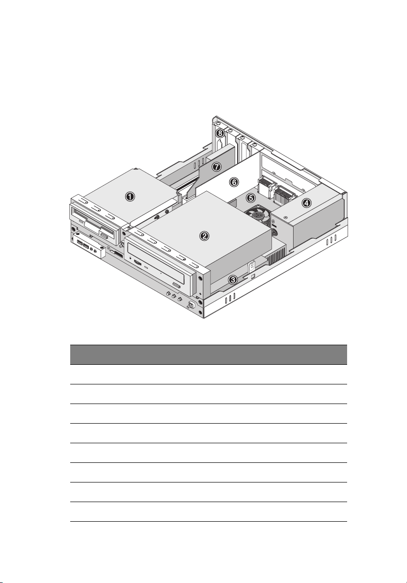
The figure below shows what your computer looks like once you
remove the cover:
53
Number Component
1 3.5-inch floppy drive
2 CD-ROM/DVD-ROM/CD-RW drive
3 Drive frame
4Power supply
5 Mainboard
6VGA card
7Modem card
8 Expansion slot
Page 64
54
4 Upgrading your computer
Replacing the hard disk
Follow these steps to replace your computer’s hard disk:
1. Remove the top cover (see page 51).
2. Detach all cables connected to the CD-ROM/DVD-ROM/CD-RW and
3.5-inch floppy drives.
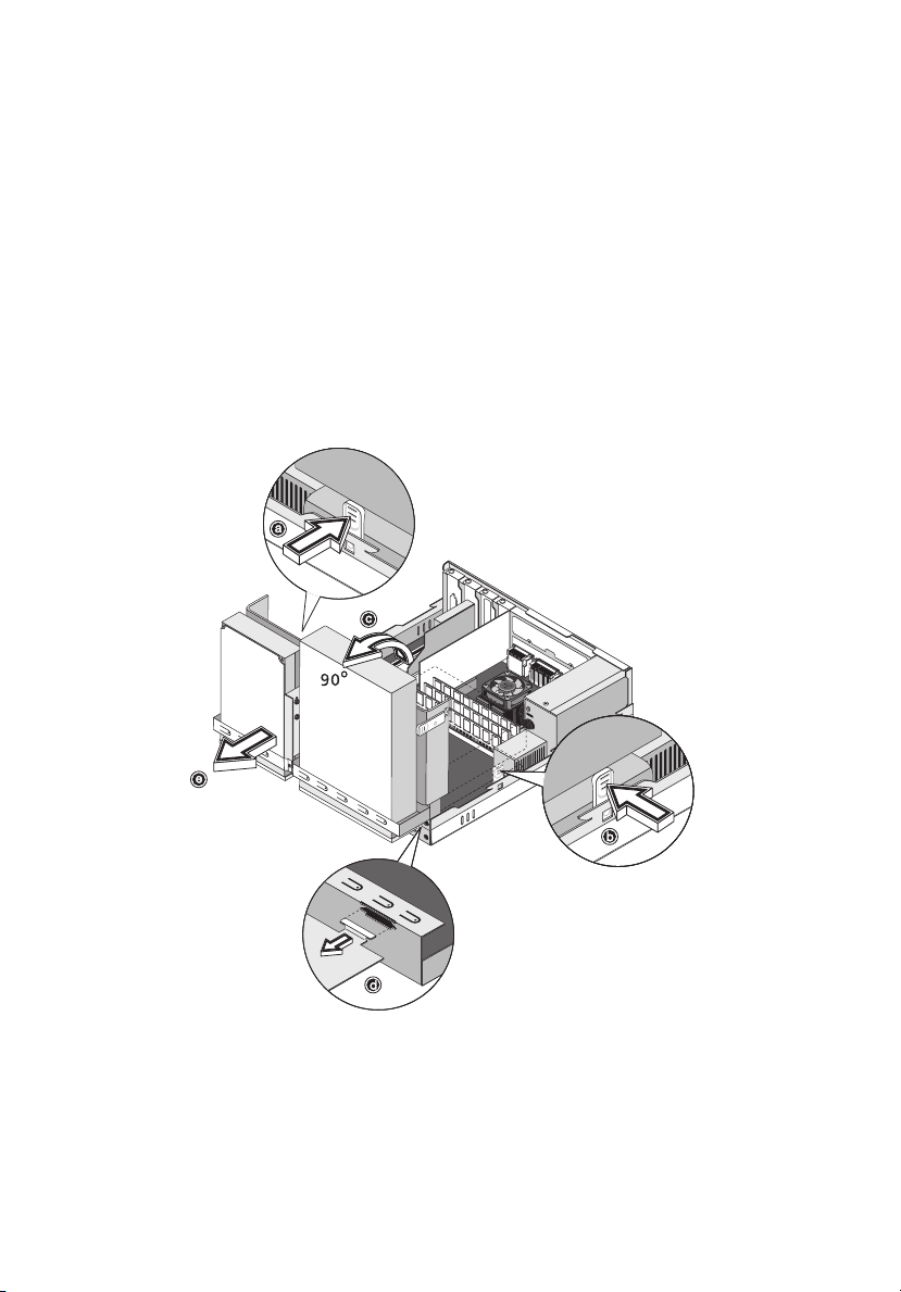
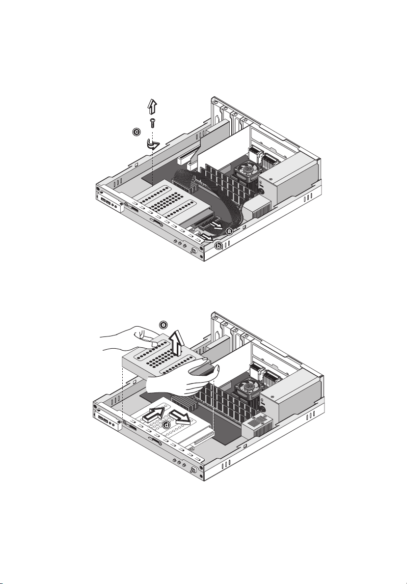
3. Press the tabs (a) and (b) on both sides of the drive frame to
release it from the housing.
Rotate the drive frame to a 90-degree angle (c); then pull out (d),
and remove the drive frame (e).
Page 65
55
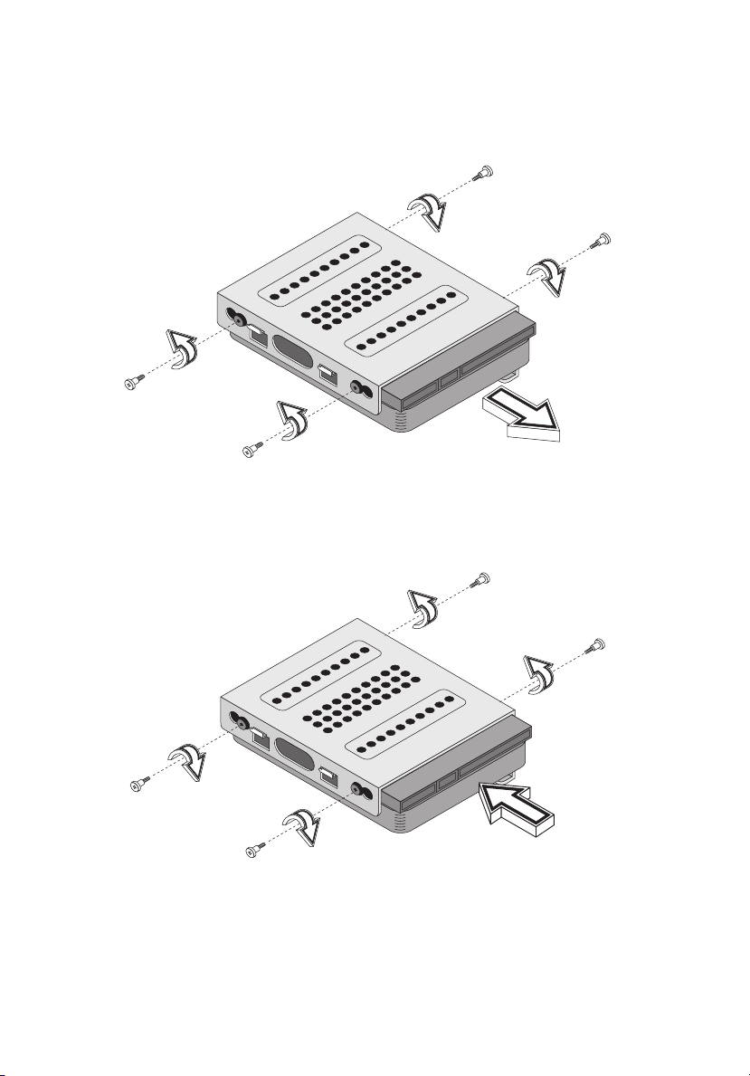
4. Detach hard disk cable (a) and power cable (b) from the hard disk.
Then, remove the screw that holds the hard disk to the housing (c).
Set the screw aside.
5. Slide the hard disk frame to the right (d); then gently move it
inward to detach it (e).
Page 66
56
4 Upgrading your computer
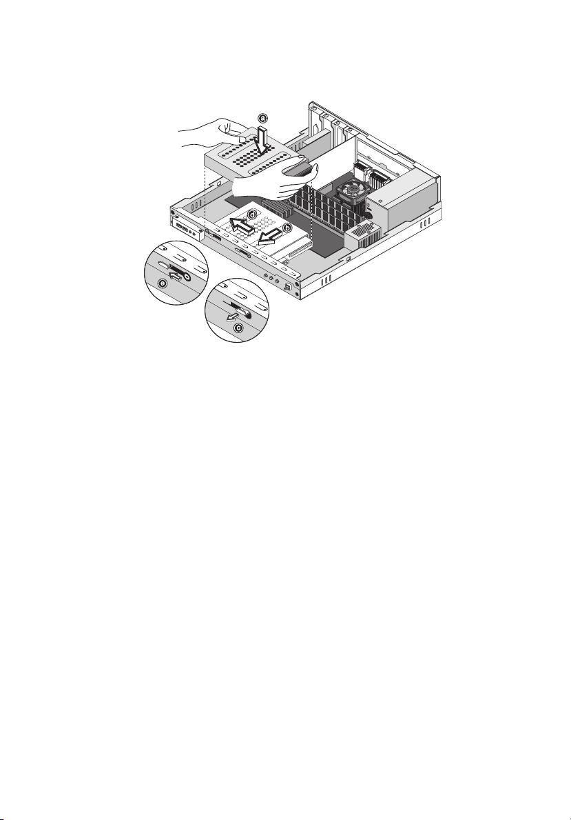
6. Remove the four screws that hold the hard disk to the hard disk
frame and detach the hard disk. Set the screws aside.
7. Insert the new hard disk into the hard disk frame and secure it
with the four screws.
Page 67
57
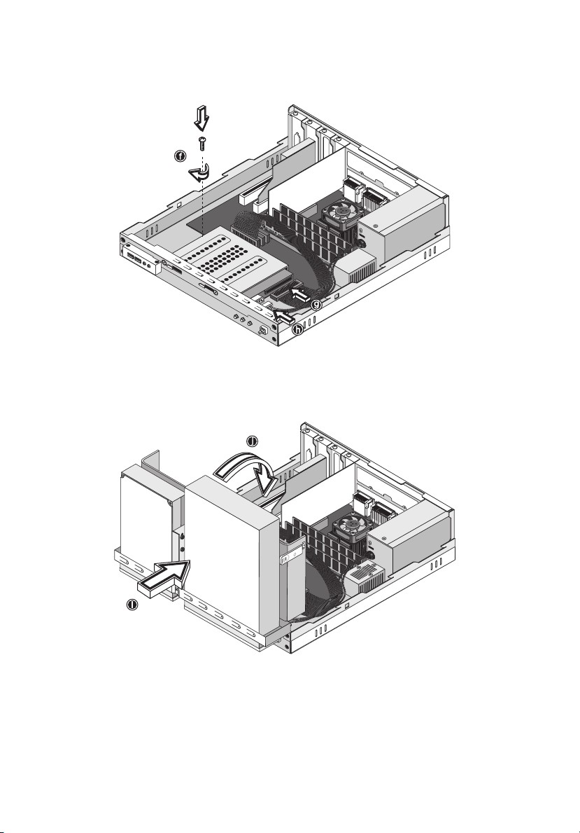
8. Reinstall the hard disk frame into the housing (see figures below).
Page 68
58
4 Upgrading your computer
9. Reinstall the drive frame into the housing (see figures below).
Make sure the tabs on both sides snap into place.
10. Reattach the CD or DVD drive and the floppy drive cables.
Page 69

Note: Make sure that the other ends of the disk drive cables are
securely connected to their corresponding connectors on the
mainboard.
11. Replace the top cover (see page 52).
59
Page 70
60
4 Upgrading your computer
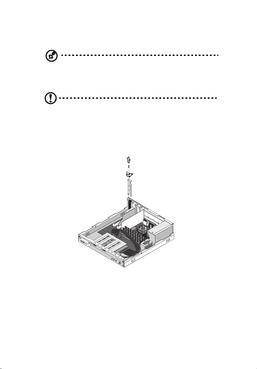
Installing an expansion card
Note: Observe the “Installation precautions” on page 49 when
installing or removing a computer component.
To install an expansion card:
Caution! The system accepts low profile PCI cards only.
1. Remove the top cover (see page 51).
2. Locate an empty PCI slot on the mainboard.
3. Remove the screw that holds the bracket to the computer. Save
the screw.
4. Pull out the bracket on the housing opposite the selected empty
slot.
5. Remove the expansion card from its protective packaging.
Page 71
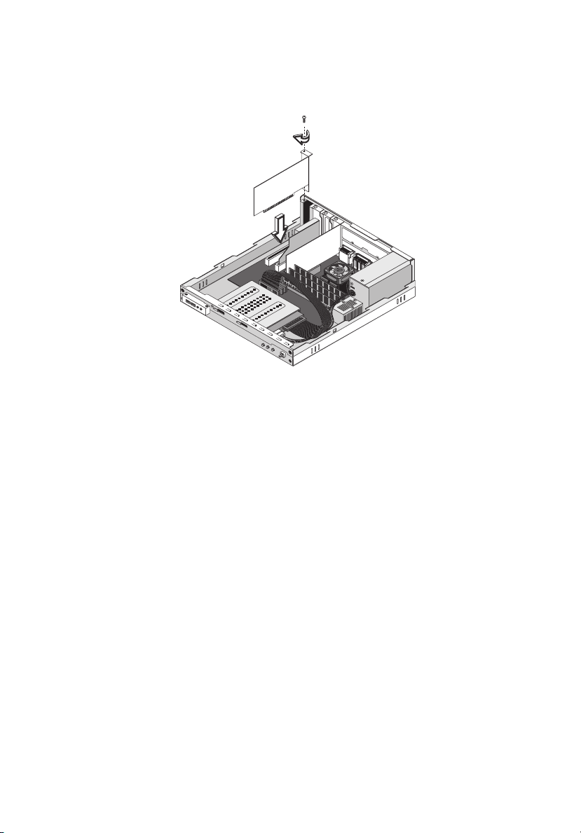
6. Align the card with the empty bracket and then insert it into the
slot. Make sure that the card is properly seated.
7. Secure the card to your computer with a screw.
8. Replace the top cover (see page 52).
When you turn on the computer, BIOS (Basic Input/Output System)
automatically detects and assigns resources to the newly-installed
devices.
61
Page 72
62
4 Upgrading your computer
System boards
Mainboard layout
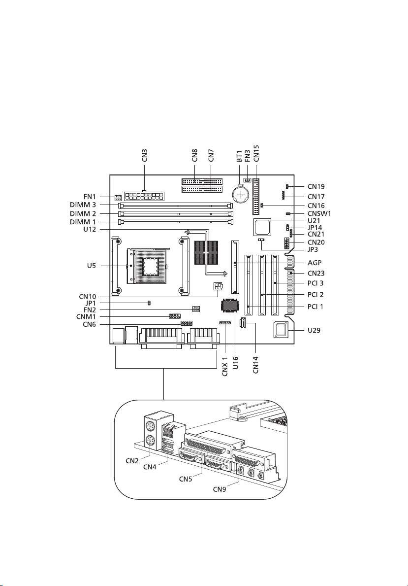
The mainboard becomes accessible once you open your computer. It
should look like the figure shown below:
Page 73
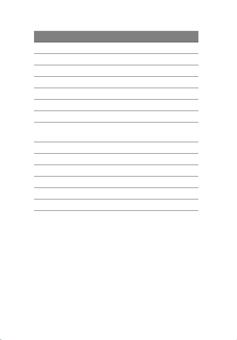
Label Component
AGP AGP slot
BT1 Battery
CN2 PS/2 mouse (upper) and keyboard (lower) ports
CN3 Power connector
CN4 Network (upper) and USB (lower) ports
CN5 Serial port (lower right and left) and parallel port (upper)
CN6 Memory stick connector
CN7 IDE 1 connector
CN8 IDE 2 connector
CN9 MIDI/game (upper), line-out (left), line-in (middle), and
rear mic-in (right) ports
CN10 Power connector (12 V power)
63
CN14 CD-in connector
CN15 FDD Connector
CN16 Intrusion connector
CN17 HDD LED connector
CN19 Power button
CN20 Front USB connector
CN21 Power/Suspend LED connector
CN23 EXT PCI slot
CNM1
SmartCard (COM 2) connector
CNSW1 IDE cold-swap connector
1
Page 74
64
Label Component
CNX1 Audio FPIO connector
DIMM 1-3 DIMM sockets 1-3
FN1 3-pin CPU fan connector
FN2 3-pin CPU fan connector
FN3 3-pin CPU fan connector
JP1 LAN active LED connector
JP3 Model select
JP14 1-2 Clear CMOS
2-3 Normal
PCI1 to 3 PCI slots 1 to 3
U5 CPU socket
U12 Intel 845 chipset
U16 SMSC chipset
2
4 Upgrading your computer
U21 Intel ICH2 chipset
U29 BIOS chipset
1 Share connection with serial port 2 (COM 2)
2 Default value
Page 75
Audio board
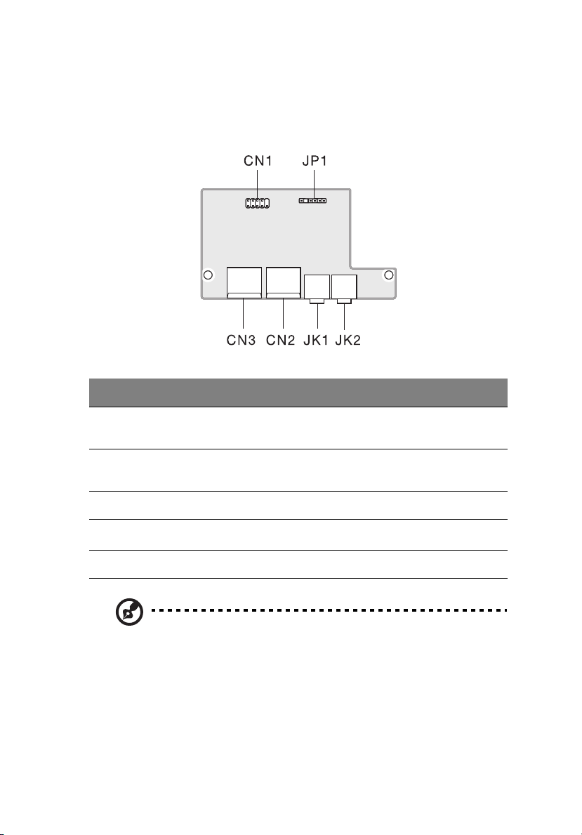
The audio board that came with your computer should look like the
figure that follows.
Label Description
JP1 Audio connector - connects to the AUDIO2 connector of
the mainboard
65
CN1 USB connector - connects to the USB2 connector of the
mainboard
CN2 and CN3 USB ports
JK1
JK2 Audio-out port
Note: The system has two microphone-in ports (front and rear).
However, you can not use both of them at the same time. The
default setting for your system enables the microphone-in port in
front and disables the one at the back.
Microphone-in port
see note
Page 76
66
4 Upgrading your computer
Installing additional memory
The three 168-pin sockets on the mainboard support Synchronous
Dynamic Random Access Memory (SDRAM)-type DIMMs. You may
install 32-MB, 64-MB, 128-MB, 256-MB, 512-MB or 1-GB single and
double density DIMMs for a maximum memory capacity of 3 GB.
The SDRAM DIMMs should work under 3.3 volts; 5-volt memory devices
are not supported. PC-100 (100MHz) and PC-133 (133 MHz) SDRAM are
supported. Contact your dealer for qualified DIMM vendors.
Caution! Do not install and use both PC-100 and PC-133 SDRAM
together. Such a combination might cause your computer to
malfunction.
Each of the DIMM sockets is independent from each other. This
independence allows you to install DIMMs with different capacities to
form different configurations.
To remove a DIMM
Note: Observe the “Installation precautions” on page 49 when
installing or removing a computer component. Also, make sure
that you have removed the top cover (see
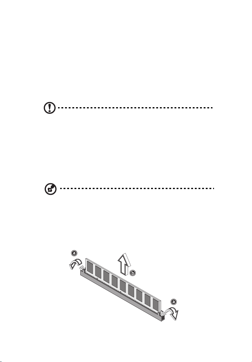
1. Press the holding clips on both sides of the DIMM socket outward
to release the DIMM (a).
2. Gently pull the DIMM out of the socket (b).
page 51).
Page 77
67
To install a DIMM
Note: Observe the “Installation precautions” on page 49 when
installing or removing a computer component. Also, make sure
that you have remove the top cover (see
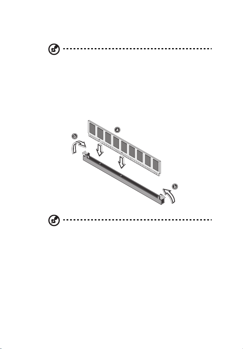
1. Open the clips on the socket.
2. Align the DIMM with the socket (a).
3. Press the DIMM into the socket until the clips lock onto the DIMM
(b).
page 51).
Note: The DIMM sockets are slotted to ensure proper installation.
If you insert a DIMM but it does not fit easily into the socket, you
may have inserted it incorrectly. Turn the DIMM around and try to
insert it again.
To reconfigure your computer
Your computer automatically detects the amount of memory installed.
Run the BIOS utility to view the new value for total system memory
and make a note of it. For more information on BIOS, refer to the
Veriton 3300 online guide (see “Accessing the online guide” on page
6).
Page 78

68
4 Upgrading your computer
Page 79

5 Software
Page 80

This chapter describes the applications that
came with your computer.
Page 81

Your computer comes with the following applications:
• Acrobat® Reader™
•LDCM
• Norton AntiVirus
• NTI CD-Maker 2000
•PowerDVD
• VariSpeed
• BIOS utility
All of the applications that came with your computer are very easy to
use. However, if you need more help and information, you may refer
to the online help documentation provided in each software
application.
71
Page 82

72
5 Software
Acrobat Reader
Acrobat Reader is a software that lets you view, navigate, browse and
print Adobe Portable Document Format (PDF) files on all major
computer platforms. Acrobat Reader can open your document across a
broad range of hardware and software, and it will look exactly as you
intended - with layout, fonts, links and images intact.
To run Acrobat Reader, double-click the Acrobat Reader icon on your
Windows's desktop.
For more information about Acrobat Reader, you may refer to its Help
menu.
Page 83
73
LDCM
LANDesk Client Manager (LDCM) allows desktop management via the
Web, standard network, or dial-up connections. It is compatible with
the leading management specifications, such as Wired for
Management 2.0, Desktop Management Interface (DMI) v2.0, and
others.
LDCM may not have been preloaded on your computer. As such, you
will need to install it. To do so, do the following:
1. Make sure that your computer is turned on.
2. Insert the Programs CD that came with your computer into the CD
or DVD drive.
3. Follow all onscreen instructions until you finish the installation.
Caution: Make sure that the CD is properly inserted into the CD
or DVD drive. Improper insertion may damage both the CD and
the CD or DVD drive. For instructions on how to insert a CD into
your computer's CD or DVD drive, click here.
Note: LDCM currently supports Windows Me and Windows 2000.
To run LDCM:
1. Double-click the LDCM icon on your Windows desktop.
2. Follow all onscreen instructions.
For more information on how to use the LDCM, refer to the LDCM Help
menu.
Page 84

74
5 Software
Norton AntiVirus
Norton AntiVirus is an anti-virus software which finds and repairs
infected files, protecting against viruses to keep your computer data
safe and secure. It also scans incoming email attachments for viruses.
It provides useful virus detection and repair facilities.
To install Norton AntiVirus:
1. Double-click the Norton AntiVirus icon on your Windows desktop.
2. Follow all onscreen instructions until you finish installation.
Note: After you finish installing the Norton AntiVirus software,
the system will automatically delete the Norton AntiVirus installer
icon from your Windows desktop.
For more information about Norton AntiVirus, you may refer to the
Norton AntiVirus Help menu.
Page 85

NTI CD-Maker 2000 (for models with CD-RW)
The NTI CD-Maker 2000 is a CD-Recording software which allows you
to create and copy audio, data and videos to CD-RW discs.
To run NTI CD-Maker 2000:
1. Double-click the NTI CD-Maker 2000 icon on your Windows
desktop.
2. Follow all onscreen instructions.
For more information on how to use the NTI CD-Maker 2000, refer to
the NTl CD-Maker 2000 Help menu.
75
Page 86

76
5 Software
PowerDVD (for models with DVD)
PowerDVD is a high-quality, pure software DVD player which brings
high-quality movies and karaoke to your multimedia PC. You can play
back high resolution DVD titles or MPEG-2 files with MPEG-2 video and
Dolby Digital (AC-3) audio. PowerDVD provides a complete set of
commands for navigation and advanced features such as multi-angle
switching, multi-language and multi-subtitle selection, and parental
control. It also has the i-Power Internet Enabling feature, which links
to online DVD resources via the Power DVD Desktop Portal Page.
To run PowerDVD:
1. Double-click the PowerDVD icon on your Windows desktop.
2. Follow all onscreen instructions.
For more information about PowerDVD, refer to the PowerDVD Help
menu.
Page 87

77
VariSpeed (Windows Me only)
VariSpeed is a utility program which allows you to control the CD-ROM
speed to reduce its noise level.
To set the speed of the CD-ROM drive, double-click on the VariSpeed
icon on the taskbar and choose the Set Speed tab. The Set Speed
screen will appear. Drag the lever to the desired level.
Note: This utility is available for AOpen CD-ROM drives only.
Page 88

78
5 Software
BIOS utility
The BIOS utility is a hardware configuration program built into your
computer's Basic Input/Output System (BIOS). Since most computers
are already properly configured and optimized, there is no need to run
this utility. However, if you encounter configuration problems and get
the "Run Setup" message, you will need to run this utility.
Note: Before you run BIOS, make sure that you have saved all
open files. The computer reboots immediately after you exit
Setup.
To run the BIOS utility, press the key combination Ctrl+Alt+Esc. For
information about BIOS and how to configure your computer, refer to
the Veriton 3300 online guide (see “Accessing the online guide”on
page 6).
Page 89

79
Reinstalling programs
If you uninstall one of the preinstalled programs and want to reinstall
it, do the following:
1. Make sure that the system is turned on.
2. Insert the Programs CD into the CD or DVD drive.
3. Select the application that you want to reinstall.
4. Follow all onscreen instructions until you finish the installation.
Page 90

80
5 Software
Page 91

6 Q & A
Page 92

This chapter tells you what to do in case
your computer is not working properly.
However, if a more serious problem arises,
contact your dealer or the technical support
center (www.acersupport.com
assistance.
) for
Page 93

83
The following questions are possible situations that may arise during
the use of your computer and each is followed by easy answers and
solutions to the situation.
Q: I pressed the power switch but the system did not boot up.
A: Check the LED located beside the power switch.
If the LED is not lit, no power is being applied to the system. Do any of
the following:
• Check if the voltage selector switch located on the rear panel of
the computer is set to the correct voltage.
• Check if the main power switch located on the rear panel of the
computer is turned ON (1). See “Turning on your computer” on
page 33 for the location of the main power switch on your
computer.
• Check if you plugged the power cable properly into an electrical
outlet.
• If you are using a power strip or AVR, make sure that it is plugged
in and turned on.
If the LED is lit, check the following:
• Is a nonbootable (nonsystem) diskette in the floppy drive? If yes,
remove or replace it with a system diskette and press Ctrl + Alt +
Del to restart your computer.
• The operating system files may be damaged or missing. Insert the
startup disk you created during Windows setup into the floppy
drive and press Ctrl + Alt + Del to restart your computer. This will
automatically diagnose your system and make necessary fixes.
However, if the diagnostic utility still reports a problem, then you
may have to insert the Recovery CD that came with your system to
restore it to its original factory default settings.
Caution: Using the Recovery CD will erase all files previously
saved in your computer so make sure to back up your important
files before starting the recovery process. For more information
about recovering your system, refer to the Veriton 3300 online
guide.
Page 94

84
6 Q & A
Q: Nothing appears on the screen.
A: Your computer’s power management function automatically blanks
the screen to save power. Just press any key to turn the display back
on.
If pressing a key does not work, contact your dealer or the technical
support center for assistance.
Q: The printer does not work.
A: Do the following:
• Make sure that the printer is connected to a power outlet and that
it is turned on.
• Make sure that the printer cable is connected securely to the
system’s parallel port and the corresponding port on the printer.
See “Printer” on page 35 for information on how to connect the
printer to your computer.
• For additional information concerning the printer, refer to the
printer’s documentation.
Q: No sound comes out from the computer.
A: Check the following:
• The volume may be muted. Look for the Volume icon on the
taskbar. If it is crossed-out, click on the icon and deselect the
Mute option. You can also press the volume control/mute knob
on your USB keyboard to toggle from mute to sound on.
• If headphones, earphones, or external speakers are connected to
the line-out jack of your computer, the internal or built-in speakers
are automatically turned off.
Page 95
85
Q: System cannot read diskette, hard disk, CD or DVD information.
A: Check the following:
• Make sure that you are using the correct type of disc or diskette.
See “Disk drives” on page 18.
• Check if the diskette is formatted correctly. If not, format it again.
Caution: If you reformat a diskette, you will lose all data on it.
• Make sure the diskette, CD or DVD is inserted into the drive
correctly.
• Check if the CD or DVD is clean and not scratched.
• Check your drive by using a good (i.e., undamaged) diskette or a
good disc. If your floppy drive, CD or DVD drive can not read the
information on the good diskette, CD or DVD there may be a
problem with the drive. Contact your dealer or technical support
center for assistance.
Q: System cannot write to a diskette, hard disk or disc.
A: Check the following:
• Make sure the diskette or hard disk is not write-protected. See
“Disk drives” on page 18.
• Make sure that you are using the correct type of disc or diskette.
See “Disk drives” on page 18.
• Check if the diskette is formatted correctly. If not, format it again.
Caution: If you reformat a diskette, you will lose all data on it.
Page 96

86
6 Q & A
Page 97

Index
A
accessing the online guide 6
applications 71
B
BIOS utility 78
C
computer maintenance 4
cleaning 4
servicing 4
connecting options
lcd monitor 37
modem 39
multimedia devices 40
audio line-in device 42
earphones/headphones 41
external speakers 40
joystick 40
microphone 40
network 35, 38
printer 35
serial mouse 36
USB devices 44
D
disk drives 18
CD-ROM/DVD-ROM/CD-RW drive
inserting CDs/DVDs 19
taking care CDs/DVDs 20
floppy drive 18
not write-protect 18
write-protect 18
hard disk 21
F
features 9
connectivity 9
multimedia 9
performance 9
front panel 10
I
internal components 53
87
K
keyboard 14
application key 15
caps lock 14
cursor keys 15
function key 14
internet/suspend keys 16
multimedia keys 16
num lock 15
palm rest 15
programmable keys 16
scroll lock 15
volume control/mute 15
Windows logo key 15
M
mouse 17
buttons 17
clicking 17
double-click 17
ratchet wheel 17
Q
Q&A 83
blank screen 84
no audio 84
no sound 84
printer not working 84
system cannot read disk 85
system cannot write to disk 85
system did not boot up 83
R
rear panel 12
S
setting up computer 25, 29
area 25
chair 25
connecting peripherals
external monitor 31
power cable 32
USB keyboard 30
USB mouse 29
keyboard 27
monitor 27
mouse 28
software 71
Acrobat Reader 72
Page 98

88
Index
LDCM 73
Norton AntiVirus 74
NTI CD-Maker 2000 75
PowerDVD 76
reinstalling programs 79
VariSpeed 77
system boards 62
audio board 65
mainboard 62
T
turning off computer 34
software shutdown 34
suspend mode 34
turning on computer 33
power button 33
U
upgrade
add memory 66
install DIMM 67
reconfigure computer 67
remove DIMM 66
computer 62, 66
installation precautions 49
ESD 49
post-installation 50
preinstallation 49
open computer 51
remove top cover 51
replace top cover 52
replace components 62, 66
 Loading...