

Page 1
INSTALLATION MANUAL
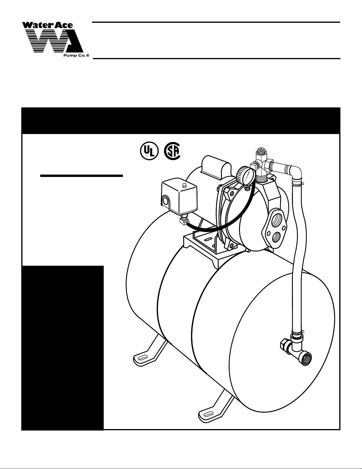
JET TANK SYSTEM
EASTERN
CONSUMER HOT-LINE: 1-800-942-3343 • MONDAY - FRIDAY • 7 AM to 5 PM
STANDARD
TIME
JET TANK
SYSTEM
with 7-gallon
diaphragm
pressure
tank
MODEL R-30-T7
1/3 Horse Power
Convertible Pump
WARRANTY
PRODUCT DEFECTS
CO VERED TWELVE
MONTHS FROM
R
pump only
®
DATE OF PURCHASE
OR EIGHTEEN
MONTHS FROM
DATE OF MANUFACTURE, WHICHEVER
COMES FIRST. RECEIPT AND PRODUCT DATE CODE
REQUIRED FOR
WARRANTY CLAIM.
WATER ACE PUMP COMPANY • ASHLAND, OHIO 44805-1969
23833A343
Page 2
IMPORTANT INSTRUCTIONS BEFORE INSTALLATION
Failure to follow these instructions may cause serious bodily injury and/or property damage.
Warranty void if product modified, drilled,
painted, or altered in any way; if used to
!
WARNING
pump hot water, or to pump liquids other
than water (such as but not limited to chemicals, fertilizers, flammable liquids, herbicides, mud,
tar, cement, wood chips); or otherwise abused.
1. Before installing or servicing your pump, BE CER-
TAIN pump power source is disconnected.
2. All installation and electrical wiring must adhere to
state and local codes and must be complete before
priming the pump. Check with appropriate community
agencies, or contact your local electrical and pump
professionals.
3. Pump should be installed in a dry, convenient
location which is close to the well and provides ample
space for installation and servicing the well. A dry
basement, pit, or utility room is an excellent choice
when allowed by law.
4. CALL AN ELECTRICIAN WHEN IN DOUBT. Pump
should be connected to a separate electrical circuit
directly from main switch. There must be a fuse box or
circuit breaker installed in this line. Plugging into existing outlets may cause low voltage at motor, resulting in
blown fuses, tripping of motor overload, or burned out
motor. Refer to electrical diagrams on following
page for electrical connections.
5. It is mandatory that a permanent ground connection
be made from the pump to the grounding bar at the
service panel. Do not connect pump to a power supply
until permanently grounded. For maximum safety,
ground the pump to a circuit equipped with a fault
interrupter device.
6. Motor Grounding Instructions: WARNING
Reduced risk of electric shock during operation of this
pump requires the provision of acceptable grounding.
Caution: Failure to ground this unit properly may
result in severe electrical shock. If the means of
connection to the supply-connection box is other than
grounded metal conduit, ground the pump back to the
service by connecting a copper conductor, at least the
size of the circuit conductors supplying the pump, to the
grounding screw provided within the wiring compartment. NOTE: N.E.C. requires pumps be grounded at
installation.
7. Voltage of power supply must match the voltage of
the pump which is factory preset to 115V, but may be
rewired for 230V (see following page).
8. During installation, cover well to prevent foreign
matter from contaminating the well or later damaging
the pump during operation. Test well water for purity.
Chlorination may be necessary. Check local Health
Department for proper testing and recommendations.
9. Hand pump new wells until clear. Sand or other
sediment will seriously damage the pump.
10.The 7-gallon diaphragm pressure tank is factory
preset to 30 PSI. It must be reset to 18 PSI for
proper system operation. Use an air gauge to
measure pressure in tank as air is released.
11. The following may cause severe damage to pump
and/or piping and will void warranty:
• Failure to protect pump and piping against below
freezing temperatures.
• Pumping chemicals or corrosive liquids.
• Running the pump dry. Follow priming instructions
on pages 4 or 8, depending on the installation.
•
Using extension cords.
•
Pumping gasoline or other flammable liquids.
•
Using this pump in or near a swimming pool.
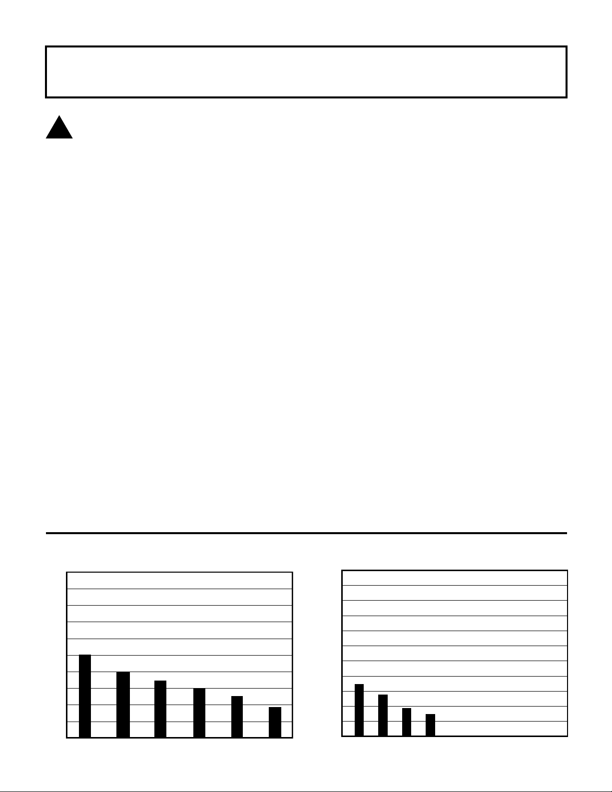
SHALLOW WELL PUMP CAPACITIES
20
18
16
14
12
10
8
6
4
2
GALLONS PER MINUTE AT 30 PSI PRESSURE
0
0
23833A343
510152025
PUMPING DEPTH IN FEET
11
10
9
8
7
6
5
4
3
2
GALLONS PER MINUTE AT 30 PSI PRESSURE
1
0
2
DEEP WELL PUMP CAPACITIES
30
40 50 60 70 80 90 100 110
PUMPING DEPTH IN FEET
Page 3
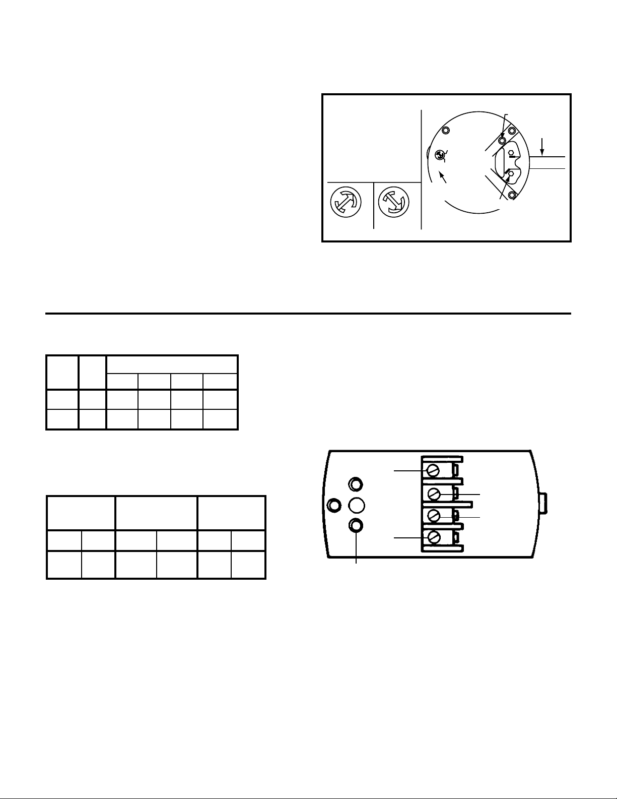
USE COPPER CONDUCTORS ONLY
VOLTAGE SELECTOR
AT REAR OF MOTOR
(USE NEEDLE
NOSE PLIERS)
PULL SELECTOR -
ROTATE - REINSERT
115
230
115V
230V
L2
L1
HIGH
VOLTAGE
LOW
VOLTAGE
VOLTAGE
SELECTOR
TERMINAL BOARD
GRD
UNGROUNDED
LINE
FINDING THE DEPTH OF YOUR WELL
The jet tank system installs differently depending
on the depth of your well. Tie a small but heavy
weight to the end of a piece of string (be sure there is
enough string; some wells are very deep). Lower the
weight into the well until it reaches the bottom. Take up
the slack and mark the string at ground level. Pull the
weight out of the well and measure from the bottom of
the weight to the ground level mark. This is the depth
of your well. Subtract five feet from the depth of your
well. This number should not exceed the maximum
rated depth for your pump. If it does, it will greatly
hinder or prevent the proper operation of the pump.
115V OR 230V OPERATION
Your pump is equipped with one of two types of dual
voltage motors. Follow the instructions to wire the
motor for the proper voltage. The voltage of the pump
must match the voltage of the power supply.
IMPORTANT SELECT
CORRECT VOLTAGE
WIRE SELECTION GUIDE
VOLTAGE
115
230
NAME
PLATE
AMPS
10.6
MAX. WIRE LENGTH USING AWG SIZE
5.3
#14
118
475
#12 #10
189
756
1184
296
#8
464
1857
FUSE AND CIRCUIT
BREAKER SIZE GUIDE
STANDARD LINE
PLUG FUSE*
115V
230V
20 10 12 6-1/4 20 15
*For circuits not over 150 volts to ground.
LOW PEAK - CART. TYPE
FUSETRON - CART. TYPE
FUSTAT - PLUG TYPE*
115V
230V
CIRCUIT BREAKER
115V
230V
WIRING YOUR PUMP
Remove the cover from the pressure switch. Connect
the bare copper ground to the ground screw in the
pressure switch. Connect the power supply to the
terminals marked "Line" in the diagram below.
LINE
MOTOR
MOTOR
LINE
GROUND
23833A343
3
Page 4

PIPING
Plastic PVC pipe is shown in the illustrations, but
galvanized steel pipe may be used if desired. All piping
must be clean and free of all foreign matter to prevent
clogging. ALL JOINTS AND CONNECTIONS IN THE
WELL ASSEMBLY MUST BE AIRTIGHT. Even a pinhole leak will prevent the proper operation of the pump
(this is the most common problem). Use thread compound on all threaded joints unless specified otherwise.
DRAINING FOR SERVICING OR FOR WINTER
The pump should be drained before it is disconnected
for servicing or if it is in danger of freezing. To drain:
• Remove drain plug from bottom of pump case.
• Remove discharge tee to vent the pump.
• Drain all piping to a point 3 feet below ground level.
SHALLOW WELL PUMP INSTALLATION
For wells 25 feet or less in depth, the ejector may be
attached to the front of the tank-mounted jet pump. For
lower depths, the ejector must be placed down inside
the well (see DEEP WELL PUMP INSTALLATION). All
materials with part numbers are quality Water Ace parts.
General Materials
• One Jet Tank System #R-30-T7. Includes: 1/3 HP
jet pump mounted on a 7-gallon diaphragm pressure
tank, pressure gauge, and twin ejector with gasket,
bolts, venturi tubes, and foot valve.
• One can PVC cement (read instructions carefully)
• One can thread compound (read instructions carefully)
• Two male 1-1/4" PVC adapters
• Enough rigid 1-1/4" PVC pipe and couplings to reach
from bottom of well to pump.
• One 4" well seal #RWS4-1012 with vent plug
• One 1-1/4" PVC elbow
Tools Needed for all pump installations
Pipe wrench, pipe clamp, crescent wrench, slot screwdriver, 24-tooth hacksaw, knife or round file.
(4" DIAMETER CASED WELL)
REMINDER: ALL JOINTS AND CONNECTIONS MUST BE AIRTIGHT. A SINGLE PINHOLE LEAK WILL PREVENT THE PROPER OPERATION OF THE PUMP. USE THREAD
COMPOUND ON ALL THREADED CONNECTIONS UNLESS SPECIFIED OTHERWISE.
STEP
1
STEP
2
total length of rigid PVC pipe and
couplings to cement onto the 1-1/4"
male PVC adapter. Cement one
section of rigid PVC pipe to the PVC
adapter which is connected to the
foot valve, then lower the whole
assembly into the well, foot valve
first. Firmly clamp the end of the
rigid PVC pipe with a pipe clamp to
prevent the assembly from sliding
down into the well.
Thread 1-1/4" male PVC
adapter into foot valve.
Hand tighten, then tighten
1/4 turn with crescent
wrench.
Subtract five feet from the
depth of your well (See
page 3 "Finding the Depth
of Your Well"). This is the
1-1/4"
MALE PVC
ADAPTER
FOOT
VALVE
PVC
PIPE
SECTION
1-1/4"
MALE PVC
ADAPTER
FOOT
VALVE
STEP
3
Cement as many couplings and sections of
rigid PVC pipe as it
takes to equal the depth
of your well minus five
feet, then firmly clamp
the assembly with a
pipe clamp to prevent
assembly from sliding
down into the well.
23833A343
4
Page 5

STEP
4
so twelve inches of PVC pipe protrude from well seal. Alternately turn
bolts on well seal counterclockwise
until rubber gaskets are tight against
well casing and PVC pipe.
STEP
5
of PVC pipe before cementing
elbow. Smooth inside of any cut
PVC pipe with file or knife.
STEP
6
has two holes in its top.
Thread the venturi tube
(part #25881A281 stamped on the side) into larger hole
until snug. Put gasket over venturi tube so openings in
gasket line up with openings in ejector.
STEP
7
Remove pipe clamp and
slide Well Seal #RWS4-12
over PVC pipe and onto well
casing. Position assembly
Cement 1-1/4" PVC elbow
onto PVC pipe protruding
from well seal. If desired,
some length may be cut off
Open ejector
pack included
with your jet system. The ejector
Secure ejector and
gasket to front of tankmounted pump with
bolts provided. Thread
a 1-1/14" male PVC
adapter into front of
ejector.
GASKET
VENTURI
TUBE
EJECTOR
APPROX.
12" OF
PVC PIPE
PROTRUDING
FROM WELL
SEAL
WELL
SEAL
#RWS4-12
1-1/4"
PVC
ELBOW
TOP OF
PVC PIPE
PROTRUDING
FROM WELL
SEAL
BOLTS
EJECTOR
MALE PVC
ADAPTER
STEP 9
CONT'D
than 24 lbs. for the R520. If no pressure shows:
Stop motor, remove pressure gauge plug from pressure
regulator, add more water, and try again.
STEP
10
pressure gauge into pressure gauge plug. Make
sure all connections are
tightly sealed. Place a
large basin beneath diaphragm tank outlet. Start
motor. If pump is off-set
from well 4 feet or more, it
may take a few minutes
for pump to prime. Failure to prime in 5 minutes:
Stop motor, remove pressure gauge plug from discharge tee, add more water, try again. Allow pump to
run long enough to clear the well of sand or dirt and to
insure well will not run dry. Stop motor.
STEP
11
maximum water flow is obtained without
pressure dropping to zero. If pressure falls
completely, retighten adjustment screw and
read-just. Steady pressure must not be less
Thread pressure
gauge plug back
into discharge
tee. Thread
Connect the 1" tank outlet to the service line.
Total installation should look like the drawing
below.
STEP
8
pressure to 18 PSI using a tire gauge. This is vital to
proper operation of the system.
STEP
9
adjustment screw down tight.
If pump is properly primed a
high pressure will immediately
show on the pressure gauge.
With pump operating at high
pressure, slowly unscrew regulator adjustment screw until
Cement as much PVC pipe and couplings
needed to connect PVC elbow to male PVC
adapter in front of ejector. The diaphragm
pressure tank is preset to 30 PSI. Reset
Place a large bucket
beneath the pressure
regulator outlet. Start
motor. Turn regulator
PRESSURE
GAUGE
ADJUSTMENT
PRESSURE
REGULATOR
COMPLETE
SHALLOW WELL
INSTALLATION
23833A343
5
Page 6

DEEP WELL PUMP INSTALLATION
(4" DIAMETER CASED WELL)
For wells over 25, but not exceeding 60 feet in depth,
the twin ejector must be installed down inside the well
rather than attached to the front of the pump. Materials
with part numbers are quality Water Ace parts.
General Materials
• One Jet Tank System #R-30-T7. Includes: 1/3 HP
jet pump mounted on a 7-gallon diaphragm pressure
tank, pressure gauge, and twin ejector with
gasket, bolts, venturi tubes, and foot valve.
• One can PVC cement (read instructions carefully)
• One can thread compound (read instructions carefully)
• One 1-1/4" close nipple
• One 1" x 4" nipple
• One 1-1/4" x 5" nipple
• Two 1" female PVC adapters
• One 1" male PVC adapter
• Two 1-1/4" male PVC adapters
• Enough rigid 1-1/4" PVC pipe and couplings to reach
from bottom of well to pump (delivery pipe)
• Enough rigid 1" PVC pipe and couplings to reach
from bottom of well to pump (pressure pipe))
• One well seal #RWS4-1012
• One 1-1/4" PVC elbow
• One 1" PVC elbow
REMINDER: ALL JOINTS AND CONNECTIONS MUST BE AIRTIGHT. A SINGLE PINHOLE LEAK WILL PREVENT THE PROPER OPERATION OF THE PUMP. USE THREAD
COMPOUND ON ALL THREADED CONNECTIONS UNLESS SPECIFIED OTHERWISE.
STEP
1
STEP
2
larger hole until snug. Thread 1" x
5" nipple into smaller hole. Only
hand tighten venturi tube. Tighten
nipple 1/4 turn with pipe wrench.
Thread 1-1/4" close nipple
into foot valve. Thread the
other end of 1-1/4" close
nipple into bottom of twin
ejector. Hand tighten, then
tighten 1/4 turn with pipe
wrench.
The ejector has two holes in
the top of it. Thread venturi
tube (part #25881A281
stamped on the side) into
EJECTOR
1-1/4"
CLOSE
NIPPLE
FOOT
VALVE
1" X 5"
NIPPLE
VENTURI
TUBE
EJECTOR
STEP
5
Lower the assembly into
the well, foot valve first.
Use a pipe clamp to
prevent assembly for
sliding down into well.
Cement as many
couplings and sections
of rigid PVC pipe on
both sides of ejector as
it takes to equal the
depth of your well minus
five feet, then firmly
clamp assembly with a
pipe clamp to prevent it
from sliding down into
the well.
STEP
3
STEP
4
onto both the 1-1/4" male and 1"
female PVC adapters. Cement a
section of PVC pipe to each adapter.
23833A343
Thread a 1-1/4" male PVC
adapter over the venturi
tube and into ejector.
Thread a 1" female PVC
adapter onto 1" x 5" nipple.
Tighten adapters 1/4 turn
with crescent wrench.
Subtract five feet from the
depth of your well. This is
the total length of PVC pipe
and couplings to cement
1" FEMALE
PVC
ADAPTER
1"
PVC
PIPE
1-1/4" MALE
PVC
ADAPTER
1-1/4"
PVC
PIPE
STEP
6
assembly slide down into well. Position assembly so that twelve inches
of PVC pipes protrude from well
seal. Using crescent wrench, turn
bolts on well seal counterclockwise
until rubber gaskets are tight against
the well casing and the PVC pipes.
6
Remove pipe clamp and
slide well seal
over PVC pipes and onto
well casing. DO NOT let
#RWS4-1012
12" OF
PVC PIPE
PROTRUD-
ING FROM
WELL
SEAL
WELL SEAL
#RWS4-1212
Page 7

STEP
7
Cut 1" pipe 2" shorter than
the 1-1/4" pipe. Smooth
rough edges. Cement 1"
and 1-1/4" PVC elbows to
pipes protruding from the
well seal.
1-1/4" PVC
ELBOW
1" PVC
ELBOW
1" PIPE 2"
SHORTER
THAN 1-1/4"
PIPE
STEP
8
STEP
9
Thread 1-1/4" male PVC
adapter into top hole in front
of tank-mounted pump.
Thread 1" x 4" nipple into
bottom hole in front of pump.
Thread the 1" female PVC
adapter onto the 1" x 4"
nipple.
1 1/4" MALE
PVC
ADAPTER
1" x 4"
NIPPLE
1 1/4"
FEMALE
PVC
ADAPTER
STEP
10
1 1/4" PVC PIPE
Cement as
many sections and
couplings of
rigid 1" and
1-1/4" PVC pipe needed to connect the 1" female PVC
adapter and the 1-1/4" male PVC adapter to the 1" and
1-1/4" PVC elbows. The diaphragm pressure tank is
factory preset to 30 PSI. Reset the pressure to 18
PSI using a tire gauge. This is vital to the proper
operation of the system. Remove pressure gauge plug.
1" PVC PIPE
COMPLETE
DEEP WELL
INSTALLATION
CAUTION: If you change pressure switch settings,
set the cut-off pressure low enough to shut off the
pump. The recommended pressure is 2 PSI below
your pump cut-off pressure. Example: if a 20-40 PSI
pressure switch is being used, tank pressure should
be 18 PSI. If a valve shuts off and the cut-off setting
is too high, the pump will run continuously without
water flow causing overheating and serious damage.
STEP
11
adjustment screw down tight.
If pump is properly primed a
high pressure will immediately
show on the pressure gauge.
With pump operating at high
pressure, slowly unscrew reg-
ulator adjustment screw until
maximum water flow is obtain-
ed without pressure dropping to zero. If pressure falls
completely, retighten adjustment screw and re-adjust.
Steady pressure must not be less than 24 lbs. for the
R520 and 32 lbs. for the R100. If no pressure shows:
Stop motor, remove pressure gauge plug from pressure
regulator, add more water, and try again. Complete
installation should look like the drawing to the right.
23833A343
Place a large bucket
beneath the pressure
regulator outlet. Start
motor. Turn regulator
REGULATOR
ADJUSTMENT
SCREW
7
Page 8

TROUBLESHOOTING CHECKLIST (CAUTION: SHUT OFF POWER TO PUMP)
PROBLEM
Pump will not prime
Pump delivers water
for a period of time,
then stops pumping
Pump does not deliver rated capacity
Motor overheats and
shuts off (overload)
Pump delivers water
but will not shut off
POSSIBLE CAUSES
• Not enough water. Stop motor, remove pressure gauge plug, and fill case with water.
• Pump wired incorrectly.
• Plugged venturi tube or nozzle.
• Foot valve is sitting in sand or mud, or is stuck shut, or leaks.
• Low well water level. In deep wells, the ejector as well as the foot valve must be below
water level.
• Leaks. Check all connections for airtightness.
• Low well water level. Use a water-level tester while pump is operating.
• Plugged venturi tube, nozzle, or impeller parts.
• Plugged venturi or nozzle.
• Faulty pressure gauge resulting in false readings.
• In deep wells, the operating pressure may be too high.
• Low well water level. Use a water-level tester while pump is operating.
• Over-submergence of ejector. In deep wells, if ejector is more than 10 feet below
pumping level, pumping capacity is reduced.
• In deep wells, the ejector may have improper size and depth setting.
• Motor voltage does not match power supply voltage. See pages 2 and 3.
• Improper wire size. See Wire Size Guide on page 3.
• Impeller is rubbing against pump case.
• Impeller neck is worn.
• Defective pressure switch.
• The tube connecting the two brass fittings may be clogged.
• Tank precharge pressure too high. Tank precharge pressure must be 1-2 pounds less
than switch turn-on setting.
• In deep wells, the water level may be going below limit of ejector. Use water-level
tester while pump is operating.
Pressure switch
turns on and off
every few seconds
Motor fails or does
not operate properly
• Galvanized storage tank is waterlogged.
• Leaky foot valve.
• Too much tank pressure.
• If within Warranty, return pump/motor unit to place of purchase (with proof of purchase)
for exchange.
LIMITED WARRANTY
WATER ACE PUMP CO. will repair or replace for the original user any portion of a new
Water Ace product which proves defective due to materials or workmanship of WATER ACE
PUMP CO. Contact the nearest authorized WATER ACE PUMP CO. dealer for warranty
service. WATER ACE PUMP CO. shall possess the sole right to determine whether to repair
or replace defective equipment, parts or components. THIS WARRANTY DOES NOT
COVER DAMAGE DUE TO LIGHTNING OR OTHER CONDITIONS BEYOND THE
CONTROL OF WATER ACE PUMP CO.
PUMPS: Warranted 12 months from date of purchase or 18 months from date of
manufacture, whichever occurs first. Receipt and product date code required for warranty
claim.
LABOR & COSTS: WATER ACE PUMP CO. shall IN NO EVENT be liable for the cost of
field labor or other charges incurred by any customer in removing and/or reaffixing any
WATER ACE PUMP product. part or component.
THIS WARRANTY WILL NOT APPLY: (a) to defects or malfunctions resulting from failure to
properly install, operate, or maintain the unit in accordance with printed instructions provided;
(b) to failures resulting from abuse, accident, or negligence; (c) to normal maintenance
services and the parts used in connection with such service; (d) to units which are not
installed in accordance with applicable local codes, ordinances, and good trade practices; (e)
if the unit is moved from its original installation location; (f) if unit is used for purposes other
than for what it was designed and manufactured.
PRODUCT IMPROVEMENTS: WATER ACE PUMP CO. reserves the right to change or
improve its products or any component without obligation to provide such a change or
improvement for units previously sold and/or shipped.
WARRANTY EXCLUSIONS: After the expiration of this warranty period, THERE WILL BE
NO WARRANTIES INCLUDING ANY IMPLIED WARRANTIES OF MERCHANTABILITY OR
FITNESS FOR ANY PARTICULAR PURPOSE ON ANY SPECIFIC WATER ACE PUMP
PRODUCT. Some states do not allow limitations on how long an implied warranty lasts, so
the above limitation may not apply to you. No warranties or representations at any time
made by any representative of WATER ACE PUMP CO. shall vary or expand the provisions
hereof.
LIABILITY LIMITATION: IN NO EVENT SHALL WATER ACE PUMP CO. BE LIABLE FOR
CONSEQUENTIAL, INCIDENTAL OR SPECIAL DAMAGES RESULTING FROM OR
RELATED IN ANY MANNER TO ANY WATER ACE PUMP PRODUCT OR PARTS. Some
states do not allow the exclusion or limitation of incidental or consequential damages, so the
above limitation may not apply to you. This Warranty gives you specific legal rights. You
may have other rights which vary from state to state. In the absence of suitable proof of
purchase date, the effective date of this warranty will be based upon the date of manufacture
plus 180 days.
Direct all Notices, etc. to:
Myers Parkway, Ashland, OH 44805-1969
Product Warranty and Return Dept., WATER ACE PUMP CO., 1101
23833A343
Water Ace Pump Co. • 1101 Myers Parkway • Ashland, Ohio 44805-1969
7/95
Page 9

REPLACEMENT PARTS
112 2 325 4
16
11
REF.
22
NO.
1
2
3
4
5
6
7
8
9
10
11
12
13
17
21
13, 19, 20
PART NUMBER
20929D501
05003A000
24349B000
23188A005
05004A015
05004A087
05126A013
05916A171
05920A173
06190A001
25800A500
10649A120
11933A002
DESCRIPTION
PUMP
PRESSURE GAUGE
REGULATOR
HOSE ADAPTER
BUSHING
BUSHING
PIPE TEE
PIPE NIPPLE
HOSE
T.O.E. NIPPLE
TANK
TUBE
SHIM (2 required)
14
24
23
15
18
9
10
16
7
REF.
NO.
14
15
16
17
18
19
20
21
22
23
24
25
JET TANK SYSTEM
MODEL R-30-T7
PART NUMBER
24859C500
19101A019
14740A001
15760A510
19277A001
19100A029
19109A012
23188A002
25579A108
08728A006
25881A281
23188A001
HOSE CLAMP (2 required)
REGULATOR SWITCH
DESCRIPTION
EJECTOR BODY
SCREW (2 required)
GASKET
SCREW (2 required)
NUT (2 required)
FITTING
EMBLEM
NOZZLE
VENTURI TUBE
FITTING
23833A343
Water Ace Pump Co. • 1101 Myers Parkway • Ashland, OH 44805
7/95
Page 10

REVISION TO PARTS LIST
If a 3/4" x 3/4" regulator is used, follow the replacement parts
list found in the jet tank system installation manual.
Ref.
Part Number Description
No.
3
4
5
6
8
21
25443A000
05762A055
05004A016
05004A087
05916A191
23188A002
3/4" Regulator
3/4" x 1" Elbow
3/4" x 1/4" Reducer Bushing
3/4" x 1" Reducer Bushing
3/4" x 3" Nipple
1/4" Barbed Fitting
If a 1" x 1" regulator is used, the following parts will be
different than the parts list found in the jet tank system
installation manual.
Replaced by
Part Number
25443A001
05762A009
05004A035
—
05427A250
23188A001
1" Regulator
1" Elbow
1" x 1/4" Reducer Bushing
Not Required
1" x 3-1/2" Nipple
1/8"" Barbed Fitting
Description
Retain these instructions for future reference.
23833A343
Water Ace Pump Co. • 1101 Myers Parkway • Ashland, OH 44805
7/95
 Loading...