

Page 1

User’s Manual
Powerline 200M
Ethernet Bridge
Page 2

1
Index
1. Powerline Networking Installation ....................................................................................................................... 2
1.1 Simple step to install Powerline Networking ..................................................................................... 2
1.2 Application Block Diagram ............................................................................................................... 3
1.3 Benefits........................................................................................................................................... 5
1.4 Features.......................................................................................................................................... 5
1.5 Package Contents ........................................................................................................................... 5
1.6 LED Definitions ............................................................................................................................... 6
1.7 System Requirements ..................................................................................................................... 6
2. Powerline Networking Utility ............................................................................................................................... 7
2.1 User Interface - Network Information Tab....................................................................................... 10
2.2 User Interface - Encryption Tab.......................................................................................................11
2.3 User Interface - Link Information Tab ............................................................................................. 12
2.4 User Interface - Connection Information Tab .................................................................................. 13
2.5 User Interface - QoS Tab ............................................................................................................... 15
2.5 User Interface - QoS Tab ............................................................................................................... 15
3. Push Button Setting ......................................................................................................................................... 18
4. Trouble Shooting.............................................................................................................................................. 21
Page 3
2
1. Powerline Networking Installation
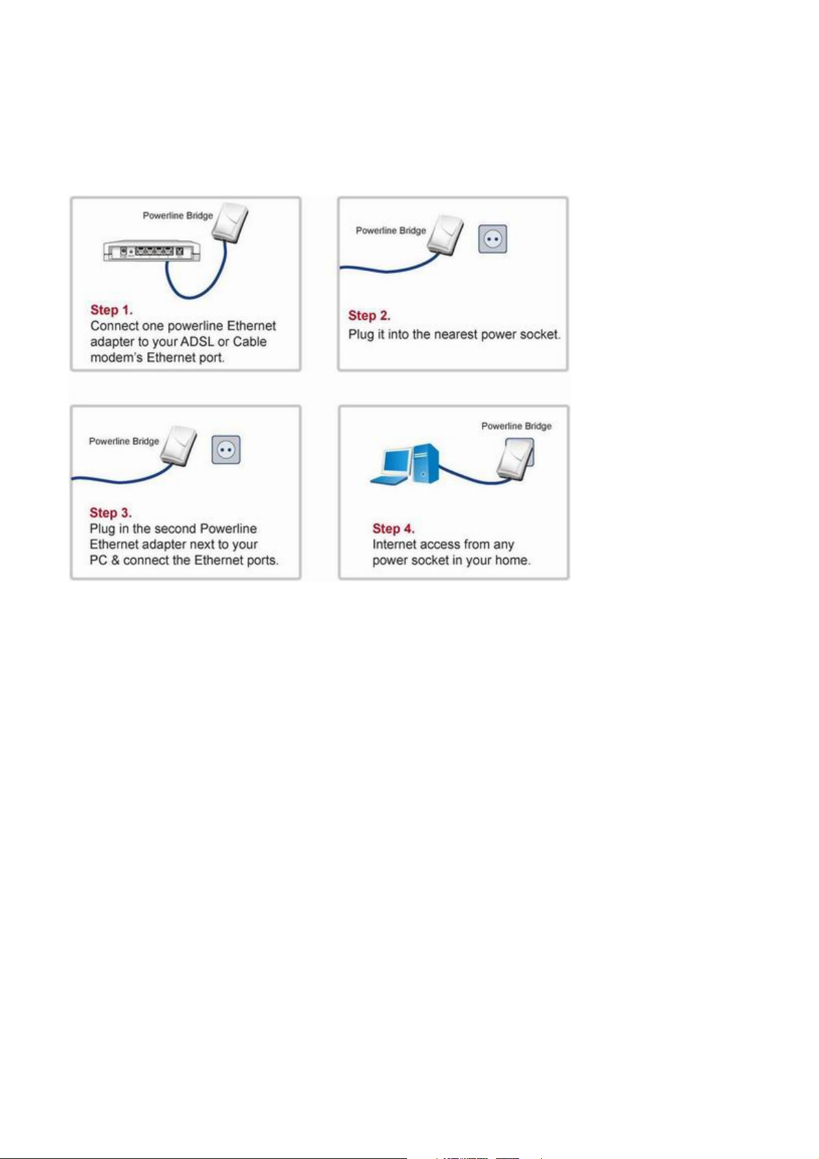
1.1 Simple step to install Powerline Networking
Page 4
3
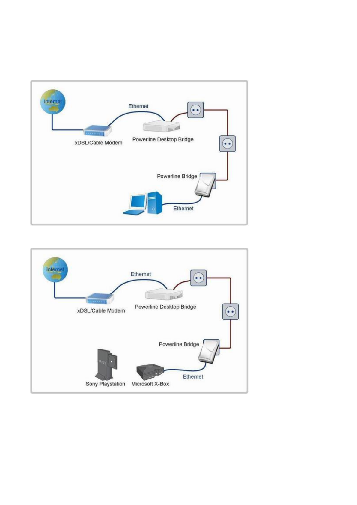
1.2 Application Block Diagram
1.2.1 Internet ADSL with one computer via power outlet
1.2.2 Online game via power outlet
Page 5
4
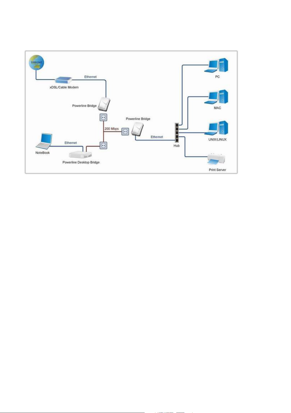
1.2.3 Internet ADSL and Home Networking via power outlet
Page 6

5
1.3 Benefits
‧
Data transfers at up to 200 Mbps over the household power circuit
‧
Ranges of 200 meters
‧
No need new wires for Home networking
‧
Deliver the benefits of Ethernet without the wiring expense
‧
Send even large files between PCs without long waits
‧
High-speed Internet and DVD-quality video streaming
‧
Fully compliant with IEEE 802.3, IEEE 802.3u
‧
Privacy through DES encryption
1.4 Features
‧
Use the home's existing Powerline
‧
Support coexist with Powerline 85M or 14M bridges
‧
Easy to install
‧
Throughout the whole house, just use your power circuit to access the Internet or PC network
‧
Orthogonal Frequency Division Multiplexing for high data reliability in noisy media conditions
‧
Integrated Enhanced Quality of Service(QoS) features: Eight levels of prioritized random access, contention
free access, and segment bursting
‧
Up to 200Mbps data rate on Powerline
‧
Provide 128-bit AES Link Encryption with key management for secure Powerline communications
‧
LEDs indicate status
1.5 Package Contents
‧
Powerline 200M Ethernet Bridge unit
‧
Powerline Network Management CD
‧
Quick Installation Guide
‧
Category 5 cable
Page 7
6
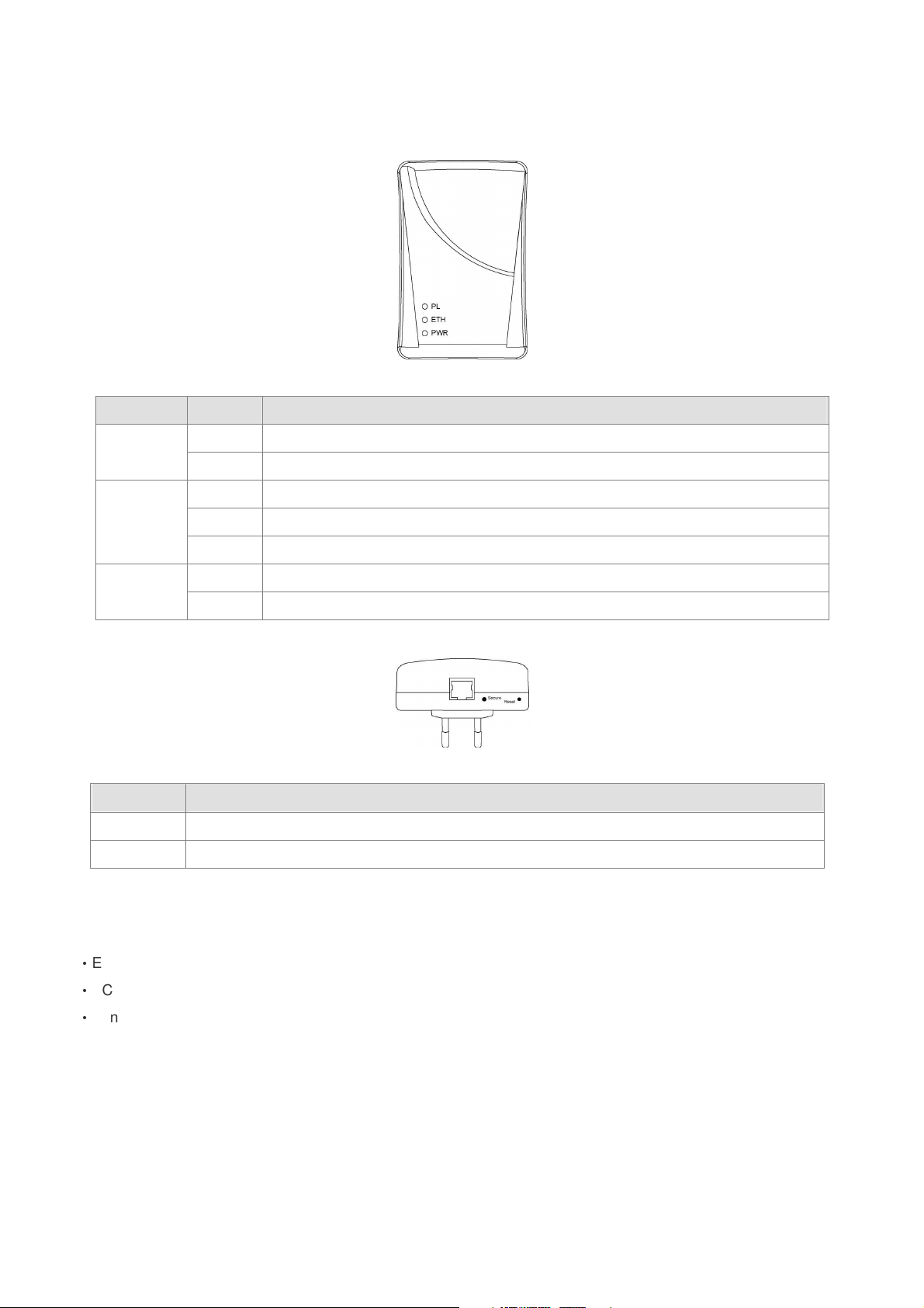
1.6 LED Definitions
LED State Description
PL
ETH
PWR
Button Description
Secure Button can auto secure and group the Powerline devices.
Reset Push this button can reset to the factory default settings.
ON Powerline network activity.
OFF Search or no Powerline network activity.
ON Ethernet connection is OK.
Flashing Data transfer.
OFF No link to Ethernet.
ON Power on.
OFF Powerline off or failure.
1.7 System Requirements
‧
Ethernet device
‧
AC power outlet
‧
Windows system for encryption setup
Page 8

7
2. Powerline Networking Utility
Note
The Powerline Device can auto detect the other Powerline bridges which plug in the same power circuit, you don’t
need to use this Powerline utility except you want to encryption all the Powerline devices as the same group or you
can not access the other computers.
Introduction of Configuration Utility
The Configuration Utility for Windows OS enables the user to find Powerline Ethernet devices on the Powerline
network; measures data rate performance, ensures privacy, performs diagnostics and secures Powerline networks.
Configuration Utility Setup
Installation of the Utility
Please verify that no other Powerline Management Utilities are installed before installing this product. If other utilities
are installed, uninstall them and restart before installing this software. The utility only support Windows 2000, XP
and 2003.
To install, insert the Windows OS Configuration Utility Setup utility CD-ROM into the computer's CD-ROM drive. The
Setup utility shall run automatically. Alternatively this can also be done manually by double clicking the setup.exe file
on the CD. The CD will launch an installation utility similar to the one shown in Figure 2.1.1.
Click the Utility to enter the Utility install page. Please make sure if your windows OS doesn’t install the .NET
Framework, please install it first, otherwise, the Powerline Utility will work not properly. If already installed the .NET
framework, please install the Powerline Utility directly. After that, it will pop up the setup wizard as the Figure 2.1.2,
please click the Next button to continue.
Page 9

8
Figure 2.1.1.
Figure 2.1.2.
Page 10

9
Common Features of Tabbed Windows
Status Bar
The status bar, along the bottom of each window, contains five fields that provide important network information.
• The first field contains the status of the Device Manager in respect to connection to a Powerline device.
‘Connected’ indicates a local device has been identified. ‘Not connected’ indicates no device has been found.
• The read only drop down box of the second field lists the available network adapters found on the system. Use the
drop down box to select the appropriate adapter for connection to the local Powerline device.
• The third field lists the MAC Address of the connected node.
• The fourth field lists the firmware version of the locally connected node.
• The fifth field serves as a status indicator for the various download functions of the Device Manager, displaying a
progress bar and messages pertaining to the various stages of operation.
Page 11

10
2.1 User Interface - Network Information Tab
This window is an Operation Analysis window that reveals Network information in three categories: CCo Information,
Connected STA Information and Topology.
2.1.1. Topology
The ‘Topology’ group shows the TEI, MAC Address, Bridged MAC Address and the transmit (Tx) and receive (Rx)
Coded and Raw PHY rates for all nodes on the network (other than the local STA).
The ‘Coded’ rates exclude FEC bits.
The ‘Raw’ rate is the actual channel bit rate. The Raw rate is determined by carrier bit loading and the applied
HomePlug AV Tone Mask which utilizes 917 carriers out of a possible 1155.
If all carriers were to be utilized with maximum bit loading on all 1155 carriers, the Raw channel rate would be
approximately 250 Mbps.
With the HomePlug AV Tone Mask applied, the maximum Raw channel rate is approximately 200 Mbps (198 Mbps
maximum actual).
Factory Defaults: Press this button can reset the settings to the factory default.
Figure 1: Network Information Tab
Page 12

11
2.2 User Interface - Encryption Tab
This Encryption window is used to set or change the network password on a remote device identified by its DAK
password. Clicking the ‘Set’ button sets the entered passwords. If the DAK password field is left blank, then clicking
the ‘Set’ button will set local device with the entered password. The ‘Set Encryption for Remote device’ checkbox
should be selected to set the Network Password for the remote device.
The Push Button controls box includes the ‘Action’ drop down box that provides a choice of three actions {Simple
Connect, NMK Randomize and AVLN Status} signaled to the device when the ‘Simulate Button Push’ button is
pressed. Additionally, two configuration parameters are exposed in the ‘PIB Controls’ sub-group box.
Press Set button to save the settings.
Figure 2: Encryption Tab
Page 13

12
2.3 User Interface - Link Information Tab
2.3.1. Link Characteristics Box
The context of the link is identified with the Source and Destination address boxes in the Link Characteristics group
box. The Source Address defaults to the address of the device selected in the Device Selection box on the lower left
of the tab and the Destination Address is selected from a drop down list.
2.3.2. Ethernet Controls
The Ethernet Controls are populated once the Retrieve button is pushed and indicate the PHY settings of both ends
of the link.
2.3.3. Control and Statistics Groups
The members of the Statistics group are populated or cleared based on the radio button selection in the Controls
group and the pressing of the Execute button. The lower status window provides feedback regarding the processing
of the activity.
Figure 3: Link Information Tab
Page 14

13
2.4 User Interface - Connection Information Tab
The Connection Information window is used to acquire statistics for both transmit and receive operations in the local
or remote network.
2.4.1. Connection Select
CSMA : the Destination Address (DA) drop-down menu may be used to select ALL devices or specific devices in the
network.
In addition, Channel Access (CA) priority can be defined using the second drop-down menu. The DM allows only
certain valid combinations that can be selected by the user. The following table describes the combinations.
Device Selection Destination Address (DA) Channel Access priority Allowed
Local device All All Yes
Local device Remote device All Yes
Local device Remote device CA0 or CA1 or CA2 or CA3 Yes
Local device Local device Any No
Remote device All All Yes
Remote device Local device All Yes
Remote device Local device CA0 or CA1 or CA2 or CA3 Yes
Remote device Remote device Any No
2.4.2. Transmission and Reception Statistics
The ‘Transmission and Reception Statistics’ groups return operational data regarding MPDU’s and packet data unit
handling. Results shown in these fields provide valuable connection quality information.
Transmission Statistics
MPDUs Ack'd MPDUs sent with SACK received
MPDUs Collided MPDUs sent with no SACK received
MPDUs Failed MPDUs sent with SACK ‘out of resources’ received
Reception Statistics
MPDUs Recvd MPDUs received and acknowledged
MPDUs Failed MPDUs not received due to out resources (SACK sent)
The ‘Enable Statistics’ button is used to acquire the operational data and the ‘Clear Statistics’ button is used to clear
the fields of data. The values shown by the Device manager is a cumulative total of the packet data that was
collected from the start of either the ‘Enable Statistics’ button or the ‘Clear Statistics’ button click.
Page 15

14
Figure 4: Connection Information Tab
Page 16

15
2.5 User Interface - QoS Tab
QoS requirements are different for various data types such as streaming video or music, voice and raw data. To
provide higher QoS for streaming data, priority levels can be set using tags at the beginning of data frames. Virtual
Local Area Network (VLAN) 802.1p priority tags on Ethernet frames are used to specify 8 (0 – 7) levels of ‘user
priority’. HomePlug AV powerline allows for 4 levels of Channel Access Priority (CAP (0 – 3)). Therefore, the 8
levels of VLAN Ethernet tags must be mapped to the 4 levels of CAP priority, where CAP 3 is the highest priority and
CAP 0 is the lowest. CAP 3 priority might be used for voice and network management frames, CAP 2 is used for
streaming video and music while CAP 1 and CAP 0 are used for data. Mapping VLAN tags or TOS bits to CAP levels
is easily done using the VLAN Priority Mapping function on the QoS tab window.
2.5.1 List Views
The QoS tab includes two list views to provide simple channel access priority (CAP) classification for individual MAC
addresses and IP Ports. There is a collective limit of eight across both lists. No delimiters, colons, or dashes are
allowed in the MAC address format.
To write these to the PIB, and other QoS related values found on this tab, the Download PIB checkbox found on the
Configuration tab must be checked before exercising the Write button.
2.5.2 Priority Mapping
The ‘Priority Mapping’ group contains both VLAN and TOS Bit mapping capability. When selected, packets matching
the VLAN or TOS Bit priority will be assigned the Powerline contention priority (Channel Access Priority, CAP) as set
in the corresponding dropdown box. If a packet has both VLAN and TOS in it, VLAN will override TOS.
Page 17

16
2.5.3 Default CAP
The ‘Default CAP’ group allows for default priority mapping of packets that do not have a VLAN or TOS bit (or if
these are disabled). Settings are available for Unicast (directed to a host).
IGMP (default CAP 3):
sets the channel access priority for IGMP frames - these are the group management frames,
not the stream data.
Unicast (default CAP 1):
sets the default channel access priority for unicast frames not matching any other classification
or mapping.
IGMP managed Multicast Stream (Fixed to CAP 2):
sets the default channel access priority for stream data belonging to a snooped IGMP multicast
group.
Multicast/Broadcast - sets the default CAP for multicast frames not in a snooped group and for
broadcast frames.
After making CAP settings, clicking the Write button will commit these, along with the values from the Configuration
tab, to NVRAM on the connected device.
Page 18

17
2.5.4. IGMP
The ‘IGMP’ group includes controls to disable the query timeouts. Checking the ‘Override Defaults’ box will enable
the other boxes as choices.
2.5.5. Priority TTL Value
The ‘Priority TTL Value’ determines the life span (Time to live) of each packet in the buffer of the AV device that will
be sent over the powerline subsequently. This value can be varied from 10 msec to 65000 msec which can be
mapped to different levels of Channel access priority traffic. The default values used are stored in the PIB file as
shown below:
CA0 traffic: 2000 msec (used for TCP data traffic)
CA1 traffic: 2000 msec (used for TCP data traffic)
CA2 traffic: 300 msec (used for UDP video/music traffic)
CA3 traffic: 300 msec (used for VoIP traffic)
Intellon highly recommends that the 300 msec and 2000 msec default settings not be changed because they are
optimized for the above stated traffic.
Figure 5: QoS Tab
Page 19

18
3. Push Button Setting
There are 2 buttons in this device, one is Reset button the other is Secure button.
Reset: Push this button can reset to the factory default settings. Be careful, when you press the reset button,
please make sure unplug (remove) the Ethernet cable (RJ-45cable) first, and then press the reset button.
After press the reset button (the time need < 3 sec) and then wait the PWR LED light again. Don’t power off
when the device is in reset process.
Secure button can auto secure and group the Powerline devices, the follow is the scenario for secure button.
Two Push Button trigger state conditions
“Adder state” for a device providing the NMK for an existing AVLN
“Joiner state” for a device that will join an AVLN
Pushing buttons on any two devices results in one of them becoming an “adder” and the other one a “joiner”
Three possible scenarios
Unassociated device joining an existing AVLN
– Two Unassociated devices joining to form a new AVLN
– Special case: one device is a CCo, the other is a STA
Two Associated devices joining to form an AVLN with a new NMK
Page 20

19
Possible Use Case Scenario 1: Unassociated device joining existing AVLN
Possible Use Case Scenario 2: Two devices joining to form new AVLN
Before this scenario begin, please make sure to press each device secure button > 10 sec till all LEDs
re-flash to generate the random network password key first.
Possible Use Case Scenario 3: Reset
Page 21

20
Page 22

21
4. Trouble Shooting
1. Why my utility can not work properly after finish install steps?
Ans:
Please follow the steps to check the problem.
1. Check the Control panel for Microsoft .NET Framework install status, if you don’t install this, please
install it.
2. Reinstall the utility again, you can remove it and reinstall the utility again.
2. What kind of windows OS can install the Powerline utility?
Ans:
Now the Powerline utility only supports Windows 2000, XP and 2003.
3. Why the throughput of Powerline 200M bridge is bad?
Ans:
Please follow the steps to check the problem.
1. Due to the master/slave structure, you need to avoid plugging two Powerline bridge in the same time,
so you had better plug the Powerline to the power outlet sequence.
2. Please unplug the Powerline bridge and plug again, please remember plug them in sequence.
Check the Powerline utility and check the throughput again.
4. Why the Powerine 200M device can not work stable?
Ans:
In some respects, User had better to adjust the NB/PC NIC's connection type setting to 100MBaseTx half
duplex while connect to powerline 200M device. It will keep the performance to the best status and stable.
When user found the link is unstable or not good, please change the NIC's connection type setting to half
duplex.
 Loading...