


ISDN-TA/MLP
User’s Manual

Table of contents
Chapter 1 Introduction
1.1 Product description
1.2 Internet Access
1.3 CompuServe Access
1.4 T-Online Access
1.5 Remote LAN Access
1.6 License
Chapter 2 Installation
The external model of ISDN-TA
2.1 Packing list
2.2 Look at the TA
2.3 Installation preparation
2.4 Installing the TA
2.5 Communications Software Configuration
Chapter 3 Using the TA
3.1 Configuration for Internet
3.2 Configuration for CompuServe
3.3 Configuration for end-to-end data transfer
Chapter 4 AT Command Set and response codes
4.1 AT Commands
4.2 S Registers
4.3 Result Codes
Chapter 5 Configuration Hints
5.1 Configuration under Windows
5.2 Configuration the TA
5.3 Error analysis under Windows NT
5.4 Configuration under Windows NT4.0
Appendix A Specifications
Appendix B RS-232D Connections
Appendix C Flash program updating procedure
Appendix D Special Note for application software
D.1 Note for the NetManage Internet Chameleon
D.2 Note for the RVS-COM Software application

Chapter 1 Introduction
Congratulations! You have purchased the terminal adaptor with the finest, smartest,
high-speed features.
This Documentation is valid for the products:
ISDN-TA/MLP: External ISDN terminal adaptor with two analog interface.
The term of 'TA' below represents ISDN-TA/MLP for the indication of general features.
1.1 Product Description
TA is an ISDN terminal adaptor connecting a existing PC (or other device with. Serial
port) to the ISDN. It gives access to on-line services as the Internet, CompuServe and
T-Online and is also suitable for a remote LAN access. You can see it as a digital
replacement for an analog modem.
If you are connecting to the Internet you will be able to use all of the features offered
by your Internet access program. These features vary from program to program.
They may include browsing, uploading and downloading files, using electronic mail,
and accessing World Wide Web sites and chat rooms.
If you are telecommuting, you will use the office network just as you would if you were
at work. For example, if you normally log into the office network for file retrieval and
storage, you will use the same procedure from your home PC to open and save files.
If you use electronic mail over a local area network (LAN) at work, you will be able to
use the same electronic mail program at your home.
You can also use the TA to connect to a single remote PC that contains another TA
via ISDN line. This allows you to use peer-to-peer network programs for file sharing
between two PCs. It also means you can transfer files between two PCs via common
communication software.
To work with TA you need.
- a ISDN Basic Rate Interface (BRI) (replacing an analogue telephone line)
- a PC with online software for a modem terminal program
The serial port of the PC should be capable of a data rate of up to 230400 bps.
This might require an additional PC card for external model.

The TA includes the following features:
-Compatible with ISDN central office switches for DSS1
-Status display LED
-Operating parameters saved in nonvolatile memory
-ISDN AT command set
-Convent configuration command
-Multi-link PPP (128Kbps)/ PPP async-to-sync HDLC transparent for main
Internet service provider
-Two optional analog telephone interface enable you to connect an analog
terminal (e.g. telephone, fax, PBX, or modem) to an ISDN Basic Rate line
-ITU-T V.120 - for CompuServe or others Internet service provider
-ITU-T X.75/ T.70NL - for T-Online Videotext service
1.2 Internet Access
There are several ways to access the Internet via ISDN.
- by Multi-Link PPP asynchronous-to-synchronous HDLC transparent
- by PPP asynchronous-to-synchronous HDLC transparent
- by bit rate adapt ion V.120
It depends on the access facilities of your Internet service provider (ISP) or
Point-of-presence (POP) which one you may use.
1.3 CompuServe Access
CompuServe is accessed via ISDN by the protocol V.120 or X.75.
1.4 T-Online
T-Online (German Online Service) is accessed via ISDN by the protocol T.70NL/X.75.
1.5 Remote LAN Access
To access a LAN remotely via ISDN you have to choose the appropriate protocol that
is used by the ISDN router on the LAN.
1.6 License
TA has the CE European approval
TA fulfills the European safety requirements IEC 60 950.
Connect the TA only to S0-interfaces with SELV (Safety Extra Low Voltage) related to
EN60950.

The TA is also conform to the European regulations of EMC. EN50081-1, here
EN55022 Class B, for electromagnetic fielded mission and EN50082-1 for tolerance
against electromagnetic interference.
This ISDN Terminal Adapter is only to be used in private or business premises for the
sending or receiving of data and speech together with a personal computer.
Unauthorized modifications, which are not described in this user's manual, are not
allowed.

Chapter 2 Installation
This manual describes installation of the external terminal adaptor. Set up your TA
according to hardware configuration you get.
2.1 Packing List
The complete package should include:
1) The terminal adaptor unit
2) The user's manual
3) The RJ-45 modular ISDN cable
4) A power adaptor
5) Communication software (optional)
6) DTE interface serial cable (optional)
Carefully inspect for shipping damage. If any is found, immediately repack the TA into
the original packing material and contact your dealer.
2.2 Look at the TA
There are several LED indicators at the front panel of your TA as shown in the
schematic below (Fig2-1, the front panel of the TA) each of which displays an
operational status:
Fig2-1: The front panel of the TA
Light Meaning Function
PR Power ready ON The TA is turned on.
OFF The TA is turned off.
SD Send data ON You are either entering a command to the TA or
transmitting data to a remote computer.
OFF The TA is neither receiving a command from you
RD Receive data ON The TA is receiving data from a remote computer.
The TA is configured for full-duplex, and its echo
feature is turned on, when you send a command to
nor transmitting data to a remote computer.
your TA, it will return a response to you.
OFF The TA is neither receiving data from a remote
computer nor receiving a command from you.
AA Autoanswer FLASH Ringing.
ON Auto answer.
A1 POTS1 OFF POTS is idle.
A2 POTS2 FLASH Call is in progress.
ON POTS is active.
LNK S/T Link OFF ISDN S/T interface is idle.
ON ISDN S/T interface is active.
128 ML-PPP ON Two B-Channel are active for a ML-PPP
connection.
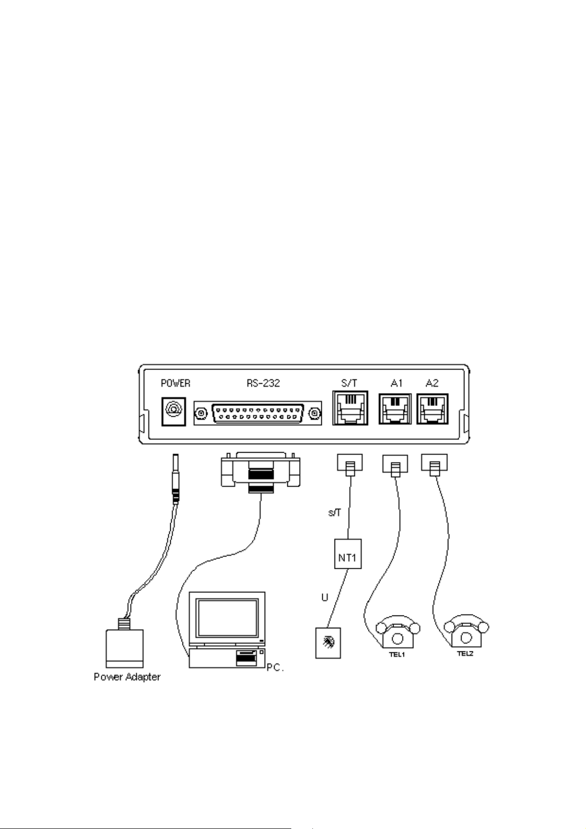
The rear panel of the TA
On the rear panel of the TA are the power switch, the power jack, and RS-232D
connector and one modular jack, as shown in the schematic below.
Fig 2-2 The rear panel of the TA

The power switch
Toggling the power switch to ''ON'' turns the TA on, while toggling the switch to ''OFF''
turns the TA off. It is recommended that you always turn on your computer prior to
turning on the TA, and turn off your TA prior to turning off the computer.
The power jack & power adaptor
The power jack for the power adaptor which is included with your TA. This TA
MUST use an AC 12V power adaptor. Always use the one supplied with your TA.
Use of another power adaptor may cause safety problems
The RS-232D connector
The RS-232D connector can be connected to the serial port of the computer through a
RS-232D cable. Your computer or terminal must have an industrial standard RS-232D
serial port to use this TA. Please have an RS-232D port (available from your dealer)
installed if your computer does not have one.
The TA can be connected to the serial port of the computer via a serial cable. Be sure
to specify the appropriate type of connector (DB-25 or DB-9, male or female) for each
end of the cable. Your TA follows industry standards in wiring the pins of the cable
connectors, therefore, any cable that would connect a TA to your computer will work.
Refer to Appendix C RS-232D connection, or consult your dealer if you need the
pin assignment of the connector.
The modular ISDN jack
The one modular jack labeled " TO S/T ", located on the right side of the rear panel,
is for the connecting cables from the ISDN BRI line.
Be sure that the ISDN line condition is in good order before connecting the TA. Test it
by lifting for example an ISDN telephone handset and listening for a clear dial tone.
Note: We strongly recommend that you connect the TA directly to the central
office outside ISDN telephone line. Do not hook your TA to a business
ISDN system (PBX) unless the system is guaranteed to be good enough
for correct protocol handling data transmission and call control.
The analog telephone jack (A1 / A2)
The interface enables you to connect an analog terminal (e.g. telephone, fax, PBX,
or modem) to an ISDN Basic Rate line. Any convert tonal analog terminal
equipment which supports DTMF tone dialing can be plugged into the RJ-11 jack.

2.3 Installation Preparation
To install your TA the following items are required:
- A S0 interface (basic rate interface) with IAE plug (Western RJ).
- A PC with the appropriate Internet software installed.
2.4 Installing the TA
The distance between the computer and the TA will be determined by the length of
the RS-232D cable. A suitable location for your TA should be:
1) Near a reliable AC power source.
2) Close to a good quality ISDN telephone line.( According to I.430)
3) Where the LED indicators on the front panel are clearly visible.
4) Where the power switch could be easily reached.
5) Where you are able to monitor the TA's carrier signal.
To connect the hardware, Please follow the procedures below:
1) Make sure both the TA and the computer are turned off.
2) Connect the TA to the computer:
Use a RS-232D cable between the TA and the computer. Plug the male DB-25
connector of the RS-232D cable to the TA.
Then, plug the other end of the cable to your computer serial port. Fix all of
the screws on the connectors.
For the use of data rates up to 11.5K bps. The RS-232 cable should not be too
long.
Note: Write down the computer serial port number ( COM1, COM2, COM3,
COM4) to which you have connected the TA. This port number
should be identical to the number listed in the communication software
configuration.
3) Connect the TA to a ISDN telephone line:
Plug one end of the supplied ISDN telephone cable to the outlet.
Then, plug the other end to the jack marked "S / T" on the rear panel of the TA.
4) Connect the power supply to the TA:
Insert the plug of the power adaptor into the jack marked "POWER" on the
rear panel of the TA.
Please check if the factory settings fit with your environment. The factory setting is
described in the parameter list show in chapter "AT Command Set".

If you want to change the factory default setting, please do the following steps:
- Connect the TA to ISDN interface and connect the power supply to the mains
socket.
- Start a terminal emulation program on your PC.
- Setup the parameter of the TA from the terminal emulation and save the
parameter.
- Leave your terminal emulation and start your application program.
2.5 Communications Software Configuration (for all of models)
Most popular communications software packages will work well with your TA. You
may, however, prefer to purchase the recommended TelixTM communications
software package, which should be available from your dealer.
Turn on your computer first, then the TA. Boot the communications software and
check the following parameters:
1) The serial port number.
2) The communication speed and protocol.
3) Data format: data bit, stop bit, parity.
Set the serial port number to COM1, COM2, COM3 or COM4 according to which your
TA is connected. Note that one port should be assigned to only one device;
otherwise, the two devices will conflict with each other.
To use the TA to dial a remote TA or server, the protocol, speed and data format of
both side should be set to match each other. For example, if the remote side you are
going to dial supports V.120, 57600bps, 8 data bits, no parity, 1 stop bit; you should
set communication software to the same parameters.
Software configuration tips
If your computer is an IBM PC, XT, AT, 386, 486 or Pentium and you are using
ProcommTM, BitcommTM, CrosstalkTM or most other communications software
packages, the factory default settings of the TA should correct.
However, if you are using SmartcomTM, the software requires that the DTR (Data
Terminal Ready) always be forced true. You should insert the command &D0 into the
dialing prefix.

To use the terminal in manual operation, you should insert both commands &C0 and
&D0. For example, AT&C0&D0DT.
To configure your TA for auto-answering, set register S0 to a non-zero value. For
example, inserting S0=2 into the command string instructs the TA to auto-answer
incoming calls calls after the second ring.
To meet some special requirements, you may need to change some other parameters,
such as the duplex mode, the auto line feed, the emulate, and so on. Consult an
experienced modem or ISDN TA user or your dealer for the required adjustments.
Regrettably, we are unable to describe software configuration procedures in greater
detail, as the procedures vary from software package to software package, from
computer to computer, and depend on the application. Refer to your software manual
for more detailed information. If you have any difficulty, consult an experienced
modem or ISDN TA user or your dealer.
Getting Started
Now boot the communications software and instruct it to dial a server, or remote
computer with a TA. Your TA should proceed with the call and establish a
connection automatically. Then you can:
1) Read or send electronic mail.
2) View the most updated news or information.
3) Upload or download computer programs.
4) Transmit or receive a text message or spread sheet data.
5) Play interactive games with the remote user.
With your TA completely installed, discover the fun and convenience of data
communication.

Chapter 3 Using the TA
3.1 Configuration for Internet
To access the Internet via ISDN you have to have a contract with a Internet service
provider (ISP) who runs an ISDN access. To configure the TA you need the
following information of the ISP:
- ISDN telephone number
This phone number is used to enter the Internet every time you call.
- Layer 2 protocol
This protocol should be configured in the TA, via command or Window
setup procedure.
- Internet access protocol
These protocol stacks are provided by the Internet software. For example:
TCP/IP, PPP protocol.
To configure the Internet access software on the PC you need some additional
information like TCP/IP address, user name, password etc. Please refer to the
software manual.
3.2 Configuration for CompuServe
To access the CompuServe network via ISDN, you have to have a contract with
CompuServe. To configure the TA you need the following information from
CompuServe:
- ISDN telephone number
This phone number is used to enter the Internet every time you call.
- Layer 2 protocol: V.120 async
This protocol should be configured in the TA via typing "AT!Z=5".
You can use a CompuServe access by a running standard terminal emulation.
3.3 Configuration for end-to-end data transfer
To transfer data at end-to-end point via ISDN you have to a terminal program
access. For configuration you have to setup the following parameter:
- ISDN telephone number at both side
This phone number is used to enter the remote site every time you call.
- Layer 2 protocol
Give one kind of the initial string as follows at TA of both side:
1.AT!Z=5 <Enter> -use V.120

or 2.AT!Z=6 <Enter> -use V.110 (option)
When V.120 is used, DTE speed can be selected from300, 1200, 2400,
4800, 9600, 19200, 38400, 57600, 115200bps.
When V.110 is used, DTE speed can be selected from 115200, 57600,
38400, 19200, 14400, 9600, 7200, 4800, 2400, 1200bps.
- Select the appropriate file transfer protocol like Z-MODEM in your terminal
program after connection to send the file you want.
Chapter 4 AT Command Set
With the exception of the A/ command all of commands begin with the prefix AT
and are terminated with <Enter>. Corrections in a command line are done with
<Backspace>. A command line has a maximum of 40 characters, the command line
is automatically cancelled by longer input. Blanks are ignored, capital/small letters
are not significant.
The parameter settings of the TA obtained via using the AT commands are
permanently stored by typing AT&W and are not lost by reset or by leaving the AT
command mode.
To enter the AT command mode during an active data connection you must use
the following sequence: ("scope sequence")
at least 1 sec pause <+><+><+> 1 sec pause
The time gap between all three plus signs may not exceed 1 sec.
The escape sequence is transmitted transparent to the remote device.
4.1 AT Commands
/ Repeats the previous command.
A Answer incoming calls
Dn Places an originating call. If the call is rejected, an appropriate response
such as "NO CARRIER", "BUSY", OR "NO DIALTONE" will be displayed
command mode will be re-entered. The commands "DT" and "DP" are
identically as the "D" command.
DS DIAL using saved number

E0 Disable character echo in command state
E1 Enable character echo in command state (default)
H Hung-up
I0 Product identification
I1 Eprom checksum
I3 Model function
I6 Version product name
O Go back to connection state from escape mode
Q0 Return response codes after command input (default)
Q1 Do not return response codes
Sr=n SET register value
This command is used to alter an internal "Modem" register.
This command supports three different means of accessing S-register values:
Decimal form: Sr=d -Set register "r" to decimal value "d".
Sr? -Display value of register "r" in decimal.
Examples: S23=39
OK
S23?
39
OK
Hexadecimal from: Sr:=x -Set register "r" to hexadecimal value "x".“x”.
Sr:? -Display register "r" in hexadecimal.
Examples: S23:=E2
OK
S23:?
E2
OK
Binary form: Sr:=x -Set register "r", bit "p" to binary value "b".
Sr:? -Display register "r" in binary.
Examplex: S23.?
10010100
OK
S23.?

00010100
OK
Sr? QUERY of register
V0 Display results in numeric form
V1 Display results in verbose form (default)
X0 base responses (default)
X1 extended responses
X2 extended ISDN responses
X3 DCE connection speed responses
Z The active configuration will be reset to stored configuration
Z1 Recall system default setting
&C0 DCD always on
&C1 DCD on after connection (default)
&D2 Terminates the call after delay specified in S25 when DTR drops(default)
&F Recall factory default
&K0 Disables flow control
&K3 Enables RTS/CTS Flow Control (default)
&K4 Enables XON/XOFF Flow Control
&K5 Enables Transparent XON
&K6 Enables RTS/CTS and XON/XOFF
&M0 Asynchronous mode (default)
&R0 CTS tracks RTS
&R1 CTS on (default)
&S0 DSR on
&S1 DSR on after connection
&V Display current configuration

&W Store current configuration in non-volatile memory
&Z=x Store phone number
\S Display current configuration
!B0 Disable MSN
!B1 Enable MSN
!In=x Set calling party number sending
n-0 Pots 1
n-1 Pots 2
n-2 DTE
x-0 Disable
x-2 Enable
!Nn=x Set MSN number
n-0 Pots 1
n-1 Pots 2
n-2 DTE
x-0 Set phone number
!Z=n Set operating protocol
5- V.120 Mode
7- Raw HDLC
9- PPP
10- X.75 Transparent
14- MLPPP
15- BOD
22- T.70 BTX
23- T.90 NL
*Nn Set UART Baud Rate
*NA Enable Autobaud (all other values disable) for UART
*N0 300bps fixed for UART baud rate
*N1 1200bps fixed for UART baud rate
*N2 2400bps fixed for UART baud rate
*N3 4800bps fixed for UART baud rate

*N4 9600bps fixed for UART baud rate
*N5 19200bps fixed for UART baud rate
*N6 38400bps fixed for UART baud rate
*N7 57.6kbps fixed for UART baud rate
*N9 115.2kbps fixed for UART baud rate
*N14 230.4kbps fixed for UART baud rate
*N15 Reserved
*N16 Reserved
*N17 Reserved
4.2 Register Description
S0 0-255. 0 disables Auto_Answer, a non-zero value will Auto_Answer an
incoming call.
S2 0-127. The "escape character", in decimal. The default is 43 ("+")
S3 0-127. The "carriage return", or command terminator character.
The default is 13(<CR>).
S4 0-127. The "line feed" character. The default is 10 (<CR>).
S5 0-127. The "backspace" character. The default is 8 (<BS>).
S12 0-255. Number of milliseconds for escape characters. The default is 50.
S14 This register is bit-mapped for use with various options. The default is 138.
Bit0-Ext. baud rates
0-38400
1-19200
Bit1-Command echo (ATE Command)
0-no echo
1-echo
Bit2-Result codes (ATQ Command)
0-enabled
1-disabled
Bit3-Verbose mode (ATV Command)
0-terse
1-verbose
Bit4-Abort code
0-ON
1-OFF
Bit5-Not Used
Bit6-Not Used
Bit7-Originate/Answer

0-answer
1-original
S21 This register is bit-mapped of use with various options. The default is 19.
Bit1-0-Not Used
Bit2-CTS behavior
0-CTS on
1-CTS track RTS
Bit4-3-DTR behavior
00-DTR ignored
01-Reserved
10-DTR falling terminates call
Bit5-DCD behavior
0-DCD on
1-DCD on after connection
Bit6-DSR behavior
0-DSR on
1-DSR on after connection
Bit7-Reserved
S22 0-255. This register provides a "bit-map" of options for result code usage.
0 -Display CONNECT Message Only.
64 -Display standard CONNECT Message.
112 -Display Enhanced ISDN CONNECT Messages
S23 This register is bit-mapped to control baud rate and parity as follows.
Bit 0- Not Used
Bits3-1-Baud rate
000-300bps
001-Use extended baudrate sets
010-1200bps
011-2400bps
100-4800bps
101-9600bps
110-19200bps
111-38400bps
Bits4-5-Parity
00-Even

01-Space
10-Odd
11-Mark/None
Bits7-6-Extended baudrates
00-57600bps*
01-78400bps
10-115200bps
11-Use other baudrates noted in S24.
S24 This register is bit-mapped to control autobaud and extra baudrates.
The default is 192.
Bits3-0-Extra baudrates.
0000-7200bps
0001-14.4kbps
0010-28.8kbps
0011-153.6kbps
0100-230.4kbps
0101-460.8kbps
0110-921.6kbps
0111-1111-Reserved
Bit4-6-reserved
Bit7-Autobaud select
0-Disabled
1-Enabled
S25 0-255. Delay for DTR management. The default is 5.
S26 0-255. Delay for CTS tracking RTS. The default is 1.
S32 XON flow control character. The default is 17.
S33 XOFF flow control character. The default is 19.
S39 This register stores the Flow Control Selection. The default value is 3.
0-No Flow Control
1-Reserved
2-Reserved
3-RTS/CTS Flow Control
4-XON/XOFF Flow Control
5-Transparent Flow Control
6-Both RTS/CTS and XON/XOFF Flow Control
255-7-Reserved

S40 This register stores the POTS Dialing Timeout Selection. The default value
is 5.
S54 Number of rings to wait before disconnect if S0=0. The default is 30.
4.3 Result codes
0 OK 19 CONNECT 56000
1 CONNECT 20 CONNECT 64000
2 RING 21 CONNECT 57600
3 NO CARRIER 22 CONNECT 76800
4 ERROR 23 CONNECT 115200
5 CONNECT 1200 24 CONNECT 7200
6 NO DIALTONE 25 CONNECT 14400
7 BUSY 26 CONNECT 28800
8 NO ANSWER 27 CONNECT 153600
9 CONNECT 600 28 CONNCET 230400
10 CONNECT 2400 29 CONNECT 460800
11 CONNECT 4800 30 CONNECT 921600
12 CONNECT 9600
13 CONNECT VOICE
15 (aborted!)
16 CONNECT 19200
17 CONNECT 38400
18 CONNECT 48000

Chapter 5 Configuration Hints
The following configurations should used when connecting a PC via TA to an Internet
provider.
5.1 Configuration under Windows
Installation for Windows Environment.
5.1-1 Install ISDN TA via plug and play
<Step01> Select Start -> Settings -> Control panel -> System -> Device Manager
-> Refresh.

<Step02> Insert driver diskette to floppy disk drives Click
<Step03> The ISDN TA will use "PnP" driver, Click Next
The "PnP" driver won't use any protocol command to the device,
The appropriate protocol depending upon the B channel setting in
Configuration utility.

<Step04> Click Finish .
5.1-2 Adding virtual modems connecting with ISDN TA
<Step01> Select Start -> Settings -> Control panel -> Modems -> Add ->
“ Don't detect my modem; I will select it from a list".

<Step02> Insert driver diskette to floppy disk devices.
<Step03> Click "Have Disk" and browse to devices such as A:\
Select the ISDNMLP1.inf file.
<Step04> "ISDN TA Multilink PPP" is for 128K Internet Access. The used protocol
in B channels are Multilink PPP.
"ISDN TA PPP" is for 64K Internet Access. The used protocol in
B Channel is Async-to-Sync PPP conversion.
"ISDN TA X75 Transparent", "ISDN TA V120" are for most BBS
Access and file transfer.
"ISDN TA HDLC Transparent", "ISDN TA T70" and "ISDN TA T90" are
for special connection protocol.
These modems are added one by one manually in turn. Each modem
Will use the appropriate protocol command to ISDN TA terminal adapter
When you select it to make a connection. Select the modem that
you require from the list and Click Next.

<Step05> Select the Com Port which connects to modem, Click Next.
5.1-3 About Configuration Utility for Windows 95 / 98
<Step01> Insert driver diskette to floppy disk devices.
<Step02> Make Sure ISDN TA is ready.
<Step03> Select Start -> Run -> "CONFIGTA.EXE"

<Step04> Select "Setup" for COM port, protocol, S-register and Multiple Subscriber
Number Setting, Select "F/W Upgrade" for flash download.
<Step05> Select COM Port location and baud rate which connect to the ISDN TA

<Step06> Click "Default", The ISDN TA will restore default profile. If you modify
some setting such as Bch Protocol or Country. you need click "Apply"
then "Save" to save to NVRAM.
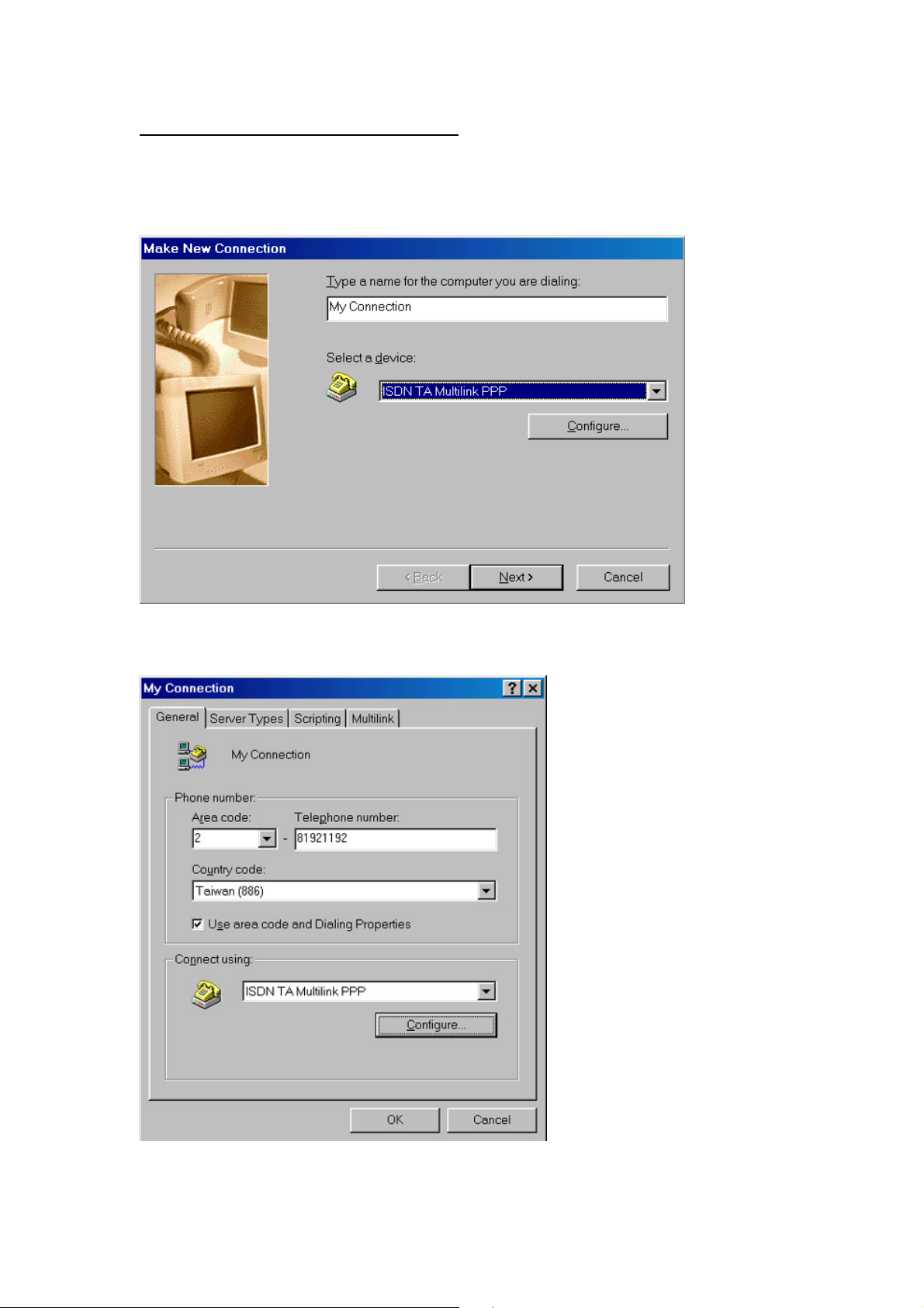
5.1-4 Configure the Dial-Up Networking
<Step01> Select Start -> Programs -> Accessories -> Dial-Up Networking
-> Make New Connection. Select the ISDN TA Multilink PPP which
is connected to ISDN TA.
<Step02> Check and modify if necessary the properties of a connection.

5.2 Configuring the TA
The configuration of the TA is depend on the access type of the Internet provider. The
following types of access are mostly used for public ISDN access.
- HDLC asycn to sync conversion
This protocol has to be setup, if the service provider uses a access point where
the protocol PPP is or ML-PPP.
- V.120
Please get more information from your Internet provider if necessary.
5.3 Error analysis under Windows NT
To setup a protocol logging of the connection in B channel using PPP protocol
can be done in the following way:
- Enable logging information in the registry via executing %SystemRoot%
\system \REGEDT32.EXE:
HKEY_LOCAL_MACHINE \SYSTEM
CurrentControlSet \Services
RASMAN \Parameters
logging=1
PPP
logging=1
- You can find the log files in the following directory after running you
PPP connection:
%SystemRoot% \System32 \RAS \PPP.LOG
and %SystemRoot% \System32 \RAS \Device.log
To get a detailed error analysis please contact your supplier of the TA

5.4 Configuration under Windows NT4.0
5.4-1 Adding virtual modems connecting with ISDN TA
<Step01> Select Start -> Settings -> Control Panel -> Network -> Services.
<Step02> Select Remote Access Service -> Click Properties..
<Step03> Click Add -> Install Modem

<Step04> Check Add -> "Don't detect my modem, I will select it from a list"
then Click Next.
<Step05> Insert the driver diskette to floppy disk devices.
<Step06> Click "Have Disk" and browse to devices such as A:\
Select the ISDNMLP1.inf file.
<Step07> Select the modem type that you require from the list and then
Click Next.

<Step08> Select the Com Port which connects to modem, Click Next.
<Step09> After you install the modem, select the virtual modem in the RAS Capable
Devices field then Click OK.
<Step10> Select this virtual modem and Click the "Configure Tab" to set port usage
the Click OK.
<Step11> If you chose "dial out only" and then click the network tab; choose
"TCP/IP" for internet access.
5.4-2 Configure the Dial-Up Networking
<Step01> Select Start -> Programs -> Accessories -> Dial-Up Networking.
<Step02> Enter the name of Dial-Up account and Click Next.
<Step03> Enter the server type details for ISP and Click Next.
<Step04> Enter the phone number of ISP and Click Next.

<Step05> Click Finish.
<Step06> Click More to configure setting
<Step07> Click Dial to make a connection

Appendix A
Specifications
Terminal Adaptor Specifications
ISDN interface S/T interface
ITU-T I.430
ISDN standards DSS1 (Euro-ISDN) for Europe
INS Net-64 for Japan
NI-1 for USA
B channel protocol ML-PPP asynchronous-to synchronous HDLC transparent
PPP asynchronous-to-synchronous HDLC transparent
ITU-T V.120/64000 bps
ITU-T X.75/T.70NL
DTE data rate 1200 - 115200 bps (asynchronous)
Data format 8 data bits;1 or 2 stop bits; no parity
B channel speed 2 channel 64000 bps (synchronous)
Computer interface ITU-T V.24/EIA-232D/DB25 connector
Command set AT command set
Data rates 115200 to 1200 asynchronous
Operation Half duplex or Full duplex operation
Extra memory Modifiable non-volatile memory stores:
One configuration profile
Line requirements ISDN Basic Rate line (Order from your telephone company)
Pots Two Analog telephone interface for the conventional analog
telephone device (e.g. fax modem. or PBX)

Appendix B
RS-232D Connections
This appendix provides EIA RS-232D connector pin assignments and circuit
descriptions of each signal.
Answer on V.24/V.28/RS-232D pin assignments
CCITT DIN EIA I/O TEXT
1 - Protective Ground
2 103 D1 TD I Transmit data
3 104 D2 RD O Receive data
4 105 S2 RTS I Request to send
5 106 M2 CTS O Clear to send
6 107 M1 DSR O Data set ready
7 102 E2 GND - Signal ground
8 109 M5 DCD O Data carrier detect
20
108/1
108/2
22 125 M3 RI O Ring indicator
S1.1
DTR I Data terminal ready
S1.2

Appendix C
Flash program updating procedure
TA includes code which allows the user to update firmware in the FLASH without
removing it from TA's board. How to upgrade the code, please do the following
commands:
For mate: FLASHTA -COM x FILENAME.BIN
select the serial port your TA used
Example: FLASHTA -COM2 TAMLPE.BIN
Note: 1.During programming, don't turn the PC or TA off.
2.Don't use the DOS environment escape from Windows
The DOS environment "MUST" start from reboot.
Configuration Utility program for Windows:
This program allows the user to configure the TA and update firmware under
Windows.
Step1: Into the "START\RUN" icon
Step2: Insert the driver diskettes to Floppy
Step3: Run A:\ configta.exe
FLASHTA.EXE command parameters
The FLASH download program, FLASHTA.EXE, is a DOS real-mode program.
Its purpose is to read the ROM image binary file and transmit the contents to the TA
via a serial COM port using a packet protocol. FLASHTA.EXE accepts the following
command line parameters:

Parameter Required? Description
-COMx YES COM port to which the TA is attached.(COMx should
be from COM1 to COM4)
-IOxxxx Optional Specifies the IO port address of the COM port. The
value 'xxxx' should be a 3 or 4 digit hexadecimal
number specifying the port address. The default
addresses are:
COM1=3F8,COM2=2F8,COM3=3E8,COM4=2E8.
-IRQxx Optional Specifies the IO port interrupt level. The value 'xx' is a
one or two digit decimal number from 1 to 15. The
defaults values are:
COM1=4,COM2=3,COM3=4,COM4=3.
-Bxxxxxx Optional Specifies the maximum baud rate to be used. This is the
maximum rate at which FLASHIMG.EXE will attempt
to transmit data to the Ta(a lower rate may be used if
the program determines that reliable transmission
cannot occur at the higher rates.)The default value is
115200.
-F Optional If this parameter is present, the automatic revision level
checking is disabled and the FLASH download is
performed without verifying that a 'down-level' load is
being attempted.
-R Optional If this parameter is present the TA is assumed to be in
FLASH download mode, most probably as a result of
a previously aborted FLASH download attempt; no AT
command sequence will be sent (the sequence required
to place the TA in FLASH download mode).
filename YES File name or complete path name, if necessary, of the
ROM image binary file to be FLASHed into the TA.

Appendix D
Special Note for application software
D.1 Note for the NetManage Internet Chameleon
1. Configure the TA according to chapter 3 description prior to install the
NetManage Internet Chameleon.
2. Install the NetManage Internet Chameleon.
3. Start the Custom application by double-clicking its icon in the Internet
Chameleon program group.
4. Choose Open... from the File menu. Open the file tcpip. cfg.
5. Choose Interface type... from the Setup menu. Select PPP, and click OK.
6. Choose Host Name... from the Setup menu. Enter a name to identify your PC
and click OK.
7. Choose Port... from Communications of the Setup menu. Set the Connect field to
the COM port where your TA is attached. Then clear the Carrier detect
checkbox so that no X appears there. Click OK.
8. Choose Modem... from Communications of the Setup menu. In the field labeled
Modem Init, replace the current string displayed there with AT&C1&D2^M.
Then click OK.
9. Choose Dial... from Communications of the Setup menu. In the field labeled
Dial enter the ISDN telephone number for Internet access.
10. Choose Login... from Communications of the Setup menu. Enter your user
name and password from Internet service provider given.
11. Click the Connect menu item to actually connect to the Internet.
12. The Custom application must remain running while you are connected.
13. When you wish to disconnect from Internet, restore the Custom application
(if you minimized it) and select the Disconnect menu item.
D.2 Note for the RVS-COM software application
The TA works with RVS-COM Lite V1.52 or later version.
RVS Datetechnik GmbH
http://www.rvscom.com

Declaration of CE
This declaration of conformity is according to article 7(3) and article 10(2)
of the Council of European Communities of 3 May 1989.
The protection requirements according the Council Directive article 4
and Annex III are kept.
MODEL / TYPE: External ISDN Terminal Adapter ISDN-TA/MLP
This declaration is given from the manufacturer
submitted by
TRAINING RESEARCH CORPORATION
5F,. NO. 571, SEC. 7,
CHUNG HSIAO E. RD., TAIPEI,
TAIWAN, R. O. C.
To the judgment of the products with regard to electromagnetic compatibility
according following regulations:
EN 55 022 Class B
EN 50 082 - 1 (IEC 801 Part 2,4 / ENV 50140 / ENV 50141)
EN 60950
PART No.: 506-10071-01
 Loading...