

ACE Controls ACE MLS 64 Installation Instructions
23435 Industrial Park Drive
Farmington Hills, Michigan 48335
tel: 248.476.0213
fax: 248.476.2470
www.acecontrols.com
Air-Oil Tank Installation Instructions
Magnum Group Shock Absorbers
ACE MCA, MCS 33, 36, 45 and 64 Self-Compensating Series
ACE MAA, MAS, MLA, MLS 33, 36, 45 and 64 Adjustable Series
Maximum efficiency of operation can be obtained by
carefully following these instructions:
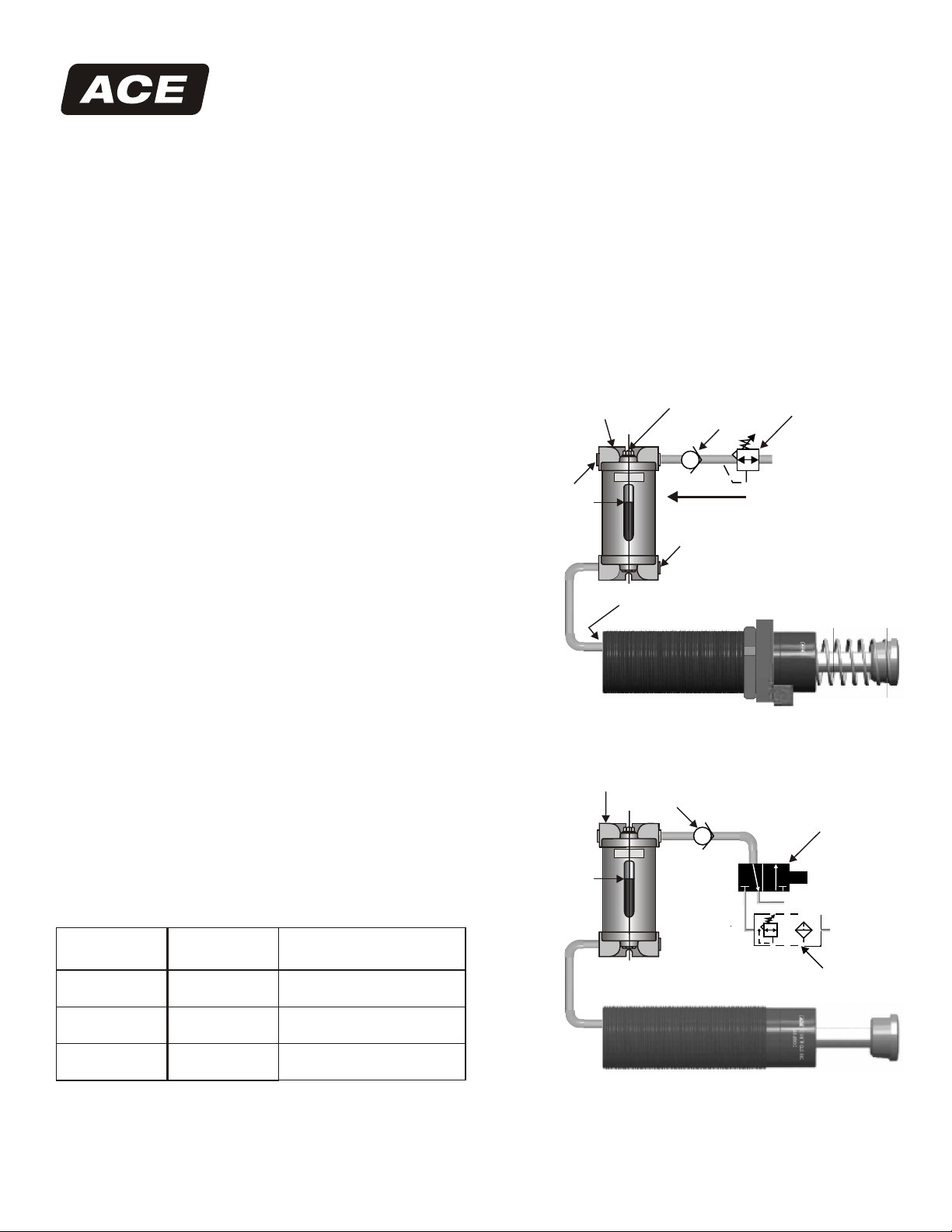
AIR-OIL TANK INSTALLATION (Figure 1)
Self-compensating models MCA and MCS as well as
adjustable models MAA, MAS, MLA and MLS are
pre-filled with ATF but must be connected to an
air-oil tank before use.
Install the proper ACE air-oil tank as close as possible
to, and physically higher than, the shock absorber. The
line connecting the shock absorber to the air-oil tank
must be free of kinks and loops. The inside diameter
of this line must be equal to, or greater than, that of the
port in the shock absorber.
Do not put a shut-off valve between the shock absorber
and the air-oil tank. Install a check valve in the air line
to the air-oil tank and plug the extra ports of the tank.
Fill the tank with ATF to the fill mark, with the rod
extended, and charge the system to between 50-100 psi
(3.4 - 6.8 bar)
AIR EXHAUST CIRCUIT FOR MODELS MCA, MAA
and MLA SHOCK ABSORBERS (Figure 2)
If the rod is to remain in the shock absorber after
decelerating the load, this type of installation is
necessary. If not built in, a special ACE check valve
should be used to eliminate misting of oil out of the
air-oil tank.
PROPER AIR-OIL TANK SIZE
Refer to the chart below for proper air-oil tank size in
relation to the specific Magnum Group series.
Figure 1
Air-Oil Tank
Plug
Figure 2
Air-Oil Tank
WARNING
Do not use near open flame
contents may be flammable
Do not fill
above this line
Inlet Port
WARNING
Do not use near open flame
contents may be flammable
Do not fill
above this line
Fill Plug
Check Valve
Plug
CV 3/8-F
Free
Flow
Regulator
MA 4550 2
CONTROLS INC.
3-Way Normal
Closed Valve
Sol
Exhaust
Series
33, 36
45
64
Air-Oil Tank
AO-1
AO-1
AO-3
ACE Controls Inc.
World leader in deceleration technology
ISO 9001:2000 Certified
Air-Oil Tank
(Re-circulating Circuit)
AO-3
AO-3
AO-6-91
Supply
Filter/
Regulator
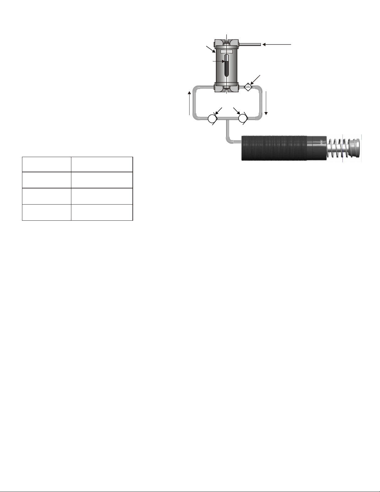
RE-CIRCULATING COOLING CIRCUIT FOR
MODELS MCA, MCS, MAA, MAS, MLA and
MLS (Figure 3)
This type of installation may be required when
ambient temperatures and/or cycle rates cause
the shock absorber to heat up beyond 150 F
0
(65 C).
0
Use high pressure 1,000 psi (69 bar) check valves
with a low cracking pressure of 5 psi (0.34 bar).
If a filter is to be used in this circuit, a 30 to 40
micron filter element with a 5 psi (0.34 bar) by-pass
is recommended. Consult factory for assistance.
LOCK NUT TORQUE SPECIFICATIONS
Refer to the chart below when installing shock
absorber lock nut.
Figure 3
Air-Oil Tank
WARNING
Do not use near open flame
contents may be flammable
Do not fill
above this line
High Pressure
Check Valve
Air Supply
Optional Filter
MA 4550 2
CONTROLS INC.
Model
MC, MA, ML
33, 36 Series
MC, MA, ML
45 Series
MC, MA, ML
64 Series
Torque/Lock Nut
54 - 59 ft-lbs
(74 - 81 Nm)
167 - 183 ft-lbs
(225 - 250 Nm)
560 - 610 ft-lbs
(755 - 830 Nm)
APPL YING APPROPRIATE TORQUE
WITHOUT CALIBRATED TOOLING
The following procedure may be utilized if
calibrated tooling is not available to torque
lock nut.
Note: it is assumed that all necessary
installation instructions have been followed
prior to this procedure.
1. After positioning the shock properly in relation
to the accessory (i.e. flange, collar, etc.) or
mounting surface, with the proper adhesive (if
applicable), finger tighten the lock nut against
the accessory or mounting surface until it can no
longer be turned.
2. Using appropriate equipment, tighten the
lock nut until it rotates 1/8 to 1/4 of a full rotation
(45 to 90 degrees) from the finger tight position.
ACE has determined that a lock nut secured in
this manner meets the torque specifications
listed in the chart above.
Notice
For Magnum Group 33 & 36 models
the torque specification for the male
connector, shipped loose, is 6-10 in-lbs
(0.68 - 1.13 Nm)
Side Port Torque Notice
For Magnum Group 33 & 36 Series
1/8” NPT, Torque 25-30 in-lbs (2.82-3.38 Nm)
For Magnum Group 45 & 64 Series
1/4” NPT, Torque 30-35 in-lbs (3.38-3.95)
ACE Controls Inc.
World leader in deceleration technology
ISO 9001:2000 Certified
ACE Form 17, Air-Oil Tank, Magnum
04/01/2004
 Loading...