

Page 1
Installation Instructions
1-1/2” Bore Adjustable Shock Absorber
23435 Industrial Park Drive
Farmington Hills, Michigan 48335
tel: 248.476.0213
fax: 248.476.2470
www.acecontrols.com
Maximum efficiency of operation can be obtained by
carefully following these instructions:
GENERAL
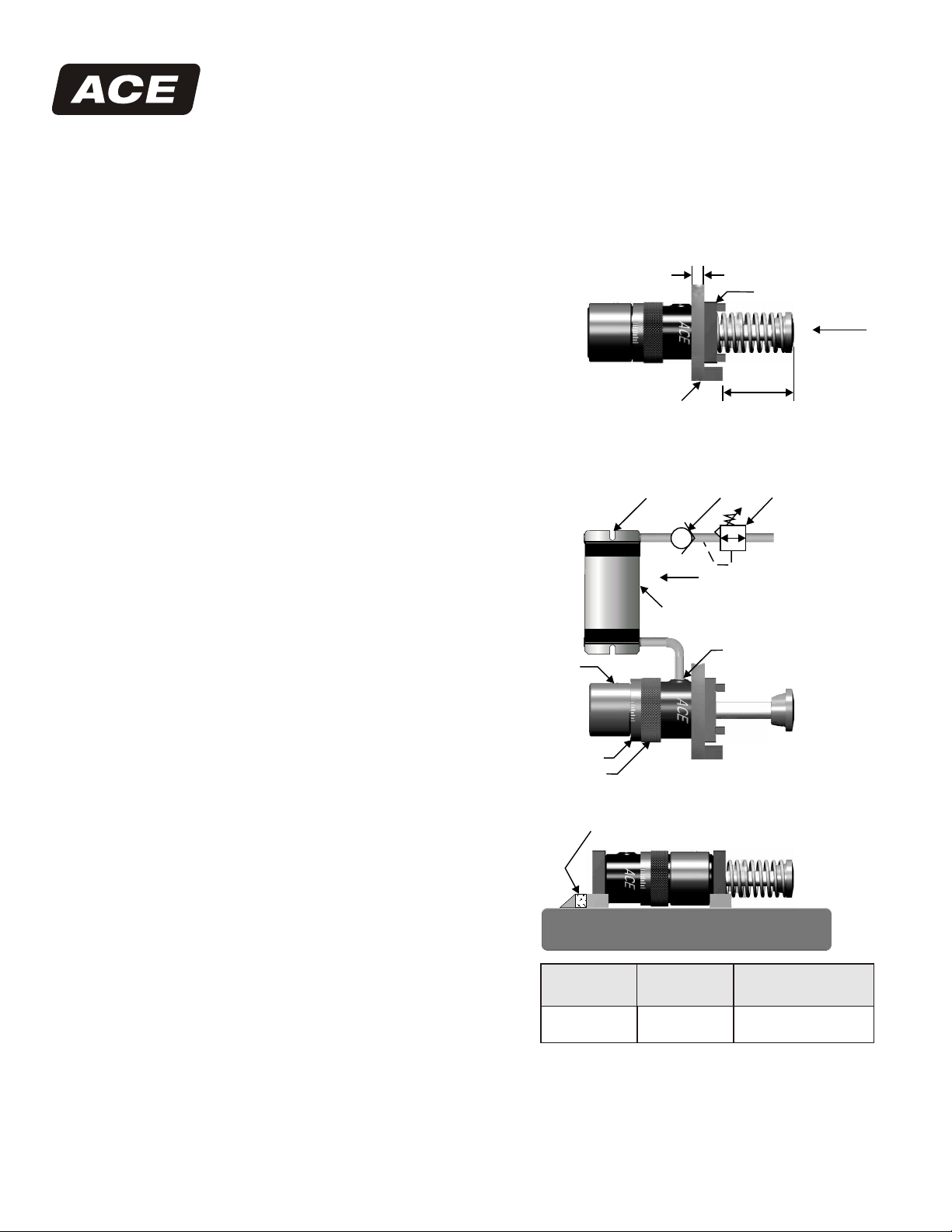
Install the adjustable shock absorber (Figure 1) on a
surface of sufficient strength. Align the shock absorber rod
end button with the load striking surface. This avoids side
loading (5 maximum). Use the full stroke of the shock
0
absorber up to the last 3/32 inch (2.5 mm) and provide a
solid mechanical stop to prevent bottoming out. To allow
maximum heat dissipation, DO NOT PAINT THE SHOCK
ABSORBER. If necessary, guard the shock absorber to
protect it from foreign materials such as acids, steam, weld
flash, etc. Applications using two or more adjustable shock
absorbers should have the load balanced between them as
equally as possible.
SELF-CONTAINED MODEL INSTALLATION
Model SAHS or AAHS adjustable shock absorbers are
pre-filled with American Industrial Oil #46 and are ready for
use after proper installation.
AIR-OIL TANK INSTALLATION
Model AHS or AHSS adjustable shock absorbers are
pre-filled with American Industrial Oil #46 but MUST BE
CONNECTED TO AN AIR-OIL TANK before use. Install
(Figure 2) the proper ACE air-oil tank as close as possible
to, and physically higher than, the shock absorber. The
line connecting the shock absorber to the air-oil tank must
be free of kinks and loops - and the inside diameter of this
line must be equal to, or greater than, that of the port in
the shock absorber. Do not put a shut off valve or a check
valve between the shock absorber and the air-oil tank.
Install a check valve in the air line to the air-oil tank and
plug the extra ports of the tank. Fill the tank with American
Industrial Oil #46 (taking care to avoid overfilling) and
charge the system to between 50 - 100 psi.
Figure 1
Mechanical Stop
Figure 2
Bleed
Screw
Graduated Dial
Adjusting Ring
Figure 3
Fill
Plug
Welded Key
Check
Valve
Free Flow
Air-Oil Tank
3/4” Minimum
Flange
Load
Stroke
-3/32”
Pressure
Regulator
Inlet
Port
SIDE (FOOT) MOUNTING INSTALLATION (Figure 3)
Bolt the shock absorber to the mounting structure using
bolts as listed. Be sure to securely tighten the bolts.
PROVIDE A KEY BEHIND THE REAR FOOT BAR TO
PREVENT MOVEMENT OF THE SHOCK ABSORBER.
ACE Controls Inc.
World leader in deceleration technology
ISO 9001:2000 Certified
Bore
1-1/2
Bolt Size
(4) 1/2
Air-Oil Tank
AO-3 or AO-6-91
Page 2
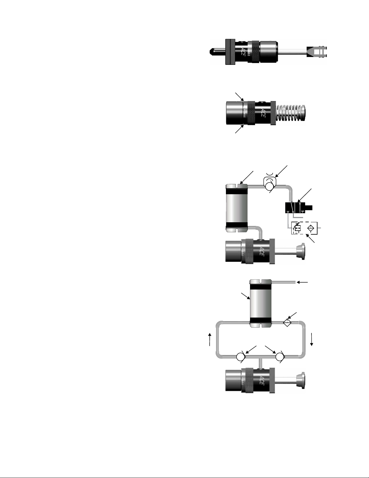
CLEVIS MOUNTING INSTALLATIION (Figure 4)
Fasten the rear clevis and the rod clevis to the mating
clevis members of the equipment. Make sure the shock
absorber is using the full stroke (less the last 3/32 inch
or 2.5 mm) and not being bottomed out. Be sure that the
equipment cannot pull the rod out any further than the
shock absorber stroke will allow.
ADJUSTMENT
Proper adjustment is important to the efficient operation
of the shock absorber. All units are pre-set at the factory.
Cycle the equipment to impact the shock absorber and
rotate the adjusting ring to achieve smooth deceleration.
Rotate towards zero to increase cushioning and away
from zero if the initial impact is too hard (Figure 5). If the
final setting approaches zero (less than 1), a larger shock
absorber should be considered. Tighten the adjusting ring
lock screw after achieving the final setting.
AIR EXHAUST CIRCUIT FOR MODEL AHS SHOCK
ABSORBERS
This type of installation (Figure 6) is necessary when it is
desired to have the rod remain in the shock absorber after
decelerating the load. Use special care to avoid overfilling
the air-oil tank. If not built in, a special ACE check valve
should be used to eliminate “misting” of oil out of the air-oil
tank.
RE-CIRCULATING COOLING CIRCUIT FOR MODELS
AHS & AHSS SHOCK ABSORBERS
This type of installation (Figure 7) may be required when
ambient temperatures and/or cycle rates cause the shock
absorber to head up beyond 200 F. Use high pressure
0
(1,000 psi) check valves with a low cracking pressure
(5 psi). If a filter is to be used in this circuit, a 30 to 40
micron filter element with a 5 psi by-pass is recommended.
Consult factory for assistance.
Figure 4
Figure 5
Less
Cushioning
9
0
More
Cushioning
Figure 6
Special ACE
Check Valve
Air-Oil Tank
3-Way Normally
Closed Valve
Sol
Exhaust
Supply
Filter/
Regulator
Figure 7
Air Supply
Air-Oil Tank
ACE Controls Inc.
World leader in deceleration technology
ISO 9001:2000 Certified
Optional Filter
High Pressure Check Valve
ACE Form 23,1-1/2” Adjustable
04/01/2004
 Loading...