

Page 1

Libretto Istruzioni
Instructions Booklet
Mode d’emploi
Bedienungsanleitung
Gebruiksaanwijzing
Libreto Instrucciónes
Strip-Cono
Page 2
○○○○○○○○○○○○○○○○○○○○○○○○○○○○○○○○○○○○○○○○○○○○○○○
UTILIZZAZIONE .................................................................................. 4
AVVERTENZE! ..................................................................................................... 4
ALLACCIAMENTO DEL CAVO DI ALIMENTAZIONE ALLA RETE .................................... 4
COMPONENTI ..................................................................................................... 4
INSTALLAZIONE ................................................................................. 5
FUNZIONAMENTO .............................................................................. 6
MANUTENZIONE ................................................................................ 6
INSTRUCTIONS FOR USE .................................................................... 7
WARNINGS! ........................................................................................................ 7
CONNECTION TO THE MAINS ................................................................................ 7
CONTENTS ......................................................................................................... 7
INSTALLATION ................................................................................... 8
OPERATION ....................................................................................... 9
MAINTENANCE ................................................................................ 10
UTILISATION .................................................................................... 11
ATTENTION! ...................................................................................................... 11
BRANCHEMENT DU CABLE D’ALIMENTATION AU RESEAU ..................................... 11
COMPOSANTS .................................................................................................. 11
ASSEMBLAGE .................................................................................. 12
FONCTIONNEMENT .......................................................................... 13
ENTRETIEN ..................................................................................... 13
BEDIENUNGSANLEITUNG .................................................................14
HINWEIS! ......................................................................................................... 14
NETZANSCHLUSS .............................................................................................. 14
ZUBEHÖR ......................................................................................................... 15
MONTAGEHINWEISE ........................................................................ 15
BETRIEB 16
WARTUNG 17
2
○○○○○○○○○○○○○○○○○○○○○○○○○○○○○○○○○○○○○○○
Page 3
○○○○○○○○○○○○○○○○○○○○○○○○○○○○○○○○○○○○○○○○○○○○○○○
GEBRUIK 18
AANWIJZINGEN! ............................................................................................... 18
ELEKTRISCHE AANSLUITING ............................................................................... 18
ONDERDELEN ................................................................................................... 18
INSTALLATIE .................................................................................... 19
WERKING 20
ONDERHOUD ................................................................................... 20
USO 21
ADVERTENCIAS! ................................................................................................ 21
CONEXIÓN DEL CABLE DE ALIMENTACIÓN A LA RED............................................. 21
COMPONENTES ................................................................................................. 21
INSTALACIÓN ..................................................................................22
FUNCIONAMIENTO ........................................................................... 23
MANTENIMIENTO ............................................................................23
○○○○○○○○○○○○○○○○○○○○○○○○○○○○○○○○○○○○○○○
3
Page 4
○○○○○○○○○○○○○○○○○○○○○○○○○○○○○○○○○○○○○○○○○○○○○○○
UTILIZZAZIONE
○○○○○○○○○○○○○○○○○○○○○○○○○○○○○○○○○○○○○○○○○○○○○○○
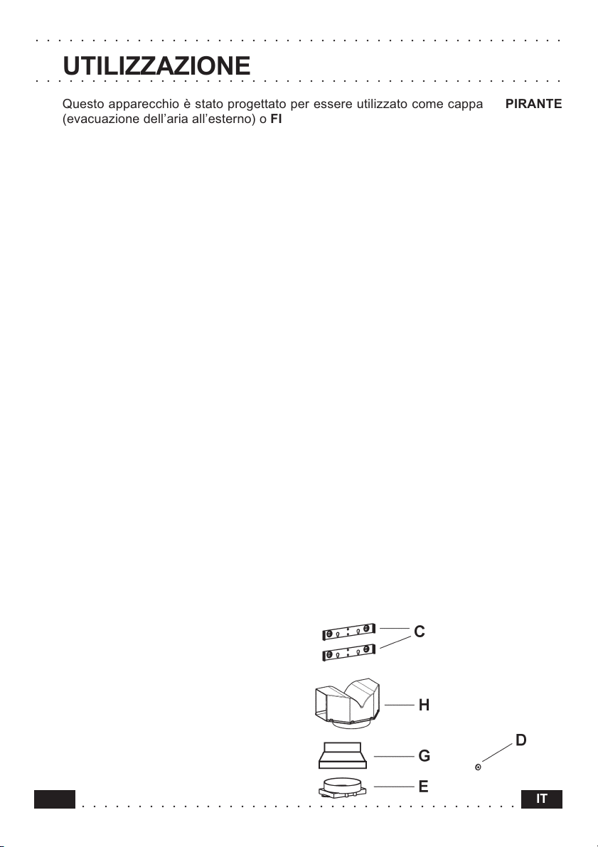
Questo apparecchio è stato progettato per essere utilizzato come cappa ASPIRANTE
(evacuazione dell’aria all’esterno) o FILTRANTE (riattivazione dell’aria all’interno).
AVVERTENZE!
- La distanza minima tra il piano di cottura e la parte inferiore della cappa deve essere
almeno di 650mm.
- Osservare le seguenti istruzioni riguardanti il funzionamento della cappa quando l’aria
viene convogliata verso l’esterno. (utilizzo aspirante)
- Deve essere prevista un’adeguata areazione del locale quando la cappa o apparecchi
alimentati con energia diversa da quella elettrica vengono usati contemporaneamente;
la pressione negativa della stanza non deve superare 4 Pa (4x10⁻⁵ bar).
- L’aria raccolta non deve essere convogliata in un condotto usato per lo scarico dei
fumi di apparecchi alimentati con energia diversa da quella elettrica.
- Rispettare le prescrizioni delle Autorità competenti relative allo scarico dell’aria da
evacuare.
- Evitare la presenza di fiamma libera nello spazio sottostante la cappa.
- La cappa è stata costruita con isolamento in Classe II pertanto non necessita di
connessione a terra.
- Prima di effettuare tutte le operazioni di manutenzione scollegare l’apparecchio dall’alimentazione elettrica.
ALLACCIAMENTO DEL CAVO DI ALIMENTAZIONE ALLA RETE
Prima dell’installazione verificare che la tensione della rete indicata sull’apposita targhetta
applicata all’interno dell’apparecchio, corrisponda alla tensione della vostra abitazione.
Montare sul cavo una spina normalizzata per il carico indicato sulla targhetta caratteristiche; nel caso di collegamento elettrico diretto alla rete è necessario interporre tra l’apparecchio e la rete un interruttore omnipolare con apertura minima tra i contatti di 3mm,
dimensionato al carico e rispondente alle norme in vigore.
Norme applicate:
EN 60335-1/88 (CEI 61-50/89) CEI EN 61000-3-2/95
EN 60335-2-31 (CEI 61-92/91) CEI EN 61000-3-3/95
CEI EN 55014/94 EN 55104/95
COMPONENTI
- 2 staffe di fissaggio C
- 1 rondella di fissaggio D
- 1 flangia di raccordo E
- 1 flangia di riduzione G
- 1 raccordo filtrante H
- 2 filtri al carbone attivo L (facoltativo)
4
○○○○○○○○○○○○○○○○○○○○○○○○○○○○○○○○○○○○○○○
IT
Page 5
○○○○○○○○○○○○○○○○○○○○○○○○○○○○○○○○○○○○○○○○○○○○○○○
INSTALLAZIONE
○○○○○○○○○○○○○○○○○○○○○○○○○○○○○○○○○○○○○○○○○○○○○○○
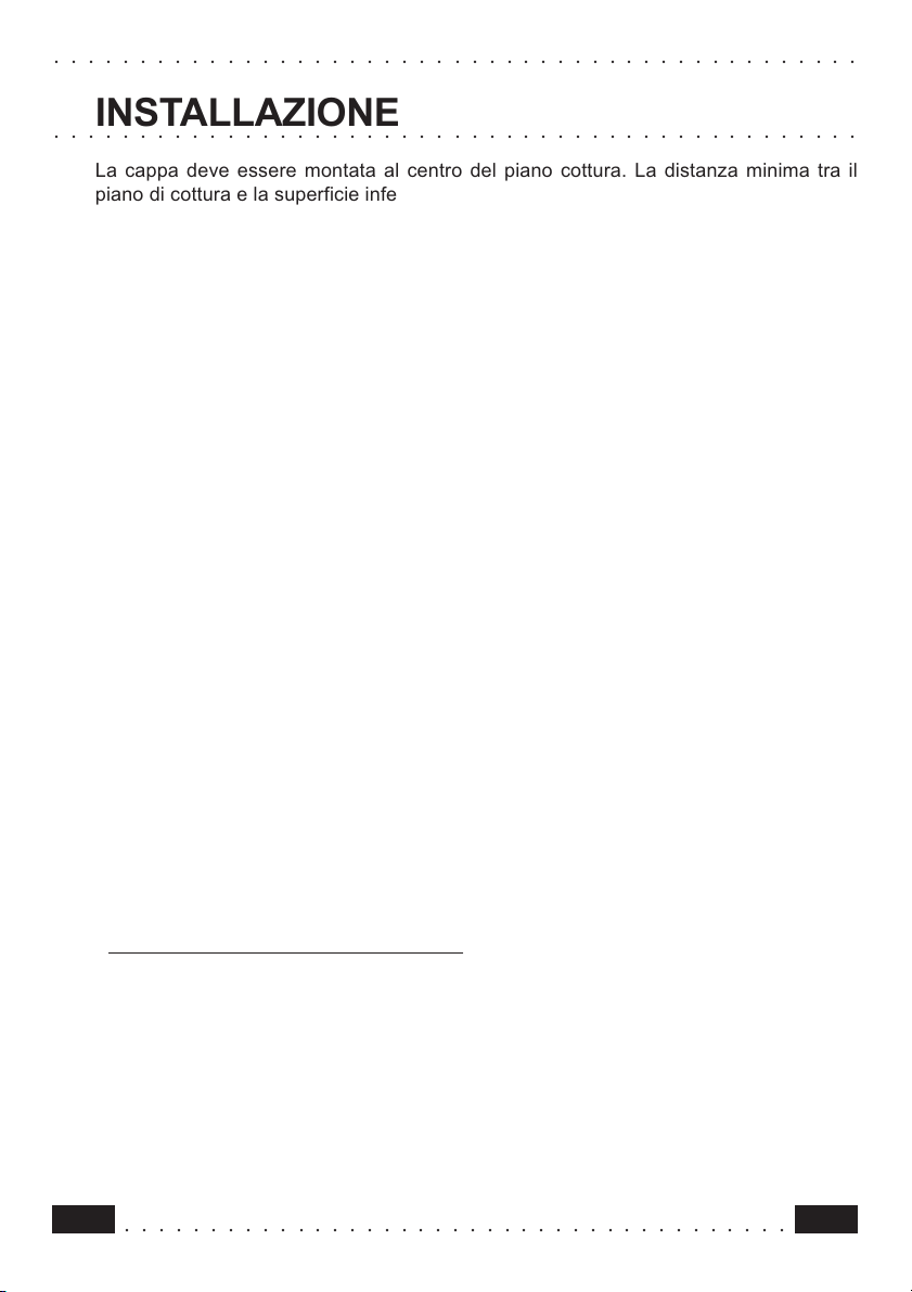
La cappa deve essere montata al centro del piano cottura. La distanza minima tra il
piano di cottura e la superficie inferiore della cappa deve essere di 650mm.
Per il montaggio della cappa procedere nel modo seguente:
1) Praticare n°8 fori (X1-X2-J-Y) Ø 8mm rispettando le quote indicate in fig. 1.
2) Per i vari montaggi utilizzare le viti e i tasselli espansione in dotazione.
3) Bloccare le staffe C (fig. 2) alla parete nei fori X1-X2.
4) Bloccare la rondella di fissaggio D (fig.2) alla parete nel foro Y.
NOTA: la parte scaricata della rondella deve essere rivolta verso la parete stessa.
5) Fissare la cappa alla parete nei fori esterni J1 e J2 (fig. 3) avendo cura che la rondella D
entri nell’asola posta sullo schienale della cappa.
6) Fissare la flangia di raccordo E con le apposite viti autofilettanti Ø 2,9mm alla bocca
uscita aria motore nei fori Z predisposti (fig. 4).
7) Montaggio ASPIRANTE o FILTRANTE:
7/A ASPIRANTE
Collegare con tubo F (non in dotazione) di Ø150mm (fig. 5), la flangia di raccordo E, e la
flangia di riduzione G allo scarico.
IMPORTANTE: Il tubo e gli eventuali gomiti di raccordo debbono innestarsi in quello
inferiore e non sovrapporsi. Per le operazioni di raccordo del tubo di scarico attenersi alle disposizioni vigenti nel Vostro Paese. L’aria evacuata non deve essere
inviata in un condotto utilizzato per evacuare i fumi degli apparecchi alimentati da
un’energia diversa da quella elettrica. Deve inoltre essere prevista una opportuna
ventilazione del locale se una cappa da cucina a apparecchi alimentati da una
energia diversa da quella elettrica evacuano i fumi contemporaneamente.
7/B FILTRANTE (Versione Opzionale)
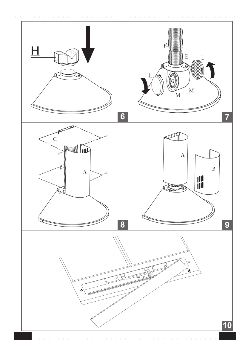
- Inserire il deflettore filtrante H (fig. 6).
- Montare i filtri carbone attivo L (fig. 7) centrando i medesimi nei supporti motore M e
bloccarli ruotando in senso orario (circa 10°) fino allo scatto di arresto. Per lo smontaggio
eseguire le operazioni all’inverso.
8) Fissare il camino lungo superiore A (fig. 8) alle staffe C (fig. 2/fig. 8) utilizzando n°4 viti
autofilettanti Ø2,9mm in dotazione. La distanza tra i fori di fissaggio X1 e X2 viene stabilita dall’altezza del camino superiore H1.
9) Applicare frontalmente il camino corto inferiore B (fig. 9) allargando leggermente le due
parti laterali e poi inserirlo nella cappa (fig. 9).
10) Sistema alternativo per fissaggio camini:
Alloggiare verticalmente nella cappa i camini A - B già inseriti uno dentro l’altro, sfilare il
camino superiore A fino alla staffa C e bloccarlo lateralmente alla medesima utilizzando
n° 2 viti autofilettanti Ø 2,9 mm in dotazione (fig. 8).
○○○○○○○○○○○○○○○○○○○○○○○○○○○○○○○○○○○○○○○
5IT
Page 6

○○○○○○○○○○○○○○○○○○○○○○○○○○○○○○○○○○○○○○○○○○○○○○○
FUNZIONAMENTO
○○○○○○○○○○○○○○○○○○○○○○○○○○○○○○○○○○○○○○○○○○○○○○○
Vi raccomandiamo di far funzionare l’apparecchio poco prima di procedere alla cottura di
qualsiasi vivanda e di lasciar funzionare lo stesso ancora per 15 minuti dopo la cottura,
comunque fintantochè ogni odore sia scomparso.
1) Quadro comandi con interruttori
- Un interruttore che comanda l’accensione dell’impianto di illuminazione.
- Un interruttore per commutare le tre velocità d’esercizio.
- Una generica spia di segnalazione motore in funzione.
2) Quadro comandi con pulsanti
- Un pulsante che comanda l’accensione del motore in prima velocità, adatta ad un
ricambiod’aria continuo particolarmente silenzioso, in presenza di pochi vapori di cottura.
- Un pulsante che comanda il motore in seconda velocità, adatta alla maggior parte delle
condizioni di uso, dato l’ottimo rapporto tra portata d’aria trattata e livello di rumorosità.
- Un pulsante che comanda il motore in terza velocità, adatta a fronteggiare le massime
emissioni di vapori di cottura, anche per tempi prolungati.
- Un pulsante che comanda l’accensione dell’impianto di illuminazione.
MANUTENZIONE
○○○○○○○○○○○○○○○○○○○○○○○○○○○○○○○○○○○○○○○○○○○○○○○
N.B. Prima di qualsiasi intervento di manutenzione, riparazione ed eventuale sostituzione lampade, disinserire l’apparecchio dalla rete elettrica.
1. Illuminazione
E’ costituita da due lampade da 40 W. Per effettuare una sostituzione operare come
segue (fig.10):
Togliere uno dei perni ai lati della plafoniera. Far scorrere il vetro verso il lato senza perno
fino a liberare la punta opposta, quindi tirare leggermente verso il basso. Sostituire le
lampade e rimontare il vetro con sequenza opposta.
2. Filtri
Ad intervalli più o meno frequenti, secondo l’uso della cappa, comunque una volta ogni 2
mesi, i filtri metallici debbono essere smontati e lavati con acqua calda saponosa, o
direttamente lavati in lavastoviglie e rimontati asciugati (i filtri in carbone attivo non
devono essere assolutamente lavati e devono essere sostituiti ogni 2 mesi).
3. Pulizia
Per la pulizia esterna della cappa utilizzare un panno umido con alcool o con prodotti
adatti reperibili in commercio. Evitate di usare degli elementi abrasivi.
IMPORTANTE: L’impiego di fiamma libera è dannoso ai filtri, pertanto è sconsigliato di
lasciare acceso un bruciatore a gas senza pentola. È obbligatorio mettere in atto le
operazioni di pulizia della cappa o dei filtri, nonchè la loro periodica sostituzione secondo le nostre istruzioni per evitare pericoli di incendio.
ATTENZIONE: La casa produttrice non risponde degli eventuali danni causati dalla mancata manutenzione del filtro antigrasso (lavaggio ogni due mesi), sostituzione del filtro
carbone ed il non rispetto delle istruzioni di montaggio ed allacciamento elettrico sopra
descritte.
6
○○○○○○○○○○○○○○○○○○○○○○○○○○○○○○○○○○○○○○○
IT
Page 7

○○○○○○○○○○○○○○○○○○○○○○○○○○○○○○○○○○○○○○○○○○○○○○○
INSTRUCTIONS FOR USE
○○○○○○○○○○○○○○○○○○○○○○○○○○○○○○○○○○○○○○○○○○○○○○○
This appliance has been designed for use as either an EXTRACTION (ducting to the
outside) or RECIRCULATION (filtering) hood.
The measurements contained on the drawings in this booklet refer to two models
of cooker hood. Therefore, it is essential that you refer to the correct drawing
when taking measurements for installation.
WARNINGS!
- The minimum distance between the cooking surface and the metal grease filters on the
underside of the hood must be 650mm.
- This cooker hood must be installed in accordance with the installation instructions
and all requirements must be adhered to.
- If the room where the cooker hood is to be used contains a fuel burning appliance
such as a central heating boiler then its flue must be of the room sealed or balance
flue type.
- If other types of flue or appliances are fitted ensure that there is an adequate supply
of air to the room.
- When the cooker hood is used in conjunction with appliances supplied with energy
other than electricity, the negative pressure in the room must not exceed 0.4 mbar to
prevent fumes being drawn back into the room by the hood.
- The ducting system for this appliance must not be connected to any ventilation system
which is being used for any other purpose.
- The ducting system for this appliance must not be connected to any existing ventilation
system which is being used for any other purpose.
- Do not leave naked flames or carry out flambe cooking under this cooker hood.
CONNECTION TO THE MAINS
WARNING: DOUBLE INSULATED DO NOT EARTH
Before connecting to the mains supply ensure the mains voltage corresponds to the
voltage on the rating plate inside the hood.
This appliance is fitted with a 2 core mains cable and must be permanently connected to
the electricity supply via a double-pole switch having 3mm minimum contact gap on
each pole.
Aplied norms:
EN 60355-1/88 (CEI 61-50/89) CEI EN 61000-3-2/95
EN 60335-2-31 (CEI 61-92/91) CEI EN 61000-3-3/95
CEI EN 55014/94 EN 55104/95
CONTENTS
- 2 No Wall Brackets C
- 1 No Locking Washer D
- 1 No Ducting Flange E
- 1 No 150-120mm Ducting Spigot G
- 1 No Air Deflector H
- 2 No Charcoal Filters L (Optional)
○○○○○○○○○○○○○○○○○○○○○○○○○○○○○○○○○○○○○○○
7GB
Page 8

○○○○○○○○○○○○○○○○○○○○○○○○○○○○○○○○○○○○○○○○○○○○○○○
INSTALLATION
○○○○○○○○○○○○○○○○○○○○○○○○○○○○○○○○○○○○○○○○○○○○○○○
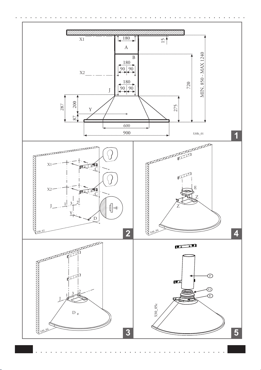
The cooker hood must be installed centrally over a cooking appliance. The minimum
distance between the cooking surface and the metal grease filters on the underside of
the hood must be at least 650mm. To install the hood proceed as follows: -
1 - Firstly, draw a vertical line approximately 950mm up the wall from the centre of the cooking
appliance. Secondly, draw two vertical lines 90mm either side of the first line up to the
ceiling. Thirdly, draw four horizontal lines through the vertical lines at Y-J-X2-X1 as
illustrated in fig. 1 to give you your drilling positions.
2 - Drill eight 8mm diameter holes at X1-X2-J-Y and insert the plastic rawl plugs supplied as
illustrated in fig. 2 ensuring the brackets are fitted as shown in the blow up.
3 - Secure the two brackets C to the wall inserting two of the screws supplied through the
two holes on line X1-X2 as illustrated in fig. 2.
4 - Secure the locking washer D to the wall inserting one of the screws supplied through
hole Y as illustrated in fig. 2 ensuring the washer is fitted with the recess to the wall
as shown in the blow up.
5 - Slide the canopy down the wall to locate the key hole over the washer then secure the
canopy to the wall by inserting two of the screws supplied through the two outer holes in
the rim of the canopy J1 and J2 as illustrated in fig. 3.
To prevent the canopy from accidentally being dislodged from the wall at anytime
fit the final screw supplied through hole J3.
6 - Fit the ducting flange E over the rectangular air outlet in the top of the canopy rim using
the two 2.9mm self tapping screws provided as illustrated in fig. 4.
7- EXTRACTION OR RECIRCULATION INSTALLATION:
7A EXTRACTION (Ducted)
- When used in the extraction(ducted) mode contaminated air enters the cooker hood
through the metal grease filters and passes out through ducting to the outside.
- When the hood is ducted to the outside the 150 to 120mm diameter ducting spigot G
must be fitted onto the ducting flange E as illustrated in fig. 5.
- The (optional) ducting required must be 120mm in diameter and made from fire retardent
material. Where flexible ducting is fitted it should not be turned through very tight bends
as this could impair the performance of the hood.
- IMPORTANT: The ducting used inside the chimney must not be larger than 120mm
in diameter as this could subsequently prevent the chimney fitting correctly.
- The ducting system for this appliance must not be connected to any ventilation
system which is being used for any other purpose.
7B RECIRCULATION (Filtered)
- When used in the recirculation mode (filtered) contaminated air enters the cooker hoDD
through the metal grease filters, passes through the (optional) cleansing charcoal filters
where it is purified and passes out into the kitchen through the grilles in the chimney.
- When the hood is fitted in the recirculation mode the air deflector H should be fitted as
illustrated in fig. 6.
- Fit the (optional) charcoal filters by repeating the following operation on each side of the
motor housing. Place the two key hole slots in the filter L over the tabs on the motor
housing M and turn the filter clockwise to lock the filter in position as illustrated in fig. 7.
8
○○○○○○○○○○○○○○○○○○○○○○○○○○○○○○○○○○○○○○○
GB
Page 9

○○○○○○○○○○○○○○○○○○○○○○○○○○○○○○○○○○○○○○○○○○○○○○○
- WARNING: It is a possible fire hazard if the metal grease filters are not cleaned and
the charcoal filters replaced regularly.
8 FITTING THE CHIMNEY
- To fit the (longer) upper chimney A, place the top edge of the chimney over the bracket C
as illustrated in fig. 8 and secure the chimney using two of the 2.9mm self tapping screws
provided.
- The distance in the height between the fixing holes X1 and X2 is determined by the
height of the upper chimney A.
- To fit the (shorter) lower chimney B, apply slight force to the two rear edges to increase
the width of the apperture, then sleeve the chimney B over the chimney A as illustrated
in fig. 9.
OPERATION
○○○○○○○○○○○○○○○○○○○○○○○○○○○○○○○○○○○○○○○○○○○○○○○
- The cooker hood functions are controlled by a series of slider or push button switches
mounted on the front of the hood and control the worktop lighting and fan motor speeds.
- This cooker hood will not remove steam.
1 - SLIDER SWITCHES
- A switch controls the wotktop lighting - ON/OFF.
- A switch controls the fan speeds - OFF/ON-1-2-3.
- The red neon lamp illuminates when the motor is switched ON .
2- PUSH BUTTON SWITCHES
- A switch controls the worktop lighting - ON/OFF.
- A button switches the motor OFF/ON at the low speed setting.
- A button switches the motor to the medium speed setting.
- A button switches the motor to the high speed setting.
- The red neon lamp illuminates when the motor is switched ON.
3- SPEED SETTINGS
- 1/Low should be selected when simmering or when using only one pan.
- 2/Medium should be selected for cooking when using up to four pans.
- 3/High should be selected when frying or cooking food with a strong odour.
○○○○○○○○○○○○○○○○○○○○○○○○○○○○○○○○○○○○○○○
9GB
Page 10
○○○○○○○○○○○○○○○○○○○○○○○○○○○○○○○○○○○○○○○○○○○○○○○
MAINTENANCE
○○○○○○○○○○○○○○○○○○○○○○○○○○○○○○○○○○○○○○○○○○○○○○○
N.B. Before carring out any kind of maintenance, cleaning or replacing lamps, disconnect
the hood from the mains supply.
1. Lighting
Comprises two 40W bulbs. To replace the bulbs, proceed as follows (fig.10): Remove
one of the pins at the sides of the lamp cover. Slide the glass towards the side from which
the pin has been removed until the opposite edge has been freed, then pull gently
downwards. Replace the bults and fit the glass again by repeating the above operations
in reverse order.
2. Filters
The metal grease filter should be cleaned every two months or more frequently if the
hood is used consistently and can be cleaned in a dishwasher or by hand using a mild
detergent or liquid soap. When replacing, ensure that they are dry.
The charcoal filter cannot be washed and should be replaced at least every 2 months or
more frequently if the hood is used consistently.
3. Cleaning
When cleaning the hood, it is recommended to use a damp cloth and mild liquid household
cleaner. Never use abrasive cleaning materials,
IMPORTANT: When using a gas hob in connection with the cooker hood never leave the
burners of the hob uncovered while the hood is in use or when the pans have been
removed. It is very important to follow all instructions for cleaning the hood and filters.
There could be a possible fire hazard if the filters are not replaced according to these
instructions.
ATTENTION: The manufacturer declines all responsibility for any damage or injury caused
as a result of not following the instructions for installation, for maintenance and replacement
times of filters indicated (in order to avoid a possible risk of fire when the filters are
saturated with grease).
10
○○○○○○○○○○○○○○○○○○○○○○○○○○○○○○○○○○○○○○○
GB
Page 11

○○○○○○○○○○○○○○○○○○○○○○○○○○○○○○○○○○○○○○○○○○○○○○○
H
L
L
M
H
6
8
7
9
○○○○○○○○○○○○○○○○○○○○○○○○○○○○○○○○○○○○○○○
10
25
Page 12
○○○○○○○○○○○○○○○○○○○○○○○○○○○○○○○○○○○○○○○○○○○○○○○
S30_05c
F
E
G
1
2
3
26
○○○○○○○○○○○○○○○○○○○○○○○○○○○○○○○○○○○○○○○
4
5
Page 13
○○○○○○○○○○○○○○○○○○○○○○○○○○○○○○○○○○○○○○○○○○○○○○○
6
8
7
9
○○○○○○○○○○○○○○○○○○○○○○○○○○○○○○○○○○○○○○○
10
27
Page 14

Quest’apparecchio é conforme alla norma europea sulla bassa tensione C.E.E. 73/23 relativa
alla sicurezza elettrica e alle norme europee: C.E.E. 89/336 relativa alla compatibilità elettromagnetica e C.E.E. 93/68 relativa alla marcatura CE.
This appliance complies with European regulations on low voltages, EEC Directive 73/23 on
electrical safety, and with the following European regulations: EEC Directive 89/336 on
electromagnetic compatibility and EEC Directive 93/68 on EC marking.
Cet équipement est conforme à la norme européenne sur la basse tension C.E.E. 73/23
relative à la sécurité électrique et aux normes européennes: C.E.E. 89/336 relative à la
compatibilité électromagnétique et C.E.E. 93/68 relative au marquage CE.
Dieses Gerät entspricht den europäischen Niederspannungsrichtlinien 73/23/EWG zur
elektrischen Sicherheit, den europäischen Richtlinien 89/336/EWG zur elektromagnetischen
Verträglichkeit und den Richtlinien 93/68/EWG zur CE-Kennzeichnung
Dit apparaat voldoet aan de Europese Laagspanningsrichtlijn 72/23/EEG inzake de elektrische
veiligheid en aan de Europese normen 89/336/EEG inzake de elektromagnetische
compatibiliteit en 93/68/EEG inzake de CE-markering.
Este aparato respeta la norma europea de baja tensión C.E.E. 73/23 que hace referencia a la
seguridad eléctrica y a las normas europeas: C.E.E. 89/336 relativa a la compatibilidad
electromagnética y C.E.E. 93/68 relativa a la marca CE.
4329252 11 - 011017
 Loading...