

Page 1

STEAM ‘N’ HOLD
STEAMER
OWNERS MANUAL
IMPORTANT WARRANTY INFORMATION:
For product warranty activation, the Product Registration Form must be submitted to
AccuTemp Products, Inc. after installation of the appliance.
Product Registration Form
AT1T-2739-1 Rev. A
STEAM ’N’ HOLD
STEAMER OWNERS MANUAL
Page i
Page 2

TABLE OF CONTENTS
DOCUMENT HISTORY ii
TABLE OF CONTENTS ii
SAFETY WARNINGS 1 – 2
INSTALLATION 3 – 5
INITIAL START-UP 6 – 8
OPERATION 7 – 10
DAILY CLEANING 11
SERVICE AND TROUBLESHOOTING 12 – 14
6 PAN STEAMER ELECTRICAL SCHEMATICS 15 – 20
3 PAN STEAMER ELECTRICAL SCHEMATICS 21 - 29
WARRANTY 30
DOCUMENT HISTORY
Current revision: A Prior revision: Date: 8/24/06 Date: None
Change
Initial release - 6/26/07.
_____________________________________________________________
__________
AT1T-2739-1 Rev. A
STEAM ’N’ HOLD
STEAMER OWNERS MANUAL
Page ii
Page 3
SAFETY WARNINGS
DANGER:
CAUTION:
location.
W
ARNING:
Never use wet or damp gloves, as moisture can conduct heat quickly
! !!
1. Only personnel qualified to work with electricity should install this
unit. Improper installation can cause personal injury or damage to
the equipment.
2. This appliance must be properly grounded. Failure to properly
ground the appliance could result in electrocution and/or death.
1. When using a stand that is equipped with casters, the floor surface
must
be level and flat. Failure to do so can result in a “tipping”
situation and could result in serious injury.
2. Direct contact with steam can result in a severe burn.
3. When accessing the cooking chamber, be sure to always stand back
while slowly opening the door, allowing the chamber to vent its
steam. Never look or reach into the cooking chamber before it has
completely vented its steam.
4. Never reach into the cooking chamber or handle hot items without
wearing proper hot gloves.
5.
and could result in a severe burn.
1. Be sure all operators read, understand and follow the information
contained in this manual, including caution warnings, operating
instructions, and safety instructions.
2. Use caution when operating the steamer. Direct contact with steam
can result in a severe burn.
3. Please use caution when emptying the drip pan. The pan’s contents
could cause severe burns.
4. Keep the floor in front of the equipment clean and dry. If spills occur,
clean immediately to avoid the potential injuries.
5. Do not use pressurized water to clean steamer.
6. Use of any replacement parts other then those supplied by AccuTemp
Products, Inc. can cause bodily injury to the operator, damage to the
equipment and will void all warranties.
7. This appliance is extremely heavy. For safe handling, the installer
should obtain help as needed or employ appropriate material handling
equipment to remove unit from it’s packaging and move it into its final
AT1T-2739-1 Rev. A
STEAM ’N’ HOLD
STEAMER OWNERS MANUAL
Page 1 / 32
Page 4
SAFETY WARNINGS (cont.)
IMPORTANT:
IMPORTANT SERVIC
E INFORMATION
CAUTION (cont.):
! !
8. Do not use the low water warning indicator and buzzer as substitutes
for checking the water level in the cooking chamber periodically.
Failure to properly maintain the water level may result in improperly
cooked product and over time, may result in a premature service issue
that may not be covered under warranty.
1. Never leave a de-liming agent in contact with the stainless steel
longer than 10 minutes before rinsing the cooking chamber
thoroughly with water. Longer contact can cause corrosion.
2. Do not use abrasive materials, such as wire brushes, metal scouring
pads or scrapers to clean the cooking chamber bottom.
3. Service must be performed only by AccuTemp Products, Inc.
authorized service personnel. Service performed by unauthorized
personnel will void all warranties.
4. Any in-field modification made without written authorization from
AccuTemp will void the warranty.
An AccuTemp Products, Inc. Technical & Customer Support Technician is
AT1T-2739-1 Rev. A
1-800-480-0415 or +1-260-469-3040
available Monday thru Sunday, 7:00am to 7:00pm EST.
STEAM ’N’ HOLD
STEAMER OWNERS MANUAL
Page 2 / 32
Page 5

INSTALLATION
BUILDING CODES AND STANDARDS
The steamer must be installed in accordance with the following building codes:
USA: National Electric Code, ANSI/NFPA-70, state and local codes.
Canada: Canadian Electric Code, CSA C22.2 and local codes.
UNPACKING
This steamer was inspected before shipment from the factory. The shipping
company accepts full responsibility for safe delivery. Immediately after unpacking,
check the steamer for possible shipping damage. If damage is identified, saving the
packaging material and contact the shipping carrier within 15 days.
LOCATION AND PLACEMENT
To insure maximum benefit of your warranty; location, placement and leveling are
critical. The AccuTemp Steam ‘N’ Hold steamer is designed for installation on either a
commercial kitchen countertop or an AccuTemp Steam ‘N’ Hold stand.
Your Steam ‘N’ Hold steamer is equipped with vents to allow the proper ventilation
of air through the electrical compartments. On current S6 & S3 Steam ‘N’ Hold models,
the vents are located on the bottom and rear panels. To ensure these vents work
properly, a minimum 4 inch (102 mm) clearance from these vents must be allocated.
It is also recommended that the Steam ‘N’ Hold not be placed under other wet
equipment or locations.
Note:
rear face and left side panels. A minimum spacing of 6 inches (152 mm) to the left side
access panel is required between heat sources such as, but not limited too, a range,
griddle or fryer. A minimum spacing of 3 inches (76 mm) to the rear face, between any
object such as a wall, barrier or other piece of equipment, must be allocated as well.
LEVELING
The steamer must be installed in a level condition. An out-of-level condition may
cause improper operation and possible damage. Damage caused by improper leveling
is not covered by warranty. Use a spirit level, resting on the top steamer cabinet
surface, to ensure it is level front-to-back and left-to-right.
If this is a counter-top installation, be sure to install a rubber foot tip
provided with your steamer onto the foot adjuster of each of the steamer leg
as shown. This will keep the steamer from sliding on the counter-top under normal
use. Once the rubber foot tips have been installed, rotate the foot adjusters up or
down as needed to level the steamer.
For S6 models with a serial number lower than 22627, vents are located on the
AT1T-2739-1 Rev. A
STEAM ’N’ HOLD
STEAMER OWNERS MANUAL
Page 3 / 32
Page 6

INSTALLATION (cont.)
!!
SINGLE STEAMER STAND INSTALLATION
The AccuTemp SNH10 single stand is equipped with adjustable height feet and the
AccuTemp SNH11 single stand is equipped with non-adjustable height casters. Both
can be used with either a one S6 or S3 model Steam ‘N’ Hold steamer. Before
mounting a steamer on the SNH11 stand, engage the brakes on the two front locking
casters, pressing on the “ON” handle of the brake mechanism. To mount the steamer,
carefully lift and place it on the horizontal mounting brackets, ensuring that the (4)
mounting holes on the underside of the Steam ‘N’ Hold are lined up with the mounting
holes on the brackets. Then, using a 7/16” wrench, fasten one pair of the 1/4"-20 hex
bolts and 1/4" split lock washers through the underside of each stand bracket mounting
hole into the Steam ‘N’ Hold and tighten securely.
steamer by adjusting the feet found at the ends of each stand leg, either up or down as
needed.
WARNING
When using a stand that is equipped with casters, the floor surface must be
level and flat. Failure to do so can result in a “tipping” situation that could
result in serious injury.
DOUBLE STEAMER STAND INSTALLATION
The AccuTemp SNH20 double stand is equipped with adjustable height feet and the
AccuTemp SNH21 double stand is equipped with non-adjustable height casters. Both
stands can accommodate either two S6 model Steam ‘N’ Holds, two S3 Model Steam ‘N’
Holds or a one of each steamer model. When ordered as a steamer set, one of the two
steamers will be designated as a “bottom unit” on the outside of its packaging. Before
mounting a steamer on the SNH21 stand, engage the brakes on the two front locking
casters, pressing on the “ON” handle of the brake mechanism. To mount the steamer,
carefully lift and place it on the horizontal mounting brackets, ensuring that the (4)
mounting holes on the underside of the Steam ‘N’ Hold are lined up with the mounting
holes on the brackets. Then, using a 7/16” wrench, fasten one pair of the 1/4"-20 hex
bolts and 1/4" split lock washers through the underside of each stand bracket mounting
hole into the Steam ‘N’ Hold and tighten securely.
Once the “bottom unit” has been installed, carefully lift and place the “top unit”
Steam ‘N’ Hold steamer on the horizontal mounting brackets, ensuring that the (4)
mounting holes on the underside of the Steam ‘N’ Hold are lined up with the mounting
holes on the brackets. Then, using a 7/16” wrench, fasten one pair of the 1/4"-20 hex
bolts and 1/4" split lock washers through the underside of each stand bracket mounting
hole and tighten securely.
With the SNH20 stand, level the steamers by adjusting the feet found at the ends of
each stand leg, either up or down as needed.
With the SNH10 stand, level the
AT1T-2739-1 Rev. A
STEAM ’N’ HOLD
STEAMER OWNERS MANUAL
Page 4 / 32
Page 7

INSTALLATION (cont.)
WARNING
When using a stand that is equipped with casters, the floor surface must be
level and flat. Failure to do so can result in a “tipping” situation that could
result in serious injury.
ELECTRICAL SUPPLY
The AccuTemp Steam ‘N’ Hold steamer has been designed, manufactured and
tested to meet or exceed the Underwriters Laboratories safety standards. To ensure
safety is maintained in your installation, it is important that the following paragraphs
are understood before attempting to apply power to your Steam ‘N’ Hold. If there is
any doubt as to whether your supply receptacle is of the correct voltage, amperage, or
is properly grounded, consult a qualified electrician or serviceman.
POWER REQUIREMENTS
AC power requirements are listed on the data plate located on the left side access
panel on all steamers. Steamers should never be connected to a circuit operating at
more than 150 VAC to ground and should always be connected to an individual branch
circuit. Make sure the voltage at the supply receptacle is within ±10% of the voltage
listed on the steamer’s data plate. Connection to any other voltage may permanently
damage your Steam ‘N’ Hold or cause premature component failure. Damage of this
type is not covered under the product warranty. Each Steam ‘N’ Hold steamer comes
equipped with a connected 6 foot power cord and plug, rated for the power
requirements of each steamer. Damage caused by removal or modification of factory
standard plug is not covered by product warranty.
GROUNDING
To reduce the risk of serious shock or death in the event of an electrical short
circuit, this appliance must be grounded. The Steam ‘N’ Hold steamer is equipped with
a cord having a grounding wire and plug, which must be plugged into a receptacle that
is properly installed and grounded. Under no circumstance should the grounding plug
be cut or bent to fit a receptacle other than the one specified.
DRAIN CONNECTION
While there are no AccuTemp-supplied drain components, some customers may
desire to construct a drain connection. Any drain connections must include an air gap
between the steamer and the drain to avoid creating a back siphon effect into the
steamer cooking compartment.
HOOD VENTILATION
Some local building codes may require the steamer to be located under an exhaust
hood. Please check local building code requirements before completing installation of
the steamer.
AT1T-2739-1 Rev. A
STEAM ’N’ HOLD
STEAMER OWNERS MANUAL
Page 5 / 32
Page 8
INITIAL START-UP
!
INTRODUCTION
The AccuTemp Steam ‘N’ Hold steamer takes the time-proven method of cooking
with steam and adds the advantage of control. This is accomplished by reducing the
internal atmospheric pressure of the Steam ‘N’ Hold cooking chamber, thereby lowering
the temperature at which the water begins to boil. This allows the operator to control
the temperature of the steam for cooking. Controlling the steam temperature gives the
operator the ability to cook the food to the desired temperature without over-cooking,
resulting in a more tender, juicier, nutritious product and with less shrinkage than was
previously possible. Once the cooking time expires, the steamer automatically enters
the “Hold” mode. In this mode, the thermostat regulates the internal temperature, but
vacuum is released, returning the cooking chamber to normal atmospheric pressure. At
this time, steam is no longer generated and the cooking chamber is held at the desired
temperature at a relative humidity of 100%. This eliminates food from drying out by
suppressing the evaporation of the products’ natural moisture. As a result, most food
products can be held in a ready-to-serve state for several hours after cooking, with no
appreciable loss in taste, appearance or consistency.
DAILY PREPARATION FOR USE
Preparing the Steam ‘N’ Hold for use each day requires very little time and effort:
simply fill the steamer with water and preheat.
Caution
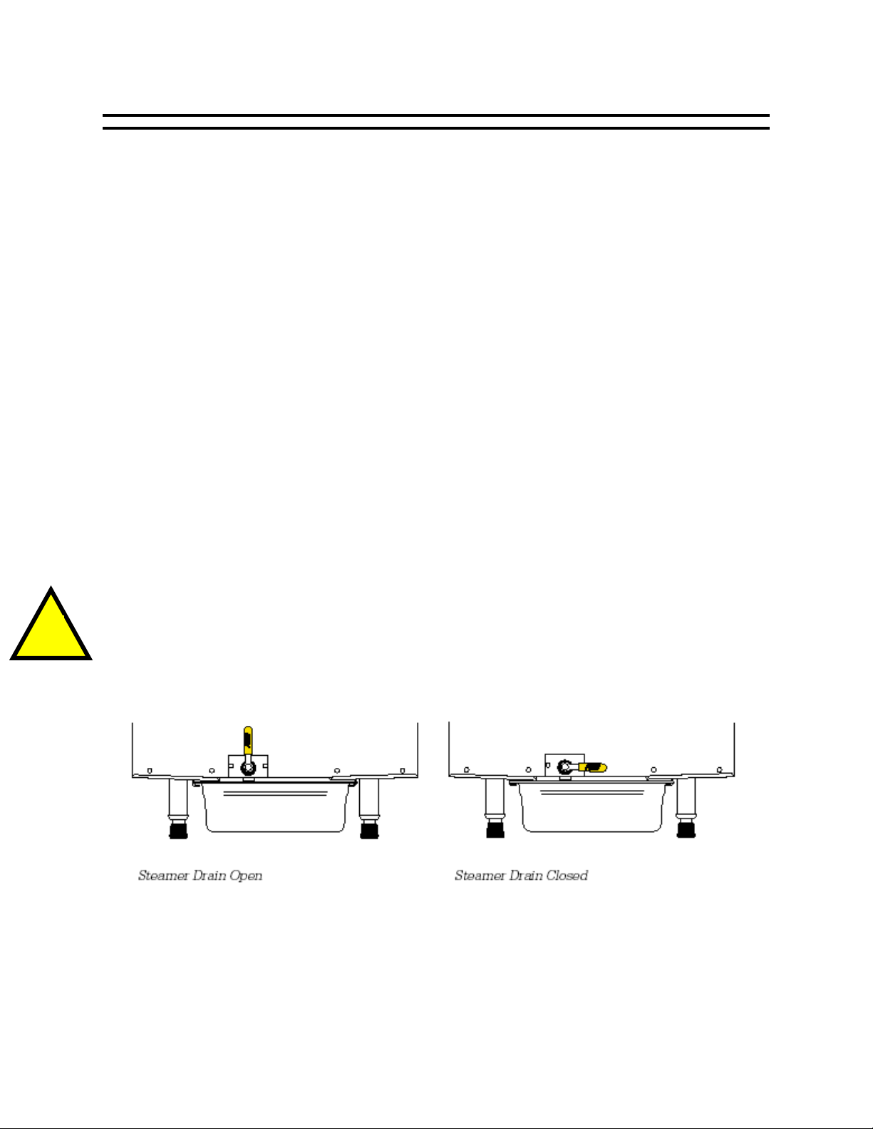
Before filling the cooking chamber with water, ensure that the drain valve on
the front of the Steam ‘N’ Hold is in the closed position. Ensure that a full
size steam table pan or a 1/1 gastronome pan with a minimum depth of 4
inches, has been positioned on the pan rail brackets under the steamer.
At the beginning of each day, open the door of the Steam ‘N’ Hold and pour 3
gallons (11 liters) of ordinary tap water into the bottom of the cooking chamber.
(Although the mineral content of the water is not that important, the Steam ‘N’ Hold
should always be drained and cleaned at the end of each day to prevent food or
mineral buildup.)
AT1T-2739-1 Rev. A
STEAM ’N’ HOLD
STEAMER OWNERS MANUAL
Page 6 / 32
Page 9

INITIAL START-UP (cont.)
!
Daily water usage will depend on several factors: cooking temperature, the
products being cooked and the length of time the door is open. In most cases, 3
gallons (11 liters) of water will last several hours or more. However, the level of the
water should be checked periodically to avoid running low and or out. If the Steam ‘N’
Hold does run out of water, the “Low Water” warning indicator light and buzzer will turn
on. Should this occur, simply turn the Steam ‘N’ Hold off, refill it with water and restart
the unit. If the shutdown occurred during cooking, the cycle will resume at the point it
stopped. However, a time adjustment may be necessary, depending on the
temperature of the water the steamer was re-filled with.
CAUTION
Do not use the low water warning indicator light and buzzer as substitutes
for checking the water level in the cooking chamber periodically. Failure to
properly maintain the water level may result in improperly cooked product
and over time may result in a premature service issue that may not be
covered under warranty.
AUTO-FILL MODELS
The Steamer must be connected to the facility water supply via an appliance hose,
preferably a stainless steel braided hose with a ¾” garden hose type connection, from
a water spigot or from a nearby sink faucet.
First time fill (the Steamer water reservoir is empty of water):
1. With the water supply turned on, press the “ON” button. The Steamer will
power up with the pump operating.
2. Both water valves will be turned on.
3. A relay will bypass the low water level sensing to allow for first time filling of the
reservoir.
4. The thermostat will be turned off for the first fill to prevent damage to the heater
elements.
5. Water will rise to the low level probe and reset the low level circuit of the water
control board.
6. The water will continue to rise until it contacts the High Level Probe.
7. A five second delay is initiated when the water touches the High-level probe to
allow for wave action in side the water reservoir.
lower than desired amount of water to be injected in the reservoir by tripping the
control too soon if there were no sequence to ignore the wave action inside the
reservoir.
8. When the five seconds has been satisfied the water level control board shuts off
the water level control relay and the by pass relay.
9. The heater is turned on and normal operation begins.
Wave action would cause a
AT1T-2739-1 Rev. A
STEAM ’N’ HOLD
STEAMER OWNERS MANUAL
Page 7 / 32
Page 10

INITIAL START-UP (cont.)
PREHEATING
To maximize efficiency, while minimizing cook time, it is always recommended to
preheat the cooking chamber prior to cooking.
S6 Model: With the water reservoir full, close the door, set the thermostat to the
desired cooking temperature, position the toggle switch to the “Thermostat” mode
[160°F (71°C) – 200°F (93°C)] or the “Fast Cook” mode (212°F/100°C), set timer to 15
minutes and press the “ON” button. When the pre-heat cycle is complete, the steamer
will automatically switch to the “Hold” mode, at which time the Steam ‘N’ Hold is ready
for use. Please note, when steamer is in “Hold” mode, the thermostat setting will
regulate the cooking chamber temperature even if the steamer is set in the “Fast Cook”
mode.
S3 Model: With the water reservoir full, close the door, set the thermostat to the
desired cooking temperature, set timer to 15 minutes, turn the rotary selector switch to
“ON” and then select either “Cook” [160°F (71°C) – 200°F (93°C)] or “Fast Cook”
(212°F/100°C). When cycle is complete, the steamer will automatically switch to “Hold”
mode at which time the Steam ‘N’ Hold is ready for use. Please note, when steamer is
in “Hold” mode, the thermostat setting will regulate the cooking chamber temperature
even if the steamer is set in the “Fast Cook” mode.
AT1T-2739-1 Rev. A
STEAM ’N’ HOLD
STEAMER OWNERS MANUAL
Page 8 / 32
Page 11

OPERATION
! !
COOKING
Low Temperature Cooking [160°F (71°C) – 200°F (93°C)]
Did you know that with the AccuTemp Steam ‘N’ Hold steamer, you could
cook and hold food all at the same time? With its patented vacuum cooking
technology, the Steam ‘N’ Hold offers you the versatility of cooking and
holding different types of food product all at the same time when cooking
with low temperature steam.
S6 Model: To begin low temperature cooking, position the toggle switch into
“Thermostat” mode, set the thermostat to the desired cooking temperature, set the
timer to the desired cooking time and press the “ON” button, if the steamer has to be
started.
CAUTION
Maximum recommended food load for the S6 model is 100lbs (45Kg).
S3 Model: To begin low temperature cooking, set the thermostat to the desired
cooking temperature, set the timer to the desired cooking time and turn the selector
switch to “ON”, if the steamer has to be started, and then select “Cook”.
CAUTION
Maximum recommended food load for the S3 model is 50lbs (23Kg).
Try using perforated pans for the best results in cooking! By allowing
steam to penetrate from all directions, perforated pans will maximize heat
transfer and give you the shortest cooking times.
High Temperature Cooking (212°F/100°C)
S6 Model: To begin high temperature cooking, position the toggle switch to “Fast
Cook”, set the timer to the desired cooking time and press the “ON” button, if the
steamer has to be started.
S3 Model: To begin high temperature cooking, set the timer to desired cooking time,
and turn the selector switch to “ON”, if the steamer has to be started, and then select
“Fast Cook”.
AT1T-2739-1 Rev. A
STEAM ’N’ HOLD
STEAMER OWNERS MANUAL
Page 9 / 32
Page 12

OPERATION (cont.)
Continuous Cook
This feature gives you the flexibility of cooking independently of the cooking timer
and can be utilized in either low temperature or high temperature cooking.
S6 & S3 Model: Follow either low temperature or high temperature cooking
guidelines but instead of selecting a time period, rotate the timer knob clockwise until
the white indicator on the timer knob lines up with the yellow “Continuous” position.
Note:
On S6 units with a serial number less than 22627, rotate the timer knob
clockwise until the timer knob rests against the timer “stop pin”.
Checking Food While Cooking
To maximize efficiency, while minimizing cooking time, it is always recommended to
allow food to finish it’s cook cycle before opening the cooking chamber door. However,
if the door is opened during a cooking cycle, a time adjustment may be necessary,
depending on how long and often the chamber door was opened.
S6 Model: Press the “OFF” button, stand back while slowly opening the door, allowing
the cooking chamber to vent its steam. Once steam has vented, carefully check the
food, close the door and press the “ON” button to continue cooking.
S3 Model: Press the “OFF” button, stand back while slowly opening the door, allowing
the cooking chamber to vent its steam. Once steam has vented, carefully check the
food, close the door and turn the selector switch to “ON” and “Cook” or “Fast Cook” to
continue cooking.
HOLDING
The Steam ‘N’ Hold will automatically enter the “Hold” mode once timer cooking
time has expired, where the buzzer will sound, alerting the operator that the food is
ready. A slight counterclockwise manual adjustment to the “Hold” position on the timer
knob is needed to turn off the buzzer. The “Hold” temperature is determined by the
thermostat setting. It is recommended to preheat the cooking chamber to the desired
holding temperature if the cooking chamber is in a cool state.
S6 Model: To hold food independently of cooking, rotate the timer counter clockwise
until the white indicator on the timer knob lines up with the yellow “Hold” position.
Select desired the “Hold” temperature and press the “ON” button.
S3 Model: To hold food independently of cooking, rotate the timer counter clockwise
until the white indicator on the timer knob lines up with the yellow “Hold” position.
Select desired the “Hold” temperature and turn the selector switch to “ON” and “Cook”
or “Fast Cook”.
Note:
On S6 units with a serial number less than 22627, rotate the timer knob
clockwise until the timer knob rests against the timer “stop pin”.
AT1T-2739-1 Rev. A
STEAM ’N’ HOLD
STEAMER OWNERS MANUAL
Page 10 / 32
Page 13

DAILY AND WEEKLY CLEANING
!
DAILY CLEANING
At the end of each day, the Steam ‘N’ Hold should be drained and cleaned.
1) Turn the steamer off.
2) Allow the cooking chamber water to cool. Ensure that a full size steam table pan or
a 1/1 gastronome pan with a minimum depth of 4 inches (101 mm) has been placed
beneath the Steam ‘N’ Hold. Use caution while opening the drain valve. Empty the
water into the drain pan and discard the water.
3) Dry the inside of the cooking chamber, including the two low water sensors, with a
cloth. Failure to follow this cleaning procedure can result in inefficient cooking and
false low water readings with the low water sensors that will shut the steamer down
even though there may be plenty of water in the reservoir.
4)
Do not use a water jet to clean steamer.
5) Leave the door open to allow the cooking chamber to dry overnight.
WEEKLY CLEANING
Once a week, the Steam ‘N’ Hold should be drained and cleaned more thoroughly than
the daily cleaning.
1) Fill the cooking chamber with 2 gallons (7.6 liters) of water and one cup (8 ounces
or 0.24 liters) of white vinegar.
2) Turn the Steamer on and operate for 30 minutes at the maximum temperature in
the THERMOSTAT mode (200ºF/93ºC) or set the Switch to the FAST COOK position.
3) Allow the water and vinegar mixture to cool. Ensure that a full size steam table pan
or a 1/1 gastronome pan with a minimum depth of 4 inches (101 mm) has been
placed beneath the Steam ‘N’ Hold. Use caution while opening the drain valve.
Empty the water into the drain pan and discard the water.
4) Rinse the cooking chamber thoroughly with water. Empty the water and vinegar
mixture into the drain pan and discard the mixture.
5) Remove the pan rails. Dry the inside of the cooking chamber, the two low water
sensors and the pan rails with a cloth. Failure to follow these cleaning procedures
can result in inefficient cooking and false low water readings with the low water
sensors that will shut the steamer down even though there may be plenty of water
in the reservoir.
6) Leave the door open to allow the cooking chamber to dry overnight.
AT1T-2739-1 Rev. A
STEAM ’N’ HOLD
STEAMER OWNERS MANUAL
Page 11 / 32
Page 14

SERVICE AND TROUBLESHOOTING
0415 or
To prevent electrical shock, do not open covers. There are no us
er serviceable
IMPORTANT SERVICE INFORMATION
Service must be performed only by AccuTemp Products, Inc. authorized
service personnel. Service performed by unauthorized personnel will void all
Call AccuTemp Products, Inc. Technical Service Hotline at 1-800-480-
Both high and low voltages are present inside this equipment, even when
turned off. Remove the equipment from all power sources prior to servicing.
An AccuTemp Products, Inc. Technical & Customer Support
Technician is available Monday thru Sunday, 7:00am to 7:00pm EST.
+1-260-469-3040 for the nearest service agent.
WARNING
warranties.
parts inside.
1-800-480-0415 or +1-260-469-3040
GENERAL SERVICE INFORMATION
Conventional steamers require scheduled service (such as boiler maintenance) at
relatively frequent intervals. The Steam ‘N’ Hold steamer however, requires no such
requirements due to its unique design.
Because the Steam ‘N’ Hold has been engineered for the highest reliability, most
problems that arise can be attributed to minor oversights, such an incorrect
temperature or failure to close door securely. These types of situations are addressed in
the following paragraphs.
To ensure continued safe and reliable operation of your Steam ‘N’ Hold, only Factory
Authorized Service Personal should perform any component replacement or major
repair. Please contact the AccuTemp Technical Service Department for help at 800-4800415 or 260-469-3040 if the measures described below fail to correct your problem.
BASIC TROUBLESHOOTING
Steam Will Not Turn On
• Make sure the unit is plugged in (if applicable).
• Check the facility circuit breaker (or fuses) supplying the unit.
• Call AccuTemp Products, Inc. Technical Service toll free at 1-800-480-0415 or at
+1-260-469-3040.
AT1T-2739-1 Rev. A
STEAM ’N’ HOLD
STEAMER OWNERS MANUAL
Page 12 / 32
Page 15

SERVICE AND TROUBLESHOOTING (cont.)
Steamer displays “Low-Water”
• Check level of water in cooking chamber and add accordingly.
• If cooking chamber is full (3 gallons/11 liters), water sensors may have a film
across them. Clean sensors by draining unit of water and wiping sensors off with
a towel and mild detergent and then rinse thoroughly.
• Call AccuTemp Products, Inc. Technical Service toll free at 1-800-480-0415 or at
+1-260-469-3040.
Food Is Over Cooked
• Check that the proper cook temperature is being used. (Excess time will cause
over-cooking only when the temperature setting is moderately higher than the
desired final product temperature).
• Call AccuTemp Products, Inc. Technical Service toll free at 1-800-480-0415 or at
+1-260-469-3040.
Food Is Under Cooked
• Make sure you are using adequate time and temperature settings. Extra time
may be required if pans are covered or if product is left in plastic bags or similar
packaging.
• Try distributing the product more evenly within the steamer and or pans, if
possible.
• Make sure the water drain valve on the front of the Steam ‘N’ Hold is tightly
closed. The steamer may appear to be cooking normally if the valve is slightly
open but efficiency may be compromised.
• Check the door seal for food debris. Food debris on the face of the door seal or
under flap may cause steamer to appear to be cooking normally but efficiency
may be compromised. Nicks or cuts in the door seal may also cause inefficient
cooking.
• Call AccuTemp Products, Inc. Technical Service toll free at 1-800-480-0415 or at
+1-260-469-3040.
Low Vacuum Gauge Readings
• The higher the temperature setting, the lower the vacuum gauge reading. When
operating at 212° (Fast Cook), the gauge will read near or at zero.
• Verify that the door has been closed securely.
• Check to make sure there is no food debris on the face of the door seal or
behind its flap. Also check the door seal for damage such as nicks or cuts.
• Call AccuTemp Products, Inc. Technical Service toll free at 1-800-480-0415 or at
+1-260-469-3040.
AT1T-2739-1 Rev. A
STEAM ’N’ HOLD
STEAMER OWNERS MANUAL
Page 13 / 32
Page 16

SERVICE AND TROUBLESHOOTING (cont.)
Unit Will Not Turn Off
• This symptom, which is extremely rare, indicates a serious control malfunction.
• Turn off the steamer’s electrical supply at the source.
• Call AccuTemp Products, Inc. Technical Service toll free at 1-800-480-0415 or at
+1-260-469-3040.
AUTO-FILL
Failure events and safety control
• The Steamer does not turn on.
i. Check to ensure the Steamer is plugged into the correct receptacle.
ii. Check the branch circuit breaker to insure it is in the “ON” position.
iii. The mechanical over flow level control has been removed. The
Steamer will not start up until the mechanical level control is reinstalled.
iv. Call AccuTemp Products, Inc. Technical Service toll free at 1-800-
480-0415 or at +1-260-469-3040.
• No/low water pressure or no/low flow of water into the reservoir.
i. Check the supply water pressure
ii. Check for dirty inlet screen.
iii. Check for dirty probes.
iv. Call AccuTemp Products, Inc. Technical Service toll free at 1-800-
480-0415 or at +1-260-469-3040.
• The Steamer shuts down during operation.
i. Check conditions listed above for no/low water pressure or no/low
flow of water into the reservoir.
ii. If the water level control valve is stuck “on”, the mechanical over
flow level control will shut down the whole Steamer and the water
supply by turning off the master water control valve.
iii. If the water level sensing control board becomes faulty, the
mechanical over flow level control will shut down the Steamer.
iv. Call AccuTemp Products, Inc. Technical Service toll free at 1-800-
480-0415 or at +1-260-469-3040.
AT1T-2739-1 Rev. A
STEAM ’N’ HOLD
STEAMER OWNERS MANUAL
Page 14 / 32
Page 17

6 PAN ELECTRICAL SCHEMATIC
LOW LIMIT
PRB 2
K2
*DK BRN
PNK
CONTACTOR
L
ZR2
3
WHT
L
2
L
BLK
1
275V
WHT
ORN
J3
J4
L1L2
275V
WHT
BLK
ZR1
BLK
N.O.
LT BLU
RLY2
6
COM
9
BLK
3
TAN
N.C.
N.O.
5
COM
8
2
N.C.
N.O.
DK BRN
4
COM
7
1
N.C
.
ORN
DK BRN
VIO
WHT
WHT
N.O.
RED
RLY1
COM
6
9
RED
3
N.C.
RED
N.O.
PNK
5
COM
8
BLK
BLK
WHT
PNK
2
N.C.
N.O.
4
COM
7
1
N.C
.
BLK
*
AUTO-FILL ONLY
WHT
MASTER
W. VLV.
BLU
BLU
YEL
YEL
ORN
LT BRN
ZR7
ZR6
WHT
FILL
W. VLV.
N.O.
VIO
RLY5
COM
6
VIO
9
3
N.C.
N.O.
5
COM
8
2
YEL
N.C.
N.O.
4
COM
7
1
N.C
DK BRN
.
WHT
BLK
1
2
WHT
3
4
5
HEAT
WHT/RED
WHT/GRY
T1
L1
3
SSR
4
R2
R1BLK
R3
HEATING ELEMENTS
+
-
*RED
*VIO
DK BRN
THERMAL
LIMIT SW3
VIO
OPTIONS
AUTO-FILL
AT1T-2988-1
1 PHASE, 208 - 240V
WHT
THERMOSTAT
VAC SW4
SW5
J TYPE
YEL
WHT/BRN
WHT
RED
o
t
YEL
*YEL
1
3
2
4
*YEL
CONNECTION CHART
WO/ AUTO-FILL
BLK
GRY
BLU
WHT
HOLD
POWER
COOK
WHTWHT
TAN
WHT
DK BRN
RED
WHT
WATER
ON
LOW
SW1
ORN
OFF
SW2
1&2
W/ AUTO-FILL
1&4, 2&3
WHT
YEL
YEL
1 2 3 4 5 6 7
PWR COM OUTPUT + -
J TYPE CONTROLLER CAL OFFSET ADJ
(INTERNATIONAL) - BLU
WHT
(INTERNATIONAL – GRN/YEL
GRN
BLK
(INTERNATIONAL) - BRN
F1
WHT
3A
F2
BLK
COM
9
COM
VIO
8
COM
7
WHT
4
LT BLU
ORN
2
WHT
WHT
WHT/RED
RLY3
N.O.
6
3
N.C.
N.O.
5
2
N.C.
N.O.
4
1
N.C
.
DK GRY
S1
S2
S3
TM
TIMER IN
HOLD
POSITION
BLK
BLK
WHT – GAST
BRN -Thomas
ZR4
WHT/BRN
275V
BLU
F3
WHTWHT
.5 A
WHT
F4
.5 A
RED
HIGH LIMIT
ZR3
275V
GRN
LT BLU
WHT
PRB 1
J1
WHT
J2
GND
*WHT
AUTO-FILL
OPTION ONLY
WATER SENSOR BOARD
N.O. N.C.
K1
COM
J5J6J7J8 J9
*BLU
*YEL
*YEL
WHT
N.O. N.C.
COM
*BLK
*H. W. LIMIT SW7
*LT BRN
VP
GRY
5
BLU
6
TM
PNK
3
AT1T-2739-1 Rev. A
STEAM ’N’ HOLD
STEAMER OWNERS MANUAL
Page 15 / 32
Page 18

6 PAN ELECTRICAL SCHEMATIC
CONTACTOR
ZR5
275V
L3
GRN
GND
WATER SENSOR BOARD
N.O. N.C.
COM
J5J6 J7J8 J9
*BLK
*YEL
*YEL
*LT BRN
ORN
PRB 2
L1
K2K1
DK BRN
*DK BRN
*H. W. LIMIT SW7
THERMAL
LIMIT SW3
RED
WHT
L2
L1
BLK
WHT
J3
J4
*RED
*VIO
WHT
Y
Z
X
G
GRN
WHT
F1
F3
WHT
BLK
COM
9
VIO
COM
8
COM
7
WHT
.5 A
3A
F2
F4
BLK
.5 A
BLK
WHT/RED
N.O.
RLY3
WHT/BRN
6
3
N.C.
WHT – GAST
BRN -Thomas
N.O.
5
2
VP
N.C.
ZR4
275V
N.O.
BLU
4
1
N.C
.
DK GRY
WHT
WHT
RED
HIGH LIMIT LOW LIMIT
ZR3
275V
LT BLU
PRB 1
J1
WHT
J2
L2
N.O. N.C.
*WHT
COM
*BLU
AUTO-FILL
OPTION ONLY
RED
WHT
ZR2
275V
BLK
ZR1
275V
BLK
N.O.
LT BLU
RLY2
6
COM
9
BLK
3
TAN
N.C.
N.O.
5
COM
8
2
N.C.
N.O.
DK BRN
4
COM
7
1
N.C
.
ORN
DK BRN
VIO
WHT
WHT
VIO
N.O.
RED
RLY1
COM
6
9
RED
3
N.C.
RED
N.O.
5
COM
8
BLK
BLK
WHT
PNK
2
N.C.
N.O.
4
COM
7
1
ORN
N.C
.
BLK
*
AUTO-FILL ONLY
WHT
ZR6
MASTER
W. VLV.
RLY5
BLU
COM
9
BLU
COM
8
YEL
COM
7
LT BRN
WHT
YEL
1
2
WHT
3
BLK
4
RED
ZR7
FILL
WHT
W. VLV.
N.O.
VIO
6
VIO
3
N.C.
N.O.
5
2
YEL
N.C.
N.O.
4
1
N.C
DK BRN
.
BLK
BLK
5
WHT/GRY
WHT/RED
HEAT
3
T1
L1
T1
L1
+
SSR 1
-
4
3
+
SSR 2
-
4
R3
R1
HEATING ELEMENTS
ORN
SW 6
R2
(OPTIONAL)
VAC SW4
YEL
LT BLU
4
ORN
2
WHT
WHT
S1
S2
S3
TM
TIMER IN
HOLD
POSITION
GRY
5
BLU
6
TM
*YEL
ORN
CONNECTION CHART
WO/ AUTO-FILL
1&2
W/ AUTO-FILL
1&4, 2&3
PNK
3
WHT
PNK
BLU
WHT
GRY
HOLD
COOK
WHTWHT
WHT
BLK
POWER
TAN
DK BRN
WHT
LOW
WATER
RED
ON
OFF
SW1
SW2
*YEL
31
2
4
YEL
YEL
1 2 3 4 5 6 7
PWR COM OUTPUT + -
J TYPE CONTROLLER CAL OFFSET ADJ
VIO
SW5
J TYPE
YEL
WHT
WHT
WHT/BRN
WHT
RED
o
t
THERMOSTAT
OPTIONS
AUTO-FILL
OVER-RUN PRESSURE
SWITCH
AT1T-2988-2
3 PHASE, 208 - 240V
AT1T-2739-1 Rev. A
STEAM ’N’ HOLD
STEAMER OWNERS MANUAL
Page 16 / 32
Page 19

6 PAN ELECTRICAL SCHEMATIC
GRN/YEL
BLU or ORN
L3
N
L2
G
L1
F1
WHT
3A
F2
BLK
WHT/RED
COM
9
VIO
COM
8
COM
7
WHT
LT BLU
4
ORN
2
WHT
WHT
RLY3
N.O.
N.C.
N.O.
N.C.
N.O.
N.C
DK GRY
S1
S2
S3
TM
TIMER IN
HOLD
POSITION
BLK
6
3
5
2
4
1
.
WHT
BLK
WHT/BRN
WHT – GAST
BRN -Thomas
ZR4
F3
.5 A
F4
.5 A
VP
275V
BLU
GRY
5
BLU
6
TM
PNK
3
WHT
WHT
RED
HIGH LIMIT
ZR3
275V
GRN
LT BLU
PRB 1
PRB 2
J1
WHT
J2
GND
L2
WATER SENSOR BOARD
N.O. N.C.
N.O. N.C.
*WHT
K1
COM
COM
J5
J6
*BLU
*BLK
*YEL
AUTO-FILL
*YEL
OPTION ONLY
*H. W. LIMIT SW7
*LT BRN
WHT
LOW LIMIT
L1
K2
J7J8J9
*DK BRN
PNK
ORN
J3
J4
DK BRN
THERMAL
LIMIT SW3
CONTACTOR
ZR5
550V
L3
GRY
BLK
L2
L1
BRN
WHT
RED
WHT
BLK
ZR2
550V
ZR1
275V
BLK
N.O.
LT BLU
RLY2
6
COM
9
BLK
3
TAN
N.C.
N.O.
5
COM
8
2
N.C.
N.O.
DK BRN
DK BRN
4
COM
7
1
N.C
.
ORN
DK BRN
VIO
WHT
WHT
N.O.
RED
RLY1
COM
6
9
RED
3
N.C.
N.O.
RED
5
COM
8
BLK
BLK
WHT
PNK
2
N.C.
N.O.
4
COM
7
1
N.C
.
BLK
*
AUTO-FILL ONLY
WHT
ZR6
MASTER
W. VLV.
BLU
BLU
YEL
YEL
ORN
LT BRN
WHT
ZR7
WHT
FILL
W. VLV.
N.O.
VIO
RLY5
COM
6
VIO
9
3
N.C.
N.O.
YEL
5
COM
8
2
N.C.
N.O.
4
COM
7
1
N.C
DK BRN
.
WHT
RED
WHT/GRY
HEAT
BLK
T1L1
L1
BLK
T1
WHT
1
2
3
BLK
4
5
WHT/RED
SSR 1
SSR 2
3
+
-
4
3
+
-
4
R1
HEATING ELEMENTS
ORN
R2
R3
SW 6
(OPTIONAL)
*RED
*VIO
VIO
OPTIONS
AUTO-FILL
OVER-RUN PRESSURE
SWITCH
AT1T-2988-3
3 PHASE, 380 - 415V
WHT
THERMOSTAT
VAC SW4
VIO
J TYPE
SW5
YEL
o
t
RED
WHT
WHT/BRN
*YEL
YEL
31
2
4
*YEL
CONNECTION CHART
WO/ AUTO-FILL
BLK
WHT
GRY
BLU
WHT
HOLD
POWER
COOK
WHTWHT
TAN
DK BRN
WHT
LOW
WATER
RED
ON
SW1
ORN
OFF
SW2
1&2
W/ AUTO-FILL
1&4, 2&3
WHT
YEL
YEL
1 2 3 4 5 6 7
PWR COM OUTPUT + -
J TYPE CONTROLLER CAL OFFSET ADJ
AT1T-2739-1 Rev. A
STEAM ’N’ HOLD
STEAMER OWNERS MANUAL
Page 17 / 32
Page 20

6 PAN ELECTRICAL SCHEMATIC
WHT
Y
Z
X
G
GRN
BLK
ORN
WHT
WHT
H4H1X4
BRN
RED
X1
WHT
F1
3A
F2
WHT/RED
COM
9
VIO
COM
8
COM
7
WHT
LT BLU
4
2
F3
WHT
BLK
BLK
N.O.
RLY3
WHT/BRN
6
3
N.C.
WHT – GAST
BRN -Thomas
N.O.
5
2
N.C.
ZR4
N.O.
4
1
N.C
.
DK GRY
S1
S2
S3
TM
TIMER IN
HOLD
POSITION
WHT
.5 A
WHT
F4
.5 A
RED
HIGH LIMIT
ZR3
275V
GRN
LT BLU
J1
PRB 1
PRB 2
J2
WHT
GND
L2
WATER SENSOR BOARD
N.O. N.C.
*WHT
VP
275V
BLU
GRY
5
BLU
6
TM
PNK
3
N.O. N.C.
K1
COM
COM
J5J7J8
J6
*BLU
*BLK
*YEL
AUTO-FILL
*YEL
OPTION ONLY
*H. W. LIMIT SW7
*LT BRN
WHT
LOW LIMIT
L1
K2
*DK BRN
PNK
ORN
J9
DK BRN
THERMAL
LIMIT SW3
CONTACTOR
ZR5
550V
L3
RED
WHT
L2
L1
BLK
WHT
J3
J4
RED
WHT
ZR2
550V
BLK
ZR1
275V
BLK
N.O.
LT BLU
RLY2
6
COM
9
BLK
3
TAN
N.C.
N.O.
5
COM
8
2
N.C.
N.O.
DK BRN
4
COM
7
1
N.C
.
ORN
DK BRN
VIO
WHT
WHT
N.O.
RED
RLY1
COM
6
9
RED
3
N.C.
N.O.
RED
5
COM
8
BLK
BLK
WHT
PNK
2
PNK
N.C.
N.O.
4
COM
7
1
N.C
.
WHT
BLK
*
AUTO-FILL ONLY
WHT
ZR6
MASTER
W. VLV.
BLU
BLU
YEL
ORN
LT BRN
YEL
WHT
ZR7
WHT
FILL
W. VLV.
N.O.
VIO
RLY5
COM
6
VIO
9
3
N.C.
N.O.
5
COM
8
2
YEL
N.C.
N.O.
4
COM
7
1
N.C
DK BRN
.
BLK
BLK
RED
RED
1
2
WHT
3
BLK
4
RED
5
WHT/GRY
WHT/RED
HEAT
T1L1
SSR 1
L1
T1
SSR 2
3
+
-
4
3
+
-
4
R1
HEATING ELEMENTS
ORN
R2
R3
SW 6
(OPTIONAL)
*RED
*VIO
VIO
VAC SW4
YEL
*YEL
31
4
2
WHT
YEL
YEL
*YEL
CONNECTION CHART
WHT
BLU
WHT
POWERCOOKHOLD
BLK
GRY
WHTWHT
TAN
DK BRN
WHT
LOW
WATER
RED
ON
OFF
SW1
SW2
WO/ AUTO-FILL
W/ AUTO-FILL
ORN
1&4, 2&3
1 2 3 4 5 6 7
PWR COM OUTPUT + -
1&2
J TYPE CONTROLLER CAL OFFSET ADJ
VIO
SW5
YEL
WHT
THERMOSTAT
J TYPE
WHT/BRN
WHT
RED
o
t
OPTIONS
AUTO-FILL
OVER-RUN PRESSURE
SWITCH
AT1T-2988-4
3 PHASE, 440/480V
AT1T-2739-1 Rev. A
STEAM ’N’ HOLD
STEAMER OWNERS MANUAL
Page 18 / 32
Page 21

6 PAN ELECTRICAL SCHEMATIC
WHT
Y
Z
X
G
GRN
WHT
F1
3A
F2
BLK
WHT/RED
F3
WHT
BLK
BLK
N.O.
RLY3
COM
9
N.C.
VIO
N.O.
COM
8
N.C.
N.O.
COM
7
N.C
WHT
6
3
WHT – GAST
BRN -Thomas
5
2
4
1
.
DK GRY
.5 A
F4
.5 A
WHT/BRN
ZR4
275V
BLU
WHT
WHT
RED
HIGH LIMIT
ZR3
275V
GRN
LT BLU
PRB 1
PRB 2
J1
WHT
J2
GND
L2
WATER SENSOR BOARD
N.O. N.C.
*WHT
VP
N.O. N.C.
K1 K2
COM
COM
J5J7J8
J6
*BLU
*BLK
*YEL
AUTO-FILL
*YEL
OPTION ONLY
*H. W. LIMIT SW7
*LT BRN
LOW LIMIT
L1
*DK BRN
ORN
J9
DK BRN
THERMAL
LIMIT SW3
CONTACTOR
ZR5
275V
L3
RED
WHT
BLK
WHT
J3
J4
RED
L2
WHT
ZR2
275V
L1
BLK
ZR1
275V
BLK
N.O.
LT BLU
RLY2
6
COM
9
BLK
3
TAN
N.C.
N.O.
5
COM
8
2
N.C.
N.O.
DK BRN
4
COM
7
1
N.C
.
ORN
DK BRN
VIO
WHT
WHT
N.O.
RED
RLY1
COM
6
9
RED
3
N.C.
N.O.
RED
5
COM
PNK
8
BLK
2
N.C.
BLK
N.O.
4
COM
7
1
N.C
ORN
.
WHT
BLK
*RED
*VIO
VIO
*
AUTO-FILL ONLY
WHT
ZR6
MASTER
W. VLV.
BLU
RLY5
COM
9
BLU
COM
8
YEL
YEL
COM
7
LT BRN
WHT
1
2
3
BLK
R3
R1
HEATING ELEMENTS
3
~
4
~
3
~
4
~
3
~
4
~
R2
ORN
SW6
ORN
WHT/BRN
4
WHT
5
RED
6
BLK
ZR7
FILL
WHT
W. VLV.
N.O.
VIO
6
VIO
3
N.C.
N.O.
5
2
YEL
N.C.
N.O.
4
1
N.C
DK BRN
.
WHT/GRY
WHT/RED
HEAT
T1
SSR 1
BLK
RED
T1 L1
SSR 2
RED
WHT
T1 L1
SSR 3
L1
WHT
*YEL
*YEL
WO/ AUTO-FILL
1&2
W/ AUTO-FILL
1&4, 2&3
YEL
3
412
WHT
YEL
YEL
1 2 3 4 5 6 7
PWR COM OUTPUT + -
J TYPE CONTROLLER CAL OFFSET ADJ
4
LT BLU
ORN
2
WHT
WHT
S1
S2
S3
TM
TIMER IN
HOLD
POSITION
GRY
5
BLU
6
TM
PNK
3
WHT
PNK
BLU
BLK
GRY
WHT
POWER
COOKHOLD
WHTWHT
TAN
WHT
WHT
LOW
WATER
RED
ON
SW1
ORN
OFF
SW2
CONNECTION CHART
VAC SW4
VIO
SW5
YEL
WHT/BRN
WHT
o
t
THERMOSTAT
J TYPE
WHT
RED
WHT/BRN
OPTIONS
AUTO-FILL
AT1T-2988-5
3 PHASE, 208V
17KW
AT1T-2739-1 Rev. A
STEAM ’N’ HOLD
STEAMER OWNERS MANUAL
Page 19 / 32
Page 22

6 PAN ELECTRICAL SCHEMATIC
1
WHT
GRN/YEL
2
3
WHT
BLK
WHT/BRN
WHT – GAST
BRN -Thomas
ZR4
GRY
4
BLK
5
BRN
F3
.5 A
F4
.5 A
VP
275V
BLU
WHT
WHT
RED
HIGH LIMIT
ZR3
275V
GRN
LT BLU
PRB 1
PRB 2
J1
WHT
J2
GND
L2
WATER SENSOR BOARD
N.O. N.C.
N.O. N.C.
*WHT
K1
COM
COM
J5
J6
*BLU
*BLK
*YEL
AUTO-FILL
*YEL
OPTION ONLY
*H. W. LIMIT SW7
*LT BRN
BLU or ORN
L3
N
L2
G
L1
F1
WHT
3A
F2
BLK
BLK
WHT/RED
N.O.
RLY3
COM
6
9
3
N.C.
N.O.
VIO
5
COM
8
2
N.C.
N.O.
4
COM
7
1
N.C
.
DK GRY
WHT
LOW LIMIT
L1
K2
J7J8J9
*DK BRN
ORN
J3
J4
DK BRN
THERMAL
LIMIT SW3
CONTACTOR
ZR5
550V
L3
GRY
BLK
L2
L1
BRN
WHT
RED
WHT
BLK
ZR2
550V
ZR1
275V
BLK
N.O.
LT BLU
RLY2
6
COM
9
BLK
3
TAN
N.C.
N.O.
5
COM
8
2
N.C.
N.O.
DK BRN
DK BRN
4
COM
7
1
N.C
.
ORN
DK BRN
VIO
WHT
WHT
N.O.
RED
RLY1
COM
6
9
RED
3
N.C.
N.O.
RED
5
COM
8
BLK
BLK
WHT
PNK
2
N.C.
N.O.
4
COM
7
1
N.C
.
BLK
*RED
*VIO
VIO
1
2
WHT
3
*
AUTO-FILL ONLY
WHT
ZR6
MASTER
W. VLV.
BLU
BLU
YEL
YEL
ORN
LT BRN
WHT
ZR7
WHT
FILL
W. VLV.
N.O.
VIO
RLY5
COM
6
VIO
9
3
N.C.
N.O.
YEL
5
COM
8
2
N.C.
N.O.
4
COM
7
1
N.C
DK BRN
.
BLK
4
RED
5
WHT/RED
WHT/GRY
HEAT
BLK
T1L1
SSR 1
L1
BLK
T1
SSR 2
3
+
-
4
3
+
-
4
R1
HEATING ELEMENTS
ORN
R2
R3
SW 6
(OPTIONAL)
LT BLU
4
2
WHT
WHT
S1
S2
S3
TM
TIMER IN
HOLD
POSITION
GRY
5
BLU
6
TM
*YEL
ORN
CONNECTION CHART
WO/ AUTO-FILL
1&2
W/ AUTO-FILL
1&4, 2&3
PNK
3
PNK
WHT
BLU
HOLD
BLK
WHT
GRY
WHT
POWER
COOK
WHTWHT
TAN
DK BRN
WHT
LOW
WATER
RED
ON
OFF
SW1
SW2
*YEL
YEL
31
2
4
WHT
YEL
1 2 3 4 5 6 7
PWR COM - - 28VDC + + -
J TYPE CONTROLLER CAL OFFSET ADJ
VAC SW4
VIO
SW5
VIO
WHT
J TYPE
ORN
RED
WHT
WHT/BRN
o
t
THERMOSTAT
OPTIONS
AUTO-FILL
OVER-RUN PRESSURE
SWITCH
AT1T-2988-7
3 PHASE CE, 380 - 415V
AT1T-2739-1 Rev. A
STEAM ’N’ HOLD
STEAMER OWNERS MANUAL
Page 20 / 32
Page 23

3 PAN ELECTRICAL SCHEMATIC
WHT
GRN
BLK
F4
WHT
.5A
WHT/BRN
WHT
F3
BLK
.5A
BLK
VP
VAC
SW3
VIO
F1
WHT
3A
F2
BLK
N.O.
6
RLY3
COM
9
3
N.C.
N.O.
WHT
BLK
BRN
5
COM
8
2
ZR6
N.C.
N.O.
BLU
4
COM
7
1
N.C
.
WHT
GRY
VIO
L3
WHT
L2
WHT
BLK
L1
BLK
RLY 4
BRN
ZR4
WHT
WHT
ORNORN
H L
WHT
L2
WATER
SENSOR
L1
BLK
GND
GRN
N.O. N.C.
COM
YEL
BRN
BLK
BLK
BLK
BLK
TAN
WHT
BLK
ZR2
THERMAL
LIMIT SW4
SW5
TAN
SW6
BRN
BRN
N.O.
RLY2
6
COM
9
3
N.C.
YEL
N.O.
YEL
5
COM
8
2
TAN
N.C.
N.O.
TAN
4
COM
7
YEL
1
N.C
.
WHT
VIO
BLK
L3
ZR1
L2
WHT
RED
L1
BLK
N.O.
RLY1
COM
6
9
3
N.C.
N.O.
5
COM
8
2
N.C.
N.O.
4
COM
7
LT BLU
1
N.C
.
BLK
ZR2
WHT/BRN
L1
T1
SSR
3+4
-
BLK
F5
.5A
ORN
F6
.5A
R1 R2 R3
AT1T-2601-1
1 PHASE, 208V - 240V
WITH MINCO HEATER
YEL
S1
4
S2
ZR5
S3
TM
2
WHT
TIMER IN
WHT
HOLD
POSITION
GRY
5
BLU
6
LT BLU
TM
WHT
WHT
PNK
3
GRY
YEL
YEL
VIO
PNK
COOK ON
VIO
FAST
BLK
COOK
SW1
BLK
LT BLU
OFF
SW2
GRY
WHT
1 2 3 4 5 6 7
PWR COM - - 28VDC + + -
WHT/BRN
VIO
J TYPE
WHT
ORN
o
t
RED
TAN
BLK
WHT
5 4 3 2 1
P2
J2
5 4 3 2 1
GRY
PNK
FAST COOK
COOK
POWER
LOW WATER
J TYPE CONTROLLER CAL OFFSET ADJ
LT BLUBLK
RED
4 3 2 1
P1
J1
4 3 2 1
BLU
HOLD
HEAT
CONTINUOUS
N.O.
COM
N.C.
AT1T-2739-1 Rev. A
STEAM ’N’ HOLD
STEAMER OWNERS MANUAL
Page 21 / 32
Page 24

3 PAN ELECTRICAL SCHEMATIC
RED
WHT
Y
XZ
G
GRN
F1
WHT
3A
F2
BLK
RLY3
COM
9
WHT
COM
8
COM
7
BLK
BLK
F4
WHT
.5A
WHT
F3
.5A
N.O.
6
3
WHT/BRN
N.C.
N.O.
BRN
5
2
N.C.
N.O.
4
1
N.C
.
GRY
VP
ZR6
BLU
WHT
VIO VIO
VAC
SW3
BLK
BLK
RED
WHT
WHT
BLK
WHT
RED
L3
WHT
L2
BLK
L1
RLY 4
ZR4
WHT
H L
WHT
L2
L1
BLK
GND
GRN
N.O. N .C.
COM
BRN
BLK
BRN
WHT TAN
ORNORN
WATER
SENSOR
TAN
YEL
BLK
BLK
BLK
ZR2
THERMAL
LIMIT SW4
SW5
SW6
BRN
BRN
N.O.
RLY2
6
COM
9
3
N.C.
YEL
N.O.
YEL
5
COM
8
2
TAN
N.C.
N.O.
TAN
4
COM
7
YEL
1
N.C
.
VIO
RLY1
COM
9
COM
8
COM
7
ZR5
L
RED
3
RED
L
WHT
2
L
BLK
1
N.O.
6
3
N.C.
N.O.
5
2
N.C.
N.O.
4
1
N.C
BLK
.
ZR4
L1
T1 L 1
SSR 2
3+4
-
LT BLU
BLK
WHT/BRN
-
WHT/BRN
T1
SSR 1
3+4
BLK
F5
.5A
ORN
F6
.5A
ZR1
3 PHAS E, 208V - 240V
WITH MI NCO HE ATER
AT1T-26 01-2
R1
WHTR2RED
R3
BLK
YEL
S1
4
S2
ZR3
S3
TM
2
WHT
TIMER IN
HOLD
WHT
POSITION
GRY
5
6
BLU
LT BLU
TM
WHT
PNK
3
GRY
YEL
VIO
GRY
FAST
BLK
COOK
COOK
ON
SW1
PNK
VIO
OFF
BLK
SW2
YEL
LT BLU
WHT
1 2 3 4 5 6 7
PWR COM - - 28 VDC + + -
WHT/BRN
VIO
J TYPE
WHT
ORN
o
t
RED
J TYPE CONTR OLLER CAL OFFSET ADJ
TAN
BLK
WHT
5 4 3 2 1
P2
J2
5 4 3 2 1
GRY
PNK
FAST COOK
COOK
POWER
LOW WATER
LT BLUBLK
RED
4 3 2 1
P1
J1
4 3 2 1
BLU
HOLD
HEAT
CONTINUOUS
N.O.
COM
N.C.
AT1T-2739-1 Rev. A
STEAM ’N’ HOLD
STEAMER OWNERS MANUAL
Page 22 / 32
Page 25

3 PAN ELECTRICAL SCHEMATIC
RED
RED
WHT
RED
Y
Z
X
G
GRN
WHT
H2 H3
BLK
H1 H4
RLY3
COM
9
WHT
COM
8
COM
7
BLK
BLK
F4
F1
3A
F2
WHT/BRN
WHT
VP
VAC
SW3
WHT
X4
X2 X3
X1
BLK
N.O.
6
3
N.C.
N.O.
BRN
5
2
ZR6
N.C.
N.O.
BLU
4
1
N.C
.
WHT
GRY
VIO
WHT
.5A
F3
BLK
.5A
BLK
VIO
L3
WHT
L2
WHT
L1
BLK
BLK
RLY 4
BLK
BLK
WHT TAN
TAN
BLK
BLK
ZR2
THERMAL
LIMIT SW4
SW5
SW6
BRN
BRN
ZR4
WHT
ORNORN
H L
WHT
L2
WATER
SENSOR
L1
BLK
GND
GRN
N.O. N.C .
COM
BRN
YEL
BRN
N.O.
RLY2
6
COM
9
3
N.C.
YEL
N.O.
YEL
5
COM
8
2
TAN
N.C.
N.O.
TAN
4
COM
7
YEL
1
N.C
.
VIO
C
RED
L
RED
3
L
WHT
2
N.O.
RLY1
COM
6
9
3
N.C.
N.O.
5
COM
8
2
N.C.
N.O.
4
COM
7
1
N.C
BLK
.
ZR4
L1
T1 L 1
SSR 2
LT BLU
BLK
3+4
-
WHT/BRN
-
WHT/BRN
T1
SSR 1
3+4
ZR5
L
BLK
1
BLK
F5
.5A
ORN
F6
.5A
R2 R3
ZR1
3 PHASE, 44 0V - 480V
WITH MINCO HEATER
R1
AT1T-2601-3
S1
S2
S3
TM
TIMER IN
HOLD
POSITION
5
6
TM
3
YEL
4
ZR3
2
WHT
WHT
GRY
BLU
LT BLU
WHT
PNK
GRY
VIO
PNK
COOK ON
VIO
FAST
COOK
SW1
GRY
BLK
YEL
BLK
YEL
LT BLU
OFF
SW2
WHT
1 2 3 4 5 6 7
PWR COM - - 28VDC + + -
J TYPE CONTROLLER CAL OF FSET ADJ
WHT/BRN
VIO
J TYPE
WHT
ORN
o
t
RED
TAN
BLK
WHT
5 4 3 2 1
P2
J2
5 4 3 2 1
GRY
PNK
FAST COOK
COOK
POWER
LOW WATER
LT BLUBLK
RED
4 3 2 1
P1
J1
4 3 2 1
BLU
HOLD
HEAT
CONTINUOUS
N.O.
COM
N.C.
AT1T-2739-1 Rev. A
STEAM ’N’ HOLD
STEAMER OWNERS MANUAL
Page 23 / 32
Page 26

3 PAN ELECTRICAL SCHEMATIC
L3
ORN
RED
Z
WHT
Y
N
G X
GRN
F1
WHT
3A
F2
BLK
WHT
BLK
BLK
N.O.
6
RLY3
COM
9
3
N.C.
N.O.
BRN
5
COM
8
2
ZR6
N.C.
N.O.
BLU
4
COM
7
1
N.C
.
WHT
GRY
VIO
WHT
WHT/BRN
BLK
F4
WHT
.5A
WHT
BLK
F3
BLK
.5A
BLK
VP
VAC
SW3
VIO
RED
WHT
WHT
BLK
RED
WHT
L2
L1
BLK
RLY 4
BRN
ZR6
ORNORN
H L
WHT
L2
WATER
SENSOR
L1
BLK
GND
GRN
N.O. N.C.
COM
BRN
YEL
BLK
BLK
BLK
BLK
WHTTAN YEL
ZR2
THERMAL
LIMIT SW4
SW5
TAN
SW6
BRN
BRN
N.O.
RLY2
6
COM
9
3
N.C.
N.O.
YEL
5
COM
8
2
TAN
N.C.
N.O.
TAN
4
COM
7
1
N.C
.
VIO
COM
9
YEL
COM
8
COM
7
BLK
N
C
RED
L
RED
3
L
WHT
2
ZR5
N.O.
RLY1
6
3
N.C.
N.O.
5
2
N.C.
N.O.
4
1
N.C
.
ZR4
L1
T1
L1
T1
SSR 2
LT BLU
-
BLK
3+4
WHT/BRN
SSR 1
-
WHT/BRN
3+4
ORN
L
BLK
1
BLK
F5
.5A
F6
.5A
R2 R3
ZR1
3 PHASE, 380V - 415V
WITH MINCO HEATER
R1
AT1T-2601-4
YEL
S1
4
S2
ZR3
S3
TM
2
TIMER IN
WHT
HOLD
POSITION
WHT
GRY
5
BLU
6
LT BLU
TM
WHT
PNK
3
GRY
YEL
VIO
GRY
FAST
BLK
COOK
COOK ON
SW1
PNK
VIO
OFF
SW2
BLK
YEL
LT BLU
WHT
1 2 3 4 5 6 7
PWR COM - - 28VDC + + -
WHT/BRN
VIO
J TYPE
WHT
ORN
o
t
RED
TAN
WHT
BLK
5 4 3 2 1
P2
J2
5 4 3 2 1
GRY
PNK
FAST COOK
COOK
POWER
LOW WATER
J TYPE CONTROLLER CAL OFFSET ADJ
LT BLUBLK
RED
4 3 2 1
P1
J1
4 3 2 1
BLU
HOLD
HEAT
CONTINUOUS
N.O.
COM
N.C.
AT1T-2739-1 Rev. A
STEAM ’N’ HOLD
STEAMER OWNERS MANUAL
Page 24 / 32
Page 27

3 PAN ELECTRICAL SCHEMATIC
CONTACTOR
ZR5
275V
L3
GRN
GND
WATER SENSOR BOARD
K1
COM
J5
YEL
*YEL
*
PRB 2
N.O. N.C.
COM
*BLK
*H. W. LIMIT SW7
*LT BRN
*DK BRN
K2
J7J8 J9
RED
WHT
BLK
ORN
J3
J4
L1L2
*VIO
THERMAL
LIMIT SW3, 4, 5
WHT
YEL
WHT
Y
Z
X
G
GRN
WHT
F1
WHT
BLK
3A
F2
BLK
WHT/RED
N.O.
RLY3
COM
6
9
VIO
N.C.
N.O.
5
COM
8
N.C.
N.O.
4
COM
7
1
N.C
.
3
2
BLK
WHT – GAST
BRN -Thomas
VP
ZR6
275V
BLU
WHT/BRN
F4
WHT
.5 A
WHT
F3
BLK
.5 A
BLK
HIGH LIMIT LOW LIMIT
WHT
LT BLU
PRB 1
J1
J2
*WHT
N.O. N.C.
J6
*BLU
AUTO-FILL
OPTION ONLY
RED
L2
WHT
ZR2
275V
L1
BLK
DK BRN
N.O.
RLY2
6
COM
9
ZR4
275V
3
N.C.
N.O.
BLK
YEL
5
COM
YEL
8
2
BLK
BLK
TAN
N.C.
N.O.
4
COM
TAN
7
1
YEL
N.C
.
WHT
VIO
WHT
N.O.
RLY1
COM
6
9
3
N.C.
N.O.
5
COM
8
2
N.C.
N.O.
4
COM
7
1
N.C
.
BLK
BLK
ZR3
275V
ZR1
275V
1
BLK
BLK
2
WHT
3
RED
*
AUTO-FILL ONLY
WHT
ZR7
ZR8
275V
275V
WHT
MASTER
W. VLV.
BLU
BLU
LT BLU
YEL
YEL
LT BRN
FILL
W. VLV.
N.O.
VIO
RLY5
COM
6
VIO
9
3
N.C.
N.O.
5
COM
8
2
YEL
N.C.
N.O.
4
COM
7
1
N.C
DK BRN
.
WHT
RED
ZR5
275V
BLK
T1
L1
BLK
T1
L1
3
+
SSR 1
-
4
3
+
SSR 2
-
4
R3
R1
HEATING ELEMENTS
ORN
ORN
WHT/BRN
R2
DK GRY
VAC SW4
YEL
4
S1
5
BLU
6
S2
TM
S3
3
TM
WHT
2
WHT
TIMER IN
HOLD
POSITION
WHT
PNK
TAN
WATER
WHT
LOW
TAN
WHT
BLK
5 4 3 2 1
P2
J2
5 4 3 2 1
COOKPOWER
BLK
BLU
LT BLU
PNK
GRY
NO NC
COM
FAST
COOK
1 2 3 4
1 2 3 4
HOLD HEATCONTINUOUS
RED
P1
J1
134
A
B
A
6
INT. FAST
COOK SW
GRY
PNK
VIO
COOK ON
B
VIO
YEL
FAST
COOK
SW1
CONNECTION CHART
WO/ AUTO-FILL
W/ AUTO-FILL
LT BLU
BLK
OFF
SW2
1&2
1&4, 2&3
YEL
1
4
*
YEL
F5
.5 A
F6
.5 A
YEL
*
3
WHT
2
WHT
YEL
1 2 3 4 5 6 7
PWR COM - - 28VDC + + -
J TYPE CONTROLLER CAL OFFSET ADJ
THERMOSTAT
J TYPE
WHT/BRN
ORN
WHT
o
t
OPTIONS
AUTO-FILL
OVER-RUN PRESSURE
SWITCH
RED
AT1T-2601-5
3 PHASE, 208V - 240V
AUTO-FILL
WITH MINCO HEATER
AT1T-2739-1 Rev. A
STEAM ’N’ HOLD
STEAMER OWNERS MANUAL
Page 25 / 32
Page 28

3 PAN ELECTRICAL SCHEMATIC
WHT
BLK
ORN
J3
PRB 2
J4
L1L2
COM
K2
J7J8 J9
DK BRN
*DK BRN
*H. W. LIMIT SW7
THERMAL
LIMIT SW3
TAN
WHT
5 4 3 2 1
5 4 3 2 1
CONTACTOR
L
ZR2
275V
3
WHT
L
2
L
BLK
1
ZR1
275V
WHT
RED
*
*VIO
VIO
VIO
BLK
GRY
P2
J2
FAST
COOKPOWER
COOK
BLK
N.O.
LT BLU
RLY2
6
COM
9
BLK
3
N.C.
TAN
N.O.
5
COM
8
2
N.C.
N.O.
DK BRN
4
COM
7
DK BRN
1
N.C
.
ORN
VIO
WHT
WHT
WHT/GRY
WHT/RED
BLU
LT BLU
1 2 3 4
P1
J1
1 2 3 4
134
A B
NO NC
COM
HOLD HEATCONTINUOUS
INT. FAST
COOK SW
6
RED
A
RED
GRY
VIO
BLK
BLK
WHT
YEL
COOK ON
B
VIO
N.O.
RED
RLY1
COM
6
9
3
N.C.
N.O.
5
COM
8
PNK
PNK
2
N.C.
N.O.
4
COM
7
1
N.C
.
BLK
DK BRN
FAST
COOK
SW1
RED
OFF
SW2
ORN
*
AUTO-FILL ONLY
MASTER
W. VLV.
BLU
BLU
YEL
YEL
LT BRN
*
CONNECTION CHART
WO/ AUTO-FILL
1&2
W/ AUTO-FILL
1&4, 2&3
ORN
WHT
275V
ZR7
ZR6
275V
WHT
FILL
W. VLV.
N.O.
VIO
RLY5
COM
6
VIO
9
3
N.C.
N.O.
5
COM
8
2
YEL
N.C.
N.O.
4
COM
7
1
N.C
DK BRN
.
WHT
YEL
YEL
*
1
3
2
4
YEL
WHT
YEL
YEL
1 2 3 4 5 6 7
PWR COM OUTPUT
J TYPE CONTROLLER CAL OFFSET ADJ
J TYPE
WHT/BRN
+ -
o
t
THERMOSTAT
BLK
WHT
1
2
WHT
WHT/GRY
3
WHT/RED
4
5
T1
SSR
L1
RED
1 PHASE, 208V - 240V
WATLOW FIREBAR
3
+
-
4
OPTIONS
AUTO-FILL
AT1T-2622-1
HEATER
R2
R1BLK
HEATING ELEMENTS
R3
WHT
GRN
BLK
F1
F3
WHT/BRN
275V
BLU
.5 A
F4
.5 A
VP
5
6
TM
PNK
3
BLU
WHTWHT
WHT
RED
RED
HIGH LIMIT LOW LIMIT
ZR3
275V
LT BLU
PRB 1
J1
WHT
J2
WHT
WATER SENSOR BOARD
*WHT
N.O. N.C.
COM
J6
*BLU
AUTO-FILL
OPTION ONLY
WHT
PNK
GRN
GND
N.O. N.C.
K1
J5
*BLK
YEL
*YEL
*
*LT BRN
WHT
LOW
WATER
WHT
3A
F2
BLK
BLK
BLK
WHT/RED
N.O.
RLY3
COM
6
9
3
VIO
N.C.
WHT – GAST
BRN -Thomas
N.O.
5
COM
8
2
N.C.
ZR4
N.O.
4
COM
7
1
N.C
.
WHT
DK GRY
VAC SW4
4
LT BLU
S1
S2
S3
ORN
TM
WHT
2
WHT
TIMER IN
HOLD
POSITION
AT1T-2739-1 Rev. A
STEAM ’N’ HOLD
STEAMER OWNERS MANUAL
Page 26 / 32
Page 29

3 PAN ELECTRICAL SCHEMATIC
CONTACTOR
ZR5
275V
L3
GRN
GND
WATER SENSOR BOARD
K1
J5
*YEL
*YEL
*LT BRN
LOW
WATER
LOW LIMIT
ORN
PRB 2
L1L2
N.O. N.C.
COM
K2
J7J8 J9
*BLK
*DK BRN
*H. W. LIMIT SW 7
WHT
TAN
WHT
5 4 3 2 1
5 4 3 2 1
RED
WHT
BLK
J3
J4
*VIO
DK BRN
THERMAL
LIMIT SW3
P2
J2
L2
WHT
*RED
VIO
BLK
GRY
FAST
COOKPOWER
COOK
WHT
Y
Z
X
G
GRN
WHT
F1
F3
WHTWHT
BLK
COM
VIO
COM
8
COM
7
4
LT BLU
ORN
WHT
2
WHT
.5 A
3A
F2
BLK
BLK
WHT/RED
N.O.
RLY3
6
9
3
N.C.
WHT – GAST
BRN -Thomas
N.O.
5
2
N.C.
ZR4
N.O.
4
1
N.C
.
WHT
DK GRY
VAC SW4
S1
S2
S3
TM
TIMER IN
HOLD
POSITION
WHT/BRN
275V
BLU
WHT
F4
RED
.5 A
RED
HIGH LIMIT
ZR3
275V
LT BLU
PRB 1
J1
WHT
J2
WHT
*WHT
N.O. N.C.
COM
J6
*BLU
AUTO-FILL
OPTION ONLY
VP
5
BLU
6
TM
PNK
3
WHT
PNK
RED
WHT
ZR2
275V
L1
BLK
BLK
N.O.
LT BLU
RLY2
6
COM
9
BLK
ZR1
275V
VIO
3
N.C.
TAN
N.O.
5
COM
8
2
N.C.
N.O.
DK BRN
4
COM
7
DK BRN
1
N.C
.
ORN
VIO
WHT
WHT
WHT/GRY
WHT/RED
BLU
LT BLU
1 2 3 4
P1
J1
1 2 3 4
134
A
B
NO N C
COM
HOLD HEATCONTINUO US
INT. FAST
COOK SW
6
RED
A
RED
GRY
VIO
BLK
BLK
WHT
YEL
COOK ON
B
VIO
N.O.
RED
RLY1
COM
6
9
3
N.C.
N.O.
5
COM
8
PNK
PNK
2
N.C.
N.O.
4
COM
7
1
N.C
.
BLK
DK BRN
FAST
COOK
SW1
RED
OFF
SW2
ORN
ORN
*
AUTO-FI LL ONLY
WHT
ZR6
275V
MASTER
W. VLV.
BLU
BLU
YEL
YEL
LT BRN
WHT
*YEL
CONNECTIO N CHART
WO/ AUTO-FI LL
1&2
W/ AUTO-FILL
1&4, 2&3
ZR7
275V
WHT
FILL
W. VLV.
N.O.
VIO
RLY5
COM
6
VIO
9
3
N.C.
N.O.
5
COM
8
2
YEL
N.C.
N.O.
4
COM
7
1
N.C
DK BRN
.
YEL
*YEL
1
3
4
2
WHT
YEL
1 2 3 4 5 6 7
WHT
YEL
PWR C OM OUTP UT
J TYPE CONT ROLLER CA L OFFSET ADJ
THERMOSTA T
BLK
BLK
J TYPE
WHT/BRN
o
t
WHT
WHT/GRY
BLK
WHT/RED
RED
T1
L1
T1
L1
WHT
RED
1
2
3
4
5
SSR 1
SSR 2
3
+
-
4
3
+
-
4
R3
HEATING ELEMEN TS
ORN
OPTIONS
·
AUTO-FILL
· OVE R-RUN PRESSUR E
SWITCH
AT1T-26 22-2
3 PHAS E, 208V - 240V
WATLO W FIREBAR
HEATE R
R2
R1
SW 6
(OPTIONAL)
AT1T-2739-1 Rev. A
STEAM ’N’ HOLD
STEAMER OWNERS MANUAL
Page 27 / 32
Page 30

3 PAN ELECTRICAL SCHEMATIC
CONTACTOR
ZR5
550V
L3
GRN/YEL
GND
GRN
*YEL
PRB 2
N.O. N.C.
COM
*BLK
*DK BRN
*H. W. LIMIT SW7
*LT BRN
LOW LIMIT
ORN
L1L2
K2
J7J8 J9
J3
J4
*VIO
DK BRN
THERMAL
LIMIT SW3
GRY
BLK
BRN
WHT
*RED
L3
N
L2
G
L1
F1
F3
WHT/BRN
275v
WHTWHT
.5 A
WHT
F4
RED
.5 A
RED
HIGH LIMIT
ZR3
275V
LT BLU
PRB 1
J1
WHT
J2
WHT
WATER SENSOR BOARD
N.O. N.C.
*WHT
K1
COM
J5
J6
*BLU
AUTO-FILL
*YEL
OPTION ONLY
VP
BLU
WHT
3A
F2
BLK
BLK
BLK
WHT/RED
N.O.
RLY3
COM
6
9
3
VIO
N.C.
WHT – GAST
BRN -Thomas
N.O.
COM
5
8
2
N.C.
ZR4
N.O.
4
COM
7
1
N.C
.
WHT
DK GRY
VAC SW4
RED
L2
WHT
ZR2
550V
L1
BLK
BLK
N.O.
LT BLU
RLY2
6
COM
9
BLK
ZR1
275v
VIO
3
N.C.
TAN
N.O.
5
COM
8
2
N.C.
N.O.
DK BRN
4
COM
7
DK BRN
1
N.C
.
ORN
VIO
WHT
WHT
N.O.
RED
RLY1
COM
6
9
RED
3
N.C.
N.O.
5
RED
COM
8
BLK
BLK
WHT
PNK
PNK
2
N.C.
N.O.
4
COM
7
ORN
1
N.C
.
BLK
*
AUTO-FILL ONLY
WHT
ZR6
275V
MASTER
W. VLV.
N.O.
BLU
RLY5
COM
9
BLU
N.C.
N.O.
COM
8
YEL
N.C.
YEL
N.O.
COM
7
LT BRN
WHT
1
2
WHT
3
BLK
WHT/RED
4
ZR7
275V
WHT
FILL
W. VLV.
VIO
6
VIO
3
5
2
YEL
4
1
N.C
DK BRN
.
RED
5
WHT/GRY
BLK
T1
SSR 1
L1
BLK
T1
SSR 2
L1
3
+
-
4
3
+
-
4
R1
HEATING ELEMENTS
ORN
R2
R3
SW 6
(OPTIONAL)
4
LT BLU
S1
5
BLU
6
S2
TM
S3
PNK
TM
TIMER IN
HOLD
POSITION
3
WHT
ORN
WHT
2
WHT
WHT
VIO
BLK
TAN
WHT
5 4 3 2 1
P2
J2
5 4 3 2 1
PNK
NO NC
COM
WATER
LOW
FAST
COOKPOWER
COOK
BLU
1 2 3 4
1 2 3 4
HOLD HEATCONTINUOUS
WHT/GRY
WHT/RED
LT BLU
P1
J1
134
A
INT. FAST
COOK SW
YEL
GRY
DK BRN
FAST
COOK
COOK ON
B
B
A
6
SW1
VIO
VIO
CONNECTION CHART
WO/ AUTO-FILL
W/ AUTO-FILL
ORN
RED
OFF
SW2
1&2
1&4, 2&3
YEL
*YEL
1
3
4
2
*YEL
WHT
YEL
YEL
1 2 3 4 5 6 7
PWR COM OUTPUT
J TYPE CONTROLLER CAL OFFSET ADJ
J TYPE
WHT/BRN
+ -
o
t
THERMOSTAT
RED
WHT
OPTIONS
·
AUTO-FILL
· OVER-RUN PRESSURE
SWITCH
AT1T-2622-3
3 PHASE, 380V - 415V
WATLOW FIREBAR
HEATER
AT1T-2739-1 Rev. A
STEAM ’N’ HOLD
STEAMER OWNERS MANUAL
Page 28 / 32
Page 31

3 PAN ELECTRICAL SCHEMATIC
WHT
Y
Z
X
G
GRN
BLK
ORN
WHT
WHT
H4H1X4
BRN
RED
X1
WHT
F1
F3
WHTWHT
.5 A
3A
F2
BLK
BLK
WHT/RED
N.O.
RLY3
COM
6
9
3
VIO
N.C.
WHT – GAST
BRN -Thomas
N.O.
COM
5
8
2
N.C.
ZR4
N.O.
4
COM
7
1
N.C
.
WHT
DK GRY
VAC SW4
4
LT BLU
S1
S2
S3
TM
2
TIMER IN
HOLD
POSITION
WHT/BRN
275V
BLU
F4
.5 A
VP
5
BLU
6
TM
PNK
3
WHT
RED
RED
HIGH LIMIT LOW LIMIT
ZR3
275V
LT BLU
PRB 1
J1
WHT
J2
WHT
WATER SENSOR BOARD
*WHT
N.O. N.C.
K1
COM
J5
J6
*BLU
AUTO-FILL
*YEL
OPTION ONLY
WHT
PNK
GND
GRN
YEL
*
WATER
N.O. N.C.
*BLK
*LT BRN
WHT
LOW
PRB 2
COM
*DK BRN
*H. W. LIMIT SW7
RED
WHT
BLK
ORN
J3
J4
L1L2
K2
J7J8 J9
*VIO
DK BRN
THERMAL
LIMIT SW3
TAN
BLK
WHT
5 4 3 2 1
P2
J2
5 4 3 2 1
COOKPOWER
CONTACTOR
ZR5
550V
L3
RED
L2
WHT
ZR2
550V
L1
BLK
BLK
N.O.
LT BLU
RLY2
6
COM
9
BLK
ZR1
275V
WHT
RED
*
VIO
VIO
GRY
FAST
COOK
3
N.C.
TAN
N.O.
5
COM
8
2
N.C.
N.O.
DK BRN
4
COM
7
DK BRN
1
N.C
.
ORN
VIO
WHT
WHT
WHT/GRY
BLU
WHT/RED
LT BLU
1 2 3 4
P1
J1
1 2 3 4
134
A B
A B
NO NC
COM
HOLD HEATCONTINUOUS
INT. FAST
COOK SW
6
RED
RED
VIO
GRY
VIO
RLY1
COM
9
COM
8
BLK
BLK
COM
7
WHT
YEL
COOK ON
VIO
N.O.
RED
6
3
N.C.
N.O.
5
PNK
PNK
2
N.C.
N.O.
4
1
N.C
.
BLK
DK BRN
FAST
COOK
SW1
RED
OFF
SW2
ORN
*
AUTO-FILL ONLY
WHT
275V
MASTER
W. VLV.
BLU
BLU
YEL
YEL
LT BRN
*
YEL
CONNECTION CHART
WO/ AUTO-FILL
1&2
W/ AUTO-FILL
1&4, 2&3
ORN
ZR7
ZR6
275V
WHT
FILL
W. VLV.
N.O.
VIO
RLY5
COM
6
VIO
9
3
N.C.
N.O.
5
COM
8
2
N.C.
YEL
N.O.
4
COM
7
1
N.C
DK BRN
.
WHT
YEL
YEL
*
1
3
4
2
WHT
YEL
YEL
1 2 3 4 5 6 7
PWR COM OUTPUT
+ -
J TYPE CONTROLLER CAL OFFSET ADJ
THERMOSTAT
BLK
BLK
RED
RED
J TYPE
WHT/BRN
o
t
WHT/GRY
WHT/RED
WHT
WHT
BLK
RED
T1L1
L1
T1
RED
1
2
3
4
5
HEATING ELEMENTS
3
+
SSR 1
-
4
ORN
3
+
SSR 2
-
4
OPTIONS
·
AUTO-FILL
· OVER-RUN PRESSURE
SWITCH
AT1T-2622-4
3 PHASE, 440V - 480V
WATLOW FIREBAR
HEATER
R1
R2
R3
SW 6
(OPTIONAL)
AT1T-2739-1 Rev. A
STEAM ’N’ HOLD
STEAMER OWNERS MANUAL
Page 29 / 32
Page 32

WARRANTY
LIMITED WARRANTY
One Year – Parts and Labor
U.S. & Canada Only
AccuTemp Products, Inc. (AccuTemp) warrants that your AccuTemp equipment will be free of defects in
material and workmanship under normal use for a period of twelve (12) months from installation or
fifteen (15) months from date of shipment from AccuTemp, whichever date first occurs (the Warranty
Period). Registration of AccuTemp equipment is required at the time of installation. Damage to
AccuTemp equipment that occurs during shipment must be reported to the carrier, and is not covered
under this warranty. The reporting of any damage during shipment is the sole responsibility of the
commercial purchaser/user of such AccuTemp equipment.
AccuTemp provides an active service department, which should be contacted and advised of service
issues, regardless of the warranty period. During the warranty period, AccuTemp agrees to repair or
replace, at its option, F.O.B. factory, any part which proves to be defective due to defects in material or
workmanship, provided the equipment has not been altered in any way and has been properly installed,
maintained, and operated in accordance with the instructions in the AccuTemp Owners Manual. During
the warranty period, AccuTemp also agrees to pay for any factory authorized equipment service agency
(within the continental United States and Canada) for reasonable labor required to repair or replace, at
our option, F.O.B. factory, any part which proves to be defective due to defects in materials or
workmanship, provided the service agency has received advance approval from AccuTemp factory service
to perform the repair or replacement. This warranty includes travel time not to exceed two hours and
mileage not to exceed 50 miles (100 miles round trip), but does not include post start-up assistance or
training, tightening of loose fittings or external electrical connections, minor adjustments, maintenance,
or cleaning. AccuTemp will not reimburse the expense of labor required to replace parts after the
expiration of the warranty period.
Proper installation is the responsibility of the dealer, owner-user, or installing contractor and is not
covered by this warranty. Improper installation can affect your warranty. Installation is the responsibility
of the Dealer, Owner/User or the Installation Contractor. See the Installation section of the Owners
Manual. While AccuTemp products are built to comply with applicable standards for manufacturers,
including Underwriters Laboratories (UL) and National Sanitation Foundation (NSF), it is the responsibility
of the owner and the installer to comply with any applicable local codes that may exist.
AccuTemp makes no other warranties or guarantees, whether expressed or implied, including any
warranties of performance, merchantability, or fitness for any particular purpose. AccuTemp’s liability on
any claim of any kind, including negligence, with respect to the goods and services covered hereunder,
shall in no case exceed the price of the goods and services, or parts thereof, which gives rise to the
claim. In no event shall AccuTemp be liable for special, incidental, or consequential damages, or
damages in the nature of penalties.
This constitutes the entire warranty, which supersedes and excludes all other warranties, whether
written, oral, or implied.
AT1T-2739-1 Rev. A
STEAM ’N’ HOLD
STEAMER OWNERS MANUAL
Page 30 / 32
 Loading...