


SYNTHESIZER AM-FM TUNER
DGL FM detector Synchronous AM detector AM-FM 14-station random memory

The Accuphase T-106 symbolizes the best of Accuphase's tuner technolog newly developed DGL detector of high stability and low distortion in the detector of excellent interference rejection capability in the AM section.
In line with technological progress, electronic tuning systems are beginning to dominate the market, outmoding conventional models with variable rotating capacitors. Of special importance are their higher tuning accuracy, by use of a memory to select stations, and strong resistance to vibration.
The Accuphase T-106 is a sophisticated quartz-locked synthesizer AM-FM stereo tuner. The FM section achieves superb fidelity and stability through the most advanced electronic tuning circuitry on the market: a differential gain linear (DGL) detector using the delay time of C-MOS ICs as its operating principle and other new materials and technology.
The AM section has a synchronous detector and the ability to eliminate powerful interference. Moreover, it is hardly affected by distortion.
In addition to its easy operation and distinctive design, the T-106 also boasts stable performance and high reliability supported by the most up-to-date Accuphase technology. Sit back, relax, and enjoy... music as you like it with the T-106.
ELECTRONIC TUNING SYSTEM REALIZES HIGH TUNING ACCURACY
The highly accurate electronic tuning system in the T-106 receives desired signals with a quartz-controlled precision of ±0.002%. Furthermore, almost no microphonics or noises are caused by acoustic feedback. The tuned frequency channels can therefore be locked with minimum distortion at the point of highest sensitivity, and the frequency will hardly deviate in spite of time and temperature changes.
2 14-STATION RANDOM MEMORY AND PULSE TUNING SYSTEM
The dual use of 7 feather-touch pushbuttons permit random presetting of up to a total of 14 FM and AM stations, which can be recalled whenever desired. The pushbutton number and frequency of a recalled station are displayed by digital indicators on the front panel. In addition, the T-106 provides "Manual Tuning" which preserves the "feel" of turning a variable capacitor knob. This is the result of employing a newly developed optical pulse generator that is inserted within the tuning knob, whose output is used to control the synthesizer, and change its tuned frequencies. FM broadcast station selection can be continuously carried out in steps of 50 kHz, or 100 kHz in North America and non-European countries, AM in steps of 9 kHz, or 10 kHz in North America and South America. A pip sounds at these intervals.

DOUBLE-TUNED FRONT-END REJECTS INTERFERENCE AND INTERMODULATION
The front-end is virtually the "heart" of any tuner. It selects the input signal, amplifies it and generates and delivers the intermediate frequency signal of 10.7 MHz to the detector. The design of this section determines its sensitivity and interference rejection capabilities, as well as the quality of that tuner. A great improvement in suppressing RF intermodulation, which is of great importance, was achieved in the T-106's fron-end by using a genuine electronic control system utilizing Varactor diodes that work together with PLL circuitry, in addition to two stages of double-tuned RF circuitry and a tuned buffer.
NEWLY DEVELOPED DIFFERENTIAL GAIN LINEAR FM DETECTOR AND IF FILTERS WITH FLAT GROUP DELAY CHARACTERISTICS
The T-106 realizes stable characteristics with minimum distortion and excellent capture ratio through its combination of the newly developed DGL (differential gain linear) detector and specially selected intermediate frequency filters with flat group delay time characteristics.
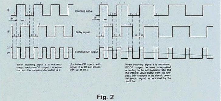
The DGL detector incorporates 19 serially connected high-speed C-MOS ICs, as shown in Fig. 1. The phase angle is delayed by 114° to minimize distortion and to obtain the best signal-to-noise ratio. The delay signal that results and the input signal are applied to an exclusive OR circuit.
The gate circuit is then closed (with 11, 00) or opened (with 10,

Differential Gain Characteristics of Detector Circuit
(interformed (interformed), according to the electric potential between the two signals. The compression ratio of signals produced by modulation is thus detected digitally (i.e., logical multiplication is performed), and sound signals are obtained (Fig. 2). Because the linear range of the delay circuit is extremely wide (±5MHz) and the circuit requires no adjustment, stable and high-grade linear differential gain characteristics can be obtained. Should the radio interference be strong, the NARROW IF filter can be selected by switching operation on the front panel, thus allowing reception with emphasis on the selectivity.
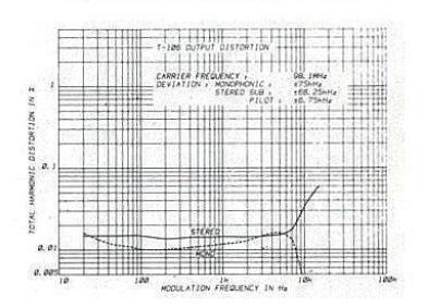
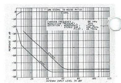
The FM stereo demodulator, which integrates the newest technology available, realizes near-perfect performance characteristics, shown here in actual measurements.
Stereo separation : 68dB (1kHz) Total harmonic distortion : 0.004% (1kHz MONO) Signal-to-noise (S/N) ratio : 97dB Subcarrier product ratio : 82dB reception is unclear because of a weak input signal. (20)
When reception is unclear because of a weak input signal, (20dBf or less), the monophonic mode is automatically selected to clear it up.
ts superb design employs both the section and the Synchronous

The audio circuit in the following stage is made of specially selected components and has been designed with sound quality foremost in mind.
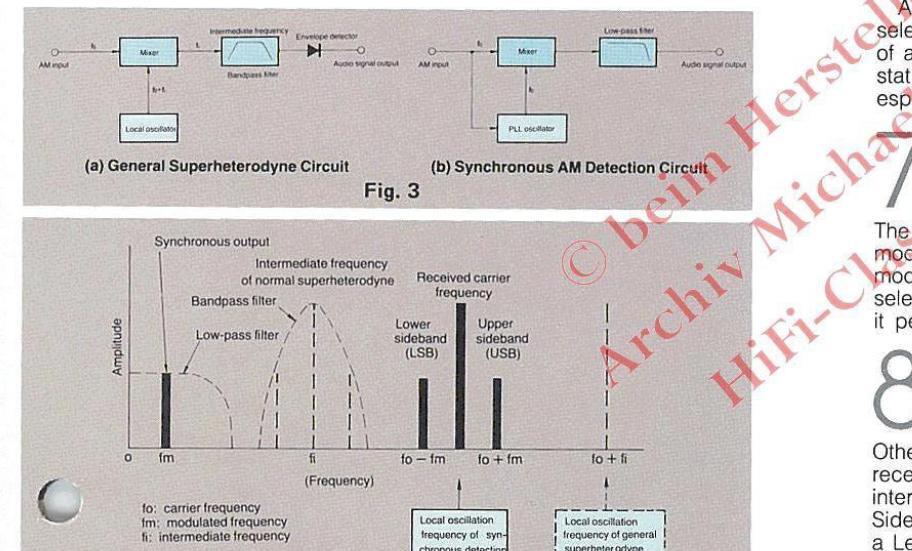
Undesired Desired Station Undesired Station Usb USB: Upper sideband Usb USB: Lower sideband To tune in The USB side To tune in To tune in The USB side Fig. 5 Principle of Synchronous Detector AM Tuner Avoiding Interference by SIDEBAND SELECTOR Switch CThe carrier of an AM radio wave has two sidebands produced by modulation on both sides.)
Fig. 4 Principle of Synchro
AM SYNCHRONOUS DETECTOR COMPLETELY REJECTS INTERFERENCE AND ACHIEVES LOW DISTORTION
As a consequence of stress on the importance of AM reception, the T-106 uses a synchronous detector with superior capabilities in eliminating interference. This is in addition to a standard wideband superheterodyne circuit, and a 9kHz filter eliminates beats from adjacent stations.
Accuphase [-]
Logic Control Circuit Equipped with AM/FM Synthesizer, Function Memory, Pulse Tuning
Synthesizer AM-FM Tur
Fig. 3 (a) shows the system diagram of a superheterodyne receiver, which is generally used. Fig. 3 (b) shows the diagram of the synchronous detector, which collectively detects audio signals, as shown in Fig. 4, by inputting to the mixer the local oscillation frequency matched with the input carrier.
Selectivity is determined according to the characteristics of the low-pass filter provided on the audio circuit. The synchronous detector causes minimum distortion and is expected to become a standard component when AM stereo broadcasting gains in popularity.
AM stereo broadcasting gains in popularity. Another outstanding feature of the synchronous detector is that it allows selection of a sideband, shown in Fig. 5, depending on whether the frequency of an undesired station is higher or lower than the frequency of a desired station. Because sky waves are stronger at night, the synchronous detector is especially useful when station interference poses problems.
TWO INDICATION METERS
The 106 has a signal strength meter measuring in dBf and a peak modulation meter that can indicate up to 200% of modulation ratio. The modulation meter also functions as a multipath detection meter, which allows selection of the best antenna direction for minimum distortion. Which function it performs is determined through a pushbutton switch.
OTHER FEATURES
Other available features include a Multiplex Noise Filter to reduce noise when receiving a weak FM stereo station; a Selectivity Switch for use when interference is strong; a Multing Switch to eliminate interstation noise; a Sideband Selector to select the AM sideband when there is interference, and a Level Control to equalize tuner output level with other program sources.

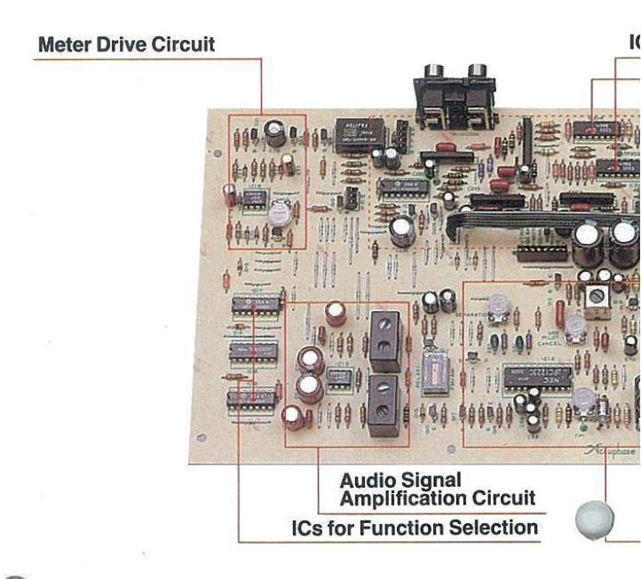
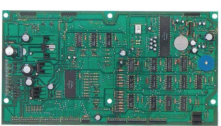
AM/FM Tuner Printed-Circuit Board
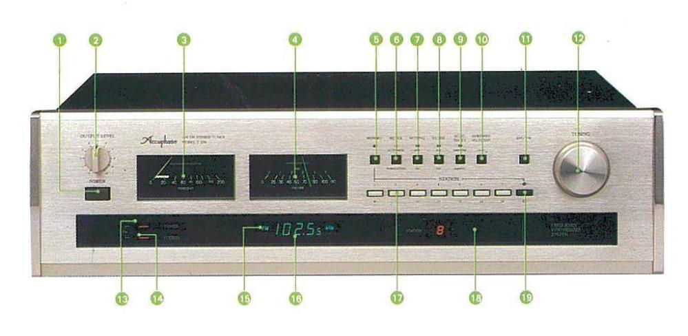
Top View of T-106
- POWER switch
- OUTPUT LEVEL control knob
- Peak indicating type modulation/FM multipath meter
- O Sional strength meter
- MEMORY button
- MODULATION/MULTIPATH selector switch
- MUTING (FM interstation noise silencing) switch
- (3) FM multiplex noise FILTER
- FM SELECTIVITY selector switch
- AM SIDEBAND selector switch
- AM/FM selector switch
- P Optical pulse TUNING knob
- E FM TUNED indicator
- TEREO indicator
- AM/FM indicator
- Tuned frequency indicator
- Memory STATION selector button
- © Station number indicator
- Upper/lower station pushbutton selector
- FM ANTENNA connector
- AM ANTENNA connector
- Loop antenna
- FIXED level output jack
- Power cord
- CONTROLLED level output jack

GUARANTY SPECIFICATIONS
PERFORMANCE GUARANTY: All Accuphase product specifications are guaranteed as stated.
FM MONOPHONIC PERFORMANCE
- FREQUENCY RANGE: 87.5 MHz-108.0 MHz Usable Sensitivity: 11 dBf (IHF)
- Usable Sensitivity: 11 dBf (IHF) 50 dB Quieting Sensitivity: 17 dBf (IHF) VOLTAGE STANDING WAVE RATIO: 1.5 SIGNAL TO NOISE RATIO AT 80 dBf:
- SIGNAL TO NOISE RATIO AT 80 83 dB (A-Weighted) TOTAL HARMONIC DISTORTION
- I UTAL HAHMUNIC DISTORTION: with SELECTIVITY switch set to NORMA 80 dBf input at ±75 kHz deviation 20 Hz 1,000 Hz 10,000 Hz 0.04% 0.04%
- INTERMODULATION DISTORTION: Will not exceed 0.01% (Antenna input 80 dBf, ±75 kHz deviation, 14 kHz and 15 kHz = 1:1)
- FREQUENCY RESPONSE
- SELECTIVITY: (IHF)
-
SELECTIVITY: (IHF) With SELECTIVITY switch set to
- NORMAL NARROW
- NORMA Alternate Channel: 70 dB Adjacent Channel: 8 dB CAPTURE RATIO: 1.5 dE
- CAPTUHE RATIO: 1.5 dB REINTERMODULATION: 80 dB SPURIOUS RESPONSE RATIO: 120 dB IMAGE RESPONSE RATIO: 80 dB IF/2 SPURIOUS RESPONSE RATIO: 100 dB AM SUPPRESSION RATIO:
- 80 dB at 65 dBf input SUBCARRIER PRODUCT RATIO: 70 dB
- SCA REJECTION RATIO: 80 dB
- 1.0 Volt at ±75 kHz deviation
- FM STEREOPHONIC PERFORMANCE
- SENSITIVITY:
- 40 dB Quieting Sensitivity: 29 dBf (IHF) 50 dB Quieting Sensitivity: 37 dBf (IHF) SIGNAL-TO-NOISE RATIO AT 80 dBf:
- 79 dB (A-Weighted) TOTAL HARMONIC DISTORTION: With SELECTIVITY switch set to ive dBf input at ±75 kHz deviation NORMAL 80 1,000 Hz 0.04%
- 0.08% 0.04% 0.04% 0.08% INTERMODULATION DISTORTION:
- Will not exceed 0.03% (Antenna input 80 dB ±75 kHz deviation, 9 kHz and 10 kHz = 1.1) FREQUENCY RESPONSE:
- 10 Hz to 16 000Hz STEREO SEPARATION: 10 000 Hz
- 1,000 Hz
- 100 Hz 1,000 Hz 10,000 Hz 50dB 50 dB 45 dB STEREO AND MUTING THRESHOLD: 20 dBI
AM PERFORMANCE
-
FREQUENCY RANGE:
- 522 kHz—1,611 kHz 520 kHz—1,710 kHz for North America and
- USABLE SENSITIVITY:
- USABLE SENSITIVITY: 20 µV/m at 20 dB S/N IMAGE REJECTION RATIO: 50 dB TOTAL HARMONIC DISTORTION:
- Will not exceed 0.3% (Antenna input 1 mV/m,
- SIGNAL TO NOISE BATIO 50 dB (Antenna input 1 mV/m, 30% mod., 1
- OUTPUT: 0.3 Volt (30% mod.)
GENERAL
- ANTENNA INPUT:
-
-
AM: Loop Antenna TUNING SYSTEM
- requency Synthesized Tuning
- System Preset Tuning at random memory for AM and FM: 14 stations
- Manual-Pulse controlled Tuning System
- FM DETECTOR: DGL Detector (Differential Gain Linear Detector) AM DETECTOR: Synchronous Detector OUTPUT IMPEDANCE:
-
AM: Loop Antenna TUNING SYSTEM
Audio output FIXED: 200 ohms Audio output CONTROLLED: 1.25 kohms max
|
CARRIER FREQUENCY ;
MODULATION FREQUENCY ; DEVIATION ; MONOPHONIC ; STERED SUR ; FILOT |
,
, ,, ,, ,, ,, |
98. 1MHz
1AHz 258Hz 268. 256Hz 268. 256Hz |
|||
|---|---|---|---|---|---|
| X | |||||
|
10 |
- Aller | ||||
| 1 | × | X | |||

- METER: MULTIPATH/MODULATION and SIGNAL STRENGTH meters STRENGTH meters SEMICONDUCTOR COMPLEMENT
- Tr's, 6 FETs, 50 ICs, 63 Di's, 10 LEDs, and 2 opto-interrupters
- Compatible 100/117V and 220/240V 50/60 Hz
-
operation Consumption: 23 Watts DIMENSIONS: 445 mm (17-1/2 in) width, 128 mm (5-1/16 in) max. height, 370 mm (14-9/16 in) depth WEIGHT:
- 9 kg (19.8 lb) net, 13 kg (28.6 lb) in shipping


 Loading...