

Page 1
● AC voltage stabilizer based on waveform shaping technology ● Supplies up
to 510 VA of extremely clean energy ● Low-distortion reference waveform
generator ● Highly effective waveform compensation ● Outstanding current
capability ● Superb interference rejection ● Built-in meter for monitoring five
vital parameters: output power, input/output voltage, input/output distortion
● Elaborate protection features ● Large “Super Ring” toroidal transformer
The photograph shows the 230 V version.
Page 2
Tap into a totally clean source of AC energy for up to 510 VA – Revolutionary
waveform shaping technology enables highly precise compensation,
creating a pure energy source of 230 V AC (or 120 V AC) ±2% with max.
0.22% THD. Connect audio or video equipment for a drastic improvement
in sound and picture quality. Monitor output power (VA), input/output
voltage (V), and input/output distortion (%) on the built-in meter.
The Clean Power Supply components from
Accuphase are revolutionary products that
remove noise and impurities from the AC power
line and improve signal quality by continually
monitoring and shaping the power supply
waveform. They have been widely acclaimed
for drastically improving the sound and picture
quality of audio and video equipment. The
PS-510 is an upgraded version that
incorporates latest MCS+ circuit topology in the
waveform compensation amplifier section. The
reference signal generator features further
improved accuracy to assure the lowest possible
distortion in the output waveform.
The PS-510 uses waveform shaping technology
to turn the power from a regular AC outlet into
a highly pure sine waveform for use as a stable
and uncontaminated energy source of A/V
components. To achieve this, the PS-510 takes
the power source waveform and compares it to
a highly accurate and stable reference
waveform. Based on this comparison, it then
adds or subtracts exactly the required amount
of correction. The compensation required by
this innovative technique typically is only a
fraction of overall power. The PS-510 therefore
operates with high efficiency and produces little
heat, allowing it to be designed as a fairly
compact and lightweight unit. Since all circuitry
is analog and there are no oscillators or
switches, the PS-510 itself does not act as a
source of spurious high-frequency noise.
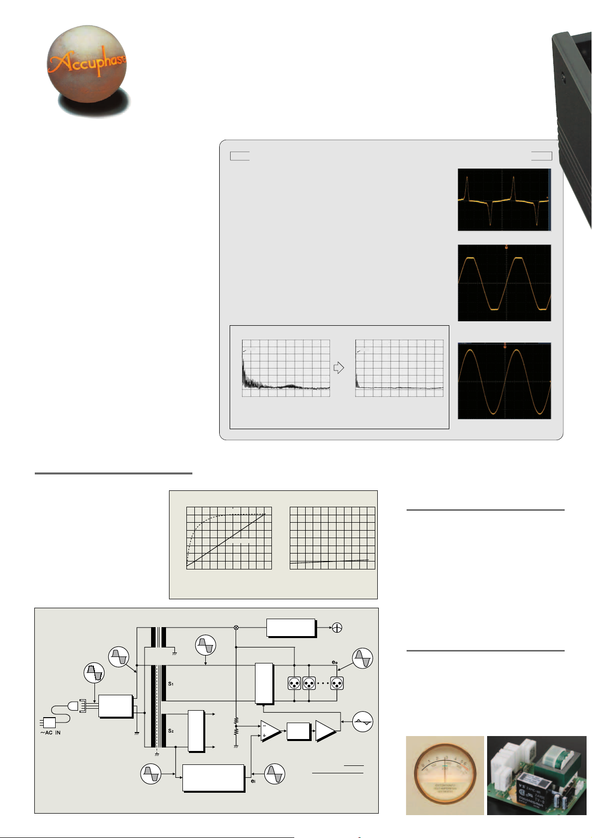
Power Supply Waveform and Clean PS-510 Output Waveform
Almost all electrical devices used in a household convert the AC supplied
by the outlet into a DC current for powering internal circuits. This task is
performed by a rectifier. As shown in photograph a, the rectifier load
current has a pulse waveform with a large current flowing momentarily in
the vicinity of the voltage peak.
This causes a voltage drop, resulting in clipping of the voltage waveform,
as shown in photograph b. A clipped waveform with a high amount of
distortion contains many unwanted frequency components, or harmonics,
as shown below. When entering the audio circuitry of an amplifier through
the power supply, such harmonic components can interfere with the audio
signal and cause intermodulation distortion which has a highly detrimental
effect on sound quality.
When passing through the PS-510, the deformed waveform is restored to
its original sine wave pattern (see frequency spectrum in the graph below).
The result is a clean sine waveform as shown in photograph c.
[dB]
0.0
50Hz
-25.0
-50.0
-75.0
-100.0
0 10k 20k
Frequency spectrum of power line (photo b)
Frequency spectrum of power line
[dB]
0.0
50Hz
-25.0
-50.0
-75.0
-100.0
0 10k 20k
Frequency spectrum of PS-510 output
(photo c )
Photo a Current waveform of rectified load
Photo b Voltage waveform of AC line
[Hz][Hz]
Photo c PS-510 output waveform
(distortion approx. 3%)
(distortion approx. 0.2%)
AC Voltage Stabilizer Based on Waveform Shaping
Technology
The PS-510 accepts AC power on the input side,
processes it using internal control circuitry,
and supplies it as clean AC power on the
output side. Most of the AC energy from the
input is carried over to the output. The loss
introduced by the PS-510 is very small,
since it consists only of the power required
for waveform compensation.
As shown in Figure 1, the signal from the
secondary winding S
1 of the transformer
ciency
Effi-
Input
power
[%]
[VA]
80
800
60
600
40
400
20
200
reaches the adding/subtracting circuit and
appears at the output as output voltage
0). The S2 signal from the transformer goes
(e
to the reference waveform generating circuit
Line filter
where it becomes a high-precision sine waveform (e
synchronized to the input frequency of 50/60 Hz.
This reference sine wave (e
i) is then used as refer-
ence signal to be compared to the output voltage.
THD
Load: purely resistive Load: purely resistive
Efficiency
Input/output power
0 100 200 300 400 500
Output power/input power (efficiency)
characteristics
Output power [VA]
[%]
0.8
0.6
0.4
0.2
0
100 200 300 400 500
Output power/THD characteristics
Fig. 2 PS-510 Load Characteristics
Meter selector
buttons
Rectifier
Reference signal
generator
Alarm indication
circuit
Adding/sub-
tracting circuit
Wavefo rm
comparator
Error
detector
Waveform compensation
amplifier using "MCS+"
and "Current feedback"
circuitry
Meter
Output power [VA]
AC
OUTPUTS
i)
The differential component is extracted and used by
the adding/subtracting circuit to provide exactly the
required amount of compensation for turning the output into a high-precision sine waveform.
Highly Effective Interference Rejection
The input side of the PS-510 is equipped with a line
filter for removing any high-frequency noise
components present in the power line, such as
generated by digital equipment. The primary and
secondary windings of the power transformer are
kept totally separate, and the fully shielded design
shuts out any externally induced noise. Since the
amplifier uses the feedback principle, output
impedance is extremely low. This prevents any
possibility of mutual interference between components
connected to the outputs of the PS-510.
Built-in Meter Allows Monitoring of 5 Parameters:
Output Power, Input/Output Voltage, Input/Output
Distortion
The meter of the PS-510 lets the user see at a
glance how much power (VA) the connected equipment
is consuming at any given time. This is especially
helpful for components such as integrated amplifiers
or power amplifiers whose power consumption differs
considerably depending on the volume setting and
actual music signal. When the maximum rated output
power of 510 VA is exceeded, the meter illumination
flashes as a warning indication.
Fig. 1 Operation Block Diagram of PS-510
Meter of 230 V AC version
Assembly with input voltage/
distortion monitoring circuitry
Page 3

The photograph shows
the 230 V version.
The power amplifier which performs waveform compensation uses the current feedback principle
for excellent high-frequency phase characteristics and operation stability. This is combined with
the MCS+ circuit renowned for superior performance and sound quality. The output stage uses
10 transistors rated for a maximum current of 15 amperes. These devices are connected in a
parallel complementary push-pull arrangement which boasts a rated output current of
2.2 A (4.2 A) and an instantaneous peak current (inrush current) rating of 30 A (60 A). This
demonstrates the excellent current capability of the PS-510.
Note: The explanation is for the 230 V AC version of the PS-510. Figures in brackets refer to the 120 V AC version.
Compensation Amplifier Based on High-Precision Reference Signal Creates Pure 230 V (or 120 V) AC Source
■■
■ Low-Distortion Reference Signal Generator
Excellent Current Capability
■■
The waveform of the signal detected at the S2 winding of the power transformer (see
Fig. 1) is used by a highly precise Zener diode circuit to generate a square waveform.
A newly developed 50/60 Hz bandpass filter and band-eliminate filter is then applied
to the waveform. The filter
frequency is switched in sync with
the input frequency, for automatic
50 Hz and 60 Hz support. By routing
the signal through another
bandpass filter, a low-distortion
sine wave (reference signal) is
created that is not dependent on
the input voltage.
Square wave
generator
From
secondary
winding of
power
transformer
[50Hz]
[60Hz]
Reference Signal Generator Block Diagram
■ ■
■ Assembly with reference signal generator and other circuitry
■ ■
Bandpass
filter
Bandpass
filter
Band-
eliminate
filter
Band-
eliminate
filter
Bandpass
filter
Reference
output
waveform
■■
■ Superior Waveform Compensating Power
■■
When the input voltage is 220 V (110 V), the voltage at the secondary side of the transformer will also
be 220 V (110 V). To bring this to 230 V (120 V), 10 volts must be added, as shown in Figure (a).
Conversely, if the input is 240 V (130 V), 10 volts must be subtracted to yield 230 V (120 V), as shown
in Figure (b). (As the figures show, in actual operation, the peak value of 10 V, namely 14.1 V, is added
or subtracted.) The sine wave (e
i) synchronized to the input frequency and the output voltage (e0) are
compared, and for any excessive or missing component, a compensation waveform up to a maximum
of ±10 V (peak value
+170/
325 V
PS-510
230/120 V AC
output waveform
14.1 V
220/110 V
AC input
waveform
0
±14.1 V) is generated
and imposed on the
output voltage. Con-
sequently, for an input
voltage range of 200-
253 V AC (108-132 V
AC) at the rated load
of 510 VA , the output
voltage is kept con-
stant at 230 V ±2%
(120 V ±2 %), with a
maximum distortion
ratio of 0.22%. These
values demonstrate
the outstanding wave-
form compensation
-170/
325 V
Compensation
waveform
+14.1 V
0
-14.1 V
(a) If power source voltage is
lower than 230 V (120 V),
addition is performed
Waveform Shaping Principle of PS-510
ability of the PS-510.
+170/
325 V
t
14.1 V
-170/
325 V
+14.1 V
t
-14.1 V
(b) If power source voltage is
▼ Assembly with 10 parallel push-pull
power transistors mounted to two
large heat sinks, waveform
compensation amplifier for
addition/subtraction, etc.
14.1 V
240/130 V
AC input
waveform
PS-510
230/120 V
AC output
waveform
0
14.1 V
Compensation
waveform
0
higher than 230 V (120 V),
subtraction is performed
t
t
Page 4

Multiple Protection Assures Total Operation Safety
If a problem occurs during operation, the circuit breaker immediately shuts off
the power, to protect the unit and any connected components
from possible damage.
a When the combined load of connected
equipment exceeds the maximum rated
output power of 510 VA, the meter illumination flashes as a warning indication.
b When input current overload occurs, the
circuit protector shuts off the power. Reduce the connected load and turn power
on again.
c In case of momentary power
overload such as caused by
inrush current when a component is switched on or when a
power amplifier reproduces a
peak passage in the music, a
current limiter becomes active
to ensure safe use.
■
Front panel
(The photograph shows the 230 V version.)
Assembly with protection circuitry
★
Circuit protector
Meter of 120 V AC
version
d When DC voltage is detected in the output due to an
operation problem or when the output voltage exceeds
the maximum rating, the output is switched off to protect
connected components.
e When the temperature of the internal heat sink or power
transformer is very high for an extended period, the circuitry is automatically shut down.
Strong Power Supply With Large “Super Ring” Toroidal
Transformer and Two High-Quality 22,000 µF Filtering
Capacitors
The PS-510 uses a large toroidal type power transformer
rated for about 750 VA. The "Super Ring" toroidal power
transformer has large-gauge copper wiring on a donut-shaped
core, resulting in very low impedance and high efficiency.
PS-510 Meter (Power) Indication and Load
The power consumption of electrical equipment, as indicated on the equipment itself and in catalogs and
other documentation according to legal requirements, is usually given in watts (W). This figure represents
the so-called effective power. However, the actual power drawn by the equipment is larger than the
effective power. This is called the apparent power which is calculated by multiplying the applied voltage
(230 V or 120 V) with the actual current. The unit for apparent power is VA (Volt-Ampere).
Since the value shown by the meter of the PS-510 is the apparent power, the reading will be higher than
Option board installation example
the power consumption (W) given in catalogs and specification sheets
● The rated power limit of the PS-510 is 510 VA. When deciding on equipment to be connected, select
components so that the total remains within this limit, and check actual power consumption using the
meter.
● High-output class-A power amplifiers, such as the A-60 or A-50V, which constantly draw a high idling
current when switched on cannot be connected to the PS-510.
● In case of overload, the meter illumination flashes. Reduce the load by reducing the number of
connected components until the illumination stops flashing and stays constantly lit.
● The power consumption of integrated amplifiers and power amplifiers varies considerably depending
on the actual audio output. After connecting such equipment, perform playback and verify that power
consumption does not exceed the maximum rating when peaks in the music are reproduced at high
volume levels.
Gold-plated parts
High-quality, high-reliability circuit components
.
Output connectors of 120 V AC version
■
Rear panel
(The photograph shows the 230 V version.)
A Meter (Output power, input/output voltage, input/
output distortion)
B Power switch/circuit protector
C Meter operation selector buttons
VOLT AMPERE (VA), VOLTAGE INPUT/OUTPUT (V)
DISTORTION INPUT/OUTPUT (%)
Remark
★
The 230 V AC and 120 V AC versions of the PS-510 differ regarding meter voltage indication, AC
output connector shape, supplied power cord, etc. Make sure that you have the correct version.
R
Caution
★
✽
The PS-510 is available in 230 V AC and 120 V AC versions. The actual allowable voltage is indicated next to the AC power connectors on the rear panel. Be sure to check this indication
before using the PS-510.
✽
This product can be used only on a regular household AC circuit rated for 230 V or 120 V AC, 50/60 Hz. Using the product with portable AC generators, airplane or marine power generators
or other types of power sources is not possible.
✽
This product is designed to improve the quality of AC power supplied to audio or video components. Do not use it to power industrial type equipment or common household electrical appliances.
✽
Do not use this unit for powering equipment where failure incurs a risk of injury or fatal accidents (medical equipment, aviation equipment, traffic control equipment, furnace and heating control
equipment, safety devices, etc.). Accuphase will not be liable for any problem occurring due to use of the PS-510 with the above type of equipment.
★
The usable power supply
voltage is indicated here.
D Output connectors (AC outlets)
E AC power connector
21
21
★
GUARANTEED SPECIFICATIONS
120 V version 230 V version
Rated output capacity 510 VA (continuous)
Rated output voltage 120 V AC ±2.4 V 230 V AC ±4.6 V
Rated output current 4.2 A 2.2 A
Instantaneous peak current capacity
Output frequency 50 Hz or 60 Hz (identical to input frequency)
Output waveform THD 0.22% or less
Rated input voltage 120 V AC 230 V AC
Input frequency 50 Hz or 60 Hz
No-load power consumption 55 W
Cooling principle Natural air cooling
Meter
★
VOLT-AMPERE
VOLTAGE INPUT/OUTPUT
★
(green zone of scale)
DISTORTION INPUT/OUTPUT 0-6%
Maximum Dimensions
Mass
60 A 30 A
✽
The meter illumination flashes when an overload occurs.
120 V AC ±5% 230 V AC ±5%
Width 465 mm (18-5/16")
Height 181 mm (7-1/8")
Depth 386 mm (15-3/16")
23 kg (50.7 lbs.) net
29 kg (63.9 lbs.) in shipping carton
0-510 VA
■ Supplied accessories: • AC power cord
• Specifications and design subject to change without notice for improvements.
http://www.accuphase.com/
C0505Y PRINTED IN JAPAN 851-0155-00 (AD1)
 Loading...