

Page 1

● AC voltage stabilizer based on waveform shaping technology ● Acts as a
source of extremely clean energy ● Low-distortion reference waveform generator
●
Highly effective waveform compensation ● Outstanding current capability
● Superb interference rejection ● Built-in meter for monitoring vital parameters
including output power, input/output voltage, and input/output distortion●Advanced
protection features ●Large high-efficiency toroidal transformer●Eight AC outlets
The photograph shows the 230 V version.
Page 2

Tap into a totally clean source of AC energy — Revolutionary waveform
shaping technology enables highly precise compensation, creating a pure
energy source of 230 V AC ±3 V (or 120 V AC ±1.5 V) with max. 0.1%
THD. Connect audio or video equipment for a drastic improvement in
sound and picture quality. Monitor output power (VA), input/output
voltage (V), and input/output distortion (%) on the built-in meter.
The Clean Power Supply components from
Accuphase are revolutionary products that
remove noise and impurities from the AC power
line and improve signal quality by continually
monitoring and shaping the power supply
waveform. They have been widely acclaimed for
drastically improving the sound and picture
quality of audio and video equipment. The
PS-1220 is an upgraded version that
incorporates latest MOS-FET push-pull
differential drive topology in the waveform
compensation amplifier section. The reference
signal generator features further improved
accuracy and is linked to the power section by a
balanced connection to assure the lowest
possible distortion in the output waveform.
Furthermore, the matched output impedance
assures optimum reliability. Because the
PS-1220 can deliver as much as 1200 VA (230 V
AC version) or 1000 VA (120 V AC version), it
covers the requirements of almost any
high-quality A/V system currently on the market.
All signal circuits of the PS-1220 are analog,
employing waveform shaping technology to turn
the power from a regular AC outlet into a highly
pure sine waveform for use as a stable and
uncontaminated energy source for A/V
components. To achieve this, the PS-1220 takes
the power source waveform and compares it to a
highly accurate and stable reference waveform.
Based on this comparison, it then adds or
subtracts exactly the required amount of
correction to create a clean output waveform.
The compensation required by this innovative
technique typically is only a fraction of overall
power. The PS-1220 therefore operates with
high efficiency and produces only a low amount
of heat. Since there are no oscillators or switches
in the signal lines, the PS-1220 itself does not
act as a source of spurious high-frequency noise.
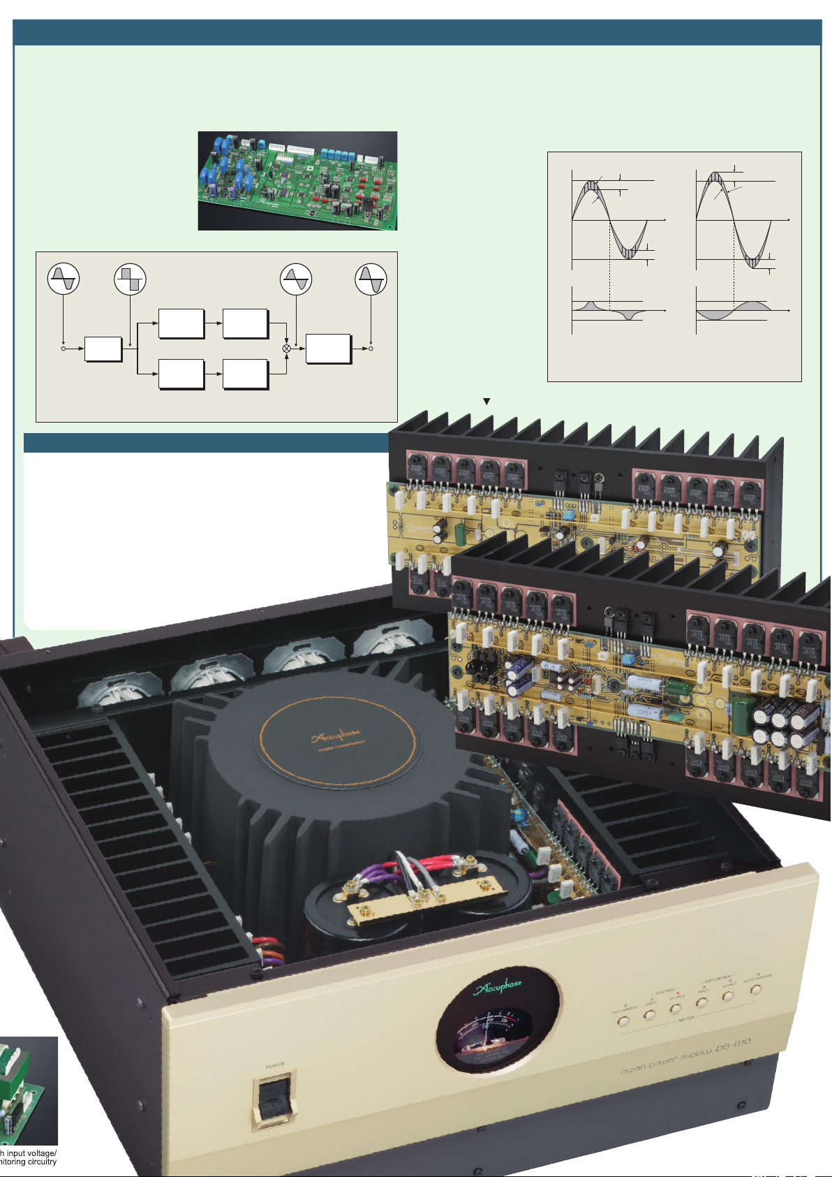
Power Supply Waveform and Clean PS-1220 Output Waveform
Almost all electrical devices used in a household convert the
AC supplied by the outlet into a DC current for powering
internal circuits. This task is performed by a rectifier. As shown
in photograph a, the rectifier load current has a pulse
waveform with a large current flowing momentarily in the vicinity
of the voltage peak. This causes a voltage drop, resulting in
clipping of the voltage waveform, as shown in photograph b. A
clipped waveform with a high amount of distortion contains
many unwanted frequency components, or harmonics, as
shown below. When entering the audio circuitry of an amplifier
through the power supply, such harmonic components can
interfere with the audio signal and cause intermodulation
distortion which has a highly detrimental effect on sound
quality. When passing through the PS-1220, the deformed
waveform is restored to its original sine wave pattern (see
frequency spectrum in the graph below). The result is a clean
sine waveform as shown in photograph c.
PS-1220 OUTPUT POWER SPEC1
〔Hz〕
〔dB〕
0.0
50Hz
−
25.0
−
50.0
−
75.0
−
100.0
0 10k 20k
FrequencyspectrumofPS-1220output(photoc)
Meter selector/
meter control switch
S1
S2
Rectifier
Reference
signal generator
〔dB〕
AC LINE POWER SPEC1
0.0
50Hz
−
25.0
−
50.0
−
75.0
−
100.0
0 10k 20k
Frequencyspectrumofpowerline(photob)
〜AC IN
Frequencyspectrumofpowerline
Line
filter
Photo a Curre nt wav eform of rec tified load
PhotobVoltagewaveformofACline
(distortionapprox.3%)
〔Hz〕
PhotocPS-1220outputwaveform
(distortionapprox.0.06%)
Alarm
circuit
indication
circuit
Adding/
subtracting
Error
Waveform
comparator
detector
Voltagecontrolcircuitry
e
i
Meter
Switch position/
overload warning LEDs
e
o
Outputs
Waveform
compensation amplifier
AC Voltage Stabilizer Based on Waveform Shaping Technology
The PS-1220 accepts AC power on the input side,
processes it using internal control circuitry, and supplies it
as clean AC power on the output side. Most of the AC
energy from the input is carried over to the output. The
loss introduced by the PS-1220 is very small, since it
consists only of the power required for waveform
compensation.
As shown in Figure 1, the signal from the secondary winding S1 of the transformer reaches the adding/subtracting
circuit and appears at the output as output
voltage (e0).
The
secondary winding S2 signal
goes to the reference waveform
generating circuit
where it becomes
a high-precision
sine waveform
(ei) synchronized to the in put
frequency of
50/60 Hz. This
reference sine
wave (ei) is then
used as a reference signal to be
compared to the
output voltage.
The differential
component is ex-
Input power
Efficiency
[VA]
[%]
1800
80
1600
1400
60
1200
1000
40
800
600
20
400
200
0
Output power/efficiency (input power) characteristics
THD[%]
0.8
0.6
0.4
0.2
Output power/THD characteristics
Fig. 2 PS-1220 Load Characteristics
400 600200
400 6002000
Load: pure resistance
Efficiency
Input/output power
Load: pure resistance
800 1000 1200
Output power [VA]
800 1000 1200
Output power [VA]
tracted and used by the adding/subtracting circuit to provide exactly the required amount of compensation for turning the output into a high-precision sine waveform.
Highly Effective Interference Rejection
The input side of the PS-1220 is equipped with a
line filter for removing any high-frequency noise
components present in the power line, such as
generated by digital equipment. The primary and
secondary windings of the power transformer are
kept totally separate, and the fully shielded design
shuts out any externally induced noise. Since the
amplifier uses the feedback principle, output
impedance is extremely low. This prevents any
possibility of mutual interference between
components connected to the outputs of the
PS-1220.
Built-in Meter Allows Easy Monitoring of
Output Power (VA), Input/Output Voltage (V),
and Input/Output Distortion (%). Overload
Indicated by Flashing LEDs.
The meter of the PS-1220 lets the user see at a
glance how much power (VA) the connected
equipment is consuming at any given time. This is
especially helpful for components such as power
amplifiers whose power consumption differs
considerably depending on the volume. When the
maximum rated output power (1200 VA for 230 V
AC version or 1000 VA for 120 V AC version) is
exceeded, the meter function selector LEDs flash
as a warning indication.
Fig. 1 Operation Block Diagram of PS-1220
Page 3
Compensation Amplifier Based on High-Precision Reference Signal Creates Pure 230 V (or 120 V) AC Source
■
■Low-Distortion Reference Signal Generator
To generate the sine wave reference signal, the zero-cross point of the signal at
the S2 winding of the power transformer (see Fig. 1) is detected by an OP amp
and used by a high-precision Zener diode to generate a square waveform. A
newly developed 50/60 Hz bandpass filter and band-stop filter are then applied to
the waveform. The filter frequency
is switched in sync with the input
frequency, for automatic 50 Hz
and 60 Hz support. By routing the
signal through another bandpass
filter, a low-distortion sine wave
(reference signal) is created that
is not dependent on the input
voltage.
From
secondary winding
of power transformer
〔50 Hz〕
Bandpass
filter
Square
wave
generator
Bandpass
〔60 Hz〕
filter
Reference Signal Generator Block Diagram
Assembly with reference signal generator and other circuitry
Band-stop
filter
Bandpass
filter
Reference
Band-stop
filter
waveform
output
Superior Waveform Compensating Power
When the input voltage is 220 V (110 V), the voltage at the secondary side of the
transformer will also be 220 V (110 V). To bring this to 230 V (120 V), 10 volts must
be added, as shown in Figure 2 (a). Conversely, if the input is 240 V (130 V), 10 volts
must be subtracted to yield 230 V (120 V), as shown in Figure 2 (b). (In actual operation, the peak value of 10 V, namely 14.1 V is added or subtracted.) The sine wave
(ei) synchronized to the input frequency and the output voltage (eo) are compared,
and for any excessive or
missing component, a
compensation waveform
up to a maximum of ±10 V
(peak value ±14.1 V) is
generated and imposed
on the output voltage.
Consequently, for an
input voltage range of
200-253 V AC (108-132 V
AC) at the rated load of
1000 VA (1200 VA), the
output voltage is kept
constant at 230 V ±3 V
(120 V ±1.5 V), with a
maximum distortion ratio
of 0.1%. These values
demonstrate the outstanding waveform compensation ability of the
PS-1220.
Assembly with output stage using 20-parallel push-pull power MOS-FETs mounted to two large heat
sinks, waveform compensation amplifier for addition/subtraction, etc.
+
−
PS-1220
(230/120 V AC)
output waveform
+
141V
0
−
141V
14.1V
0
14.1V
(a) If power source voltage is
14.1V
220/120 V
AC input
waveform
Compensation
waveform
lower than 230 V (120 V),
addition is performed
Waveform Shaping Principle of PS-1220
14.1V
+
141V
t
−
141V
+
14.1V
t
−
14.1V
14.1V
PS-1220
230/120 V
AC output
waveform
0
Compensation
waveform
0
(b) If power source voltage is higher
than 230 V (120 V), subtraction is
performed
240/130V
ACinputwaveform
14.1V
t
t
Excellent Current Capability
The power amplifier which performs waveform compensation uses the pure
complementary push-pull differential amplification principle for high raw gain,
outstanding accuracy, and excellent operation stability. The final stage employs
power MOS-FETs to reduce the load on the preceding stage and absorb sudden
load fluctuations with ease. The result is constant and stable power, with high
performance and ideal operation characteristics.
The power section is divided into two symmetrical parts with dedicated left and
right heat sinks. Efficient cooling ensures stable operation for extended periods at
high power.
The output stage uses 20 power MOS-FETs rated for a maximum current of 10
amperes. These devices are connected in a parallel complementary push-pull
arrangement which boasts a rated output current of 12 A (8.3 A) and an
instantaneous peak current (inrush current) rating of 60 A
(120 A). This demonstrates the excellent
current capability of the
PS-1220.
The photograph shows the
230 V version.
Page 4

Multiple Protection Assures Total Operation Safety
If a problem should occur during operation, the circuit
breaker immediately shuts off the power to protect the unit
and any connected components from possible damage.
q When the combined load of
connected equipment exceeds
the maximum rated output
power (1200 VA for 230 V AC
version or 1000 VA for 120 V
AC version), the meter function
selector LEDs flash as a
warning indication.
w
When input current overload
Assembly with protection circuitry
occurs, the circuit protector
shuts off the power. Reduce the connected load and turn power
on again.
e In case of momentary power overload such as caused by
inrush current when a component is switched on or when a
power amplifier reproduces a peak passage in the music, a
current limiter becomes active to ensure safe use.
r When DC voltage is detected in the output due to an
operation problem or when the output voltage exceeds the
maximum rating, the output is switched off to protect
connected components.
■Front Panel
(The photograph shows the 230 V version.)
w
■Rear Panel
(The photograph shows the 230 V version.)
Theusable power supply
voltage is indicated here.
qMeter (Output power, input/output voltage, input/output distortion)
wPower switch/circuit protector
eMeter operation selector buttons
VOLT AMPERE (VA) VOLTAGE INPUT/OUTPUT (V)
DISTORTION INPUT/OUTPUT (%) AUTO-MONITOR
Remark
The 230 V AC and 120 V AC versions of the PS-1220 differ regarding meter voltage indication, AC output connector shape, supplied power cord, etc. Make sure that you have the correct
★
*The PS-1220 is available in 230 V AC and 120 V AC versions. The actual allowable voltage is indicated next to the AC power connectors on the rear panel. Be sure to check this
indication before using the PS-1220.
*This product can be used only on a regular household AC circuit rated for 230 V or 120 V AC, 50/60 Hz. Using the product with portable AC generators, airplane or ship power
!
Caution
generators or other types of power sources is not possible.
*This product is designed to improve the quality of AC power supplied to audio or video components. Do not use it to power industrial type equipment or common household electrical
appliances.
*Do not use this unit for powering equipment where failure incurs a risk of injury or fatal accidents (medical equipment, aviation equipment, traffic control equipment, furnace and heating
control equipment, safety devices, etc.). Accuphase will not be liable for any problem occurring due to use of the PS-1220 with the above type of equipment.
r
q
★
e
Output connectors of 120 V AC version
★
★
t
★
rOutput connectors (AC outlets)
tAC power connector
t When the temperature of the internal heat sink or power
transformer becomes too high, the circuitry is automatically
shut down.
Strong Power Supply With High-Efficiency Toroidal
Transformer and Large Filtering Capacitors
(47,000 μF ×2)
The power transformer plays a vital role in any power
supply. The PS-1220 uses a large toroidal type rated for
1500 VA. Toroidal power transformers have large-gauge
copper wiring on a donut-shaped core, resulting in very
low impedance and high efficiency.
Total of Eight AC Outlets
Eight AC outlets on the rear panel of the unit provide
ample capacity to connect for example a CD player,
preamplifier, power amplifier, and other A/V components,
up to the combined maximum rated power consumption
(1200 VA for 230 V AC version or 1000 VA for 120 V AC
version). The low output impedance of each outlet means
that all operate under the same conditions, so there will
be no difference in sound quality, regardless of which
outlet is chosen.
Meter of 120 V
AC version
PS-1220 Meter (Power) Indication and Load
The power consumption of electrical equipment, as indicated on the equipment itself and in
catalogs and other documentation according to legal requirements, is usually given in watts
(W). This figure represents the so-called effective power. However, the actual power drawn by
the equipment is larger than the effective power. This is called the apparent power which is
calculated by multiplying the applied voltage (230 V or 120 V) with the actual current. The unit
for apparent power is VA (Volt-Ampere).
Since the value shown by the meter of the PS-1220 is the apparent power, the reading will be
higher than the power consumption (W) given in catalogs and specification sheets.
●The rated power limit of the PS-1220 is 1200 VA for the 230 V AC version and 1000 VA for
the 120 V AC version. When deciding on equipment to be connected, select components
so that the total remains within these limits, and check actual power consumption using the
meter.
●In case of overload, the meter function selector LEDs flash. Reduce the load by reducing
the number of connected components until the LEDs stop flashing and stay constantly lit.
●The power consumption of integrated amplifiers and power amplifiers varies considerably
depending on the actual audio output. After connecting such equipment, perform playback
and verify that power consumption does not exceed the maximum rating when peaks in the
music are reproduced at high volume levels.
GUARANTEED SPECIFICATIONS
Rated output capacity 1,000 VA (continuous) 1,200 VA (continuous)
Rated output voltage 120 V AC ±1.5 V 230 V AC ±3 V
Rated output current 8.3 A 5.2 A
Output frequency 50 Hz or 60 Hz (identical to input frequency)
Instantaneous peak current capacity
Output waveform THD 0.1% or less
Rated input voltage 120 V AC 230 V AC
Input frequency 50 Hz or 60 Hz
No-load power consumption 60 W
Cooling principle Natural air cooling
Meter
VOLT-AMPERE
VOLTAGE INPUT/OUTPUT
(green zone of scale)
DISTORTION INPUT/OUTPUT 0-6%
AUTO MONITOR
★
★
DISTORTION OUTPUT in 4-second intervals
Width 465 mm (18-5/16")
Maximum Dimensions Height 243.4 mm (9-9/16")
Depth 500.2 mm (19-11/16")
Mass 41.2 kg (90.8 lbs.) net
50.0 kg (110.2 lbs.) in shipping carton
0-1200 VA
Automatically switches meter from VOLT-AMPERE to
120 A 60 A
The meter function selector LEDs flash when an overload occurs.
120 V version 230 V version
120 V AC ±5% 230 V AC ±5%
Toroidal transformer
Filtering capacitors
version.
Supplied accessories: • AC power cord
• Specifications and design subject to change without notice for improvements.
http://www.accuphase.com/
D1105Y PRINTED IN JAPAN 851-0203-00 (B1)
 Loading...