

Page 1
m Powerful 11-parallel push-pull output stage in each channel delivers
linear power into loads as low as one ohm m Input stage with MCS
topology m Current feedback circuit combines excellent sound quality
with total operation stability m Bridged connection mode allows upgrading
to true monophonic amplifier m Massive Super Ring toroidal transformer
rated for 1.5 kVA m Printed circuit boards made from Teflon material
Page 2
A stereo power amplifier with impressive punch: 1,000 watts into 1 ohm
MCS technology in input stage improves S/N ratio, distortion ratings and
other characteristics. 11 pairs of wide-band high-power transistors in parallel
push-pull configuration for each channel. P ower supply with massive 1.5 kVA
toroidal power transformer supports linear power down to impedances as
low as one ohm. Teflon PCBs with low dielectric constant and minimum loss.
The P-7000 continues the distinguished design policy
of the M-8000. It adds MCS technology in the input
stage and many other refinements. Carefully
selected top quality parts are used throughout. The
design aim was to achieve very low output impedance
(Note 1) and constant drive voltage (Note 2). The
end result is a stereo power amplifier that provides
effortless performance and impeccable sound quality .
In the output stage, 11 pairs of high-power
transistors with a rated collector dissipation of 150
watts are arranged in a parallel push-pull
configuration for each channel. The devices are
mounted to large heat sinks on both sides of the
main chassis for efficient dissipation of thermal
energy generated during operation. As a result, the
amplifier is capable of delivering power in a linear
progression towards lower load impedances: 1,000
watts into 1 ohm, 500 watts into 2 ohms, 250 watts
into 4 ohms and 125 watts into 8 ohms. Speakers
with very low impedances as well as speakers whose
impedance fluctuates drastically can also be driven
with ease. By using the P-7000 in bridged mode, it
is possible to create a monophonic amplifier with
even higher power. This performance is sustained
Note 1: Low amplifier output impedance
When forming the load of a power amplifier, a loudspeaker generates
a counterelectromotive force that can flow back into the amplifier
via the NF loop. This phenomenon is influenced by fluctuations in
speaker impedance, and interferes with the drive performance of
the amplifier. The output impedance of a power amplifier should
therefore be made as low as possible by using output devices
with high current capability. This absorbs the counterelectromotive
force generated by the voice coil and prevents the occurrence of
intermodulation distortion.
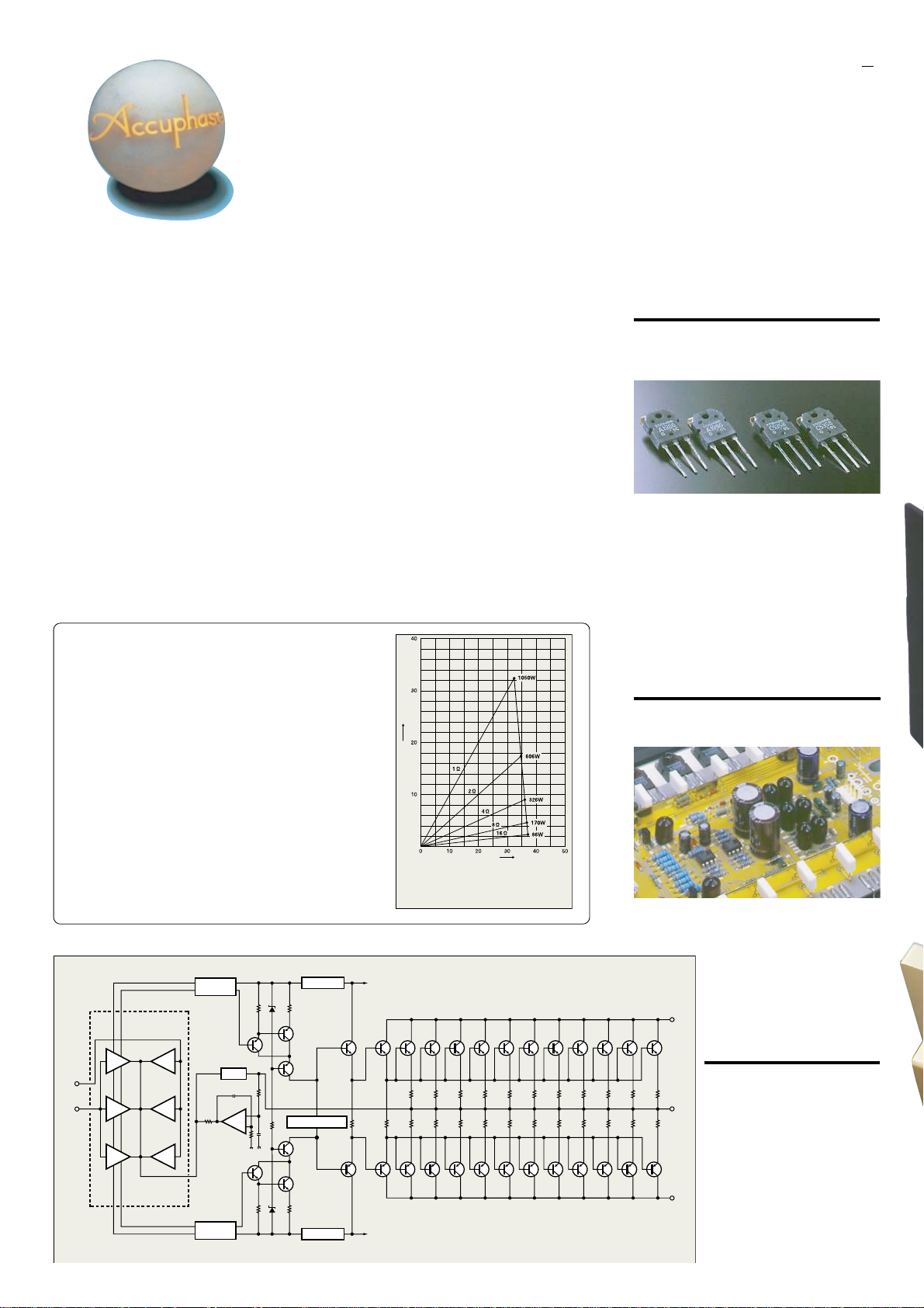
Note 2: Constant drive voltage principle
Even when the impedance of a load fluctuates drastically, the
ideal power amplifier should deliver a constant voltage signal to
the load. Figure 2 is a graph plotting the output voltage versus
current characteristics. Even when the load changes, the output
voltage remains almost constant, showing linear current
progression. Actual measurement of clipping power at the
extremely low load impedance of 1 ohm yields 1,050 watts. At 2
ohms, the figure is 606 watts, at 4 ohms 326 watts, and at 8 ohms
170 watts. This demonstrates the impressive performance reserves
of this amplifier.
REGULATOR
Q
15
Q
17
BIAS STABILIZER CIRCUIT
Q
18
Q
16
REGULATOR
Q
19
Q
–
+
INPUT
INPUT
MCS
(Multiple Circuit Summing-up)
Q
1-4
Q
5-8
Q
9-12
BIAS STABILIZER
CIRCUIT
Q
CIRCUIT
NFB
NETWORK
13
+
–
Q
14
IC
1
IC
2
IC
3
BIAS STABILIZER
by a massive Super Ring toroidal transformer housed
in a diecast enclosure with directly mounted heat
sinks, and by large filtering capacitors. The
transformer is rated for 1.5 kVA, and there are two
capacitors of 56,000 µF each. This assures more
than ample reserves and allows the amplifier to
meet even the most demanding and rapidly
fluctuating power requirements.
The important input stage also has been given due
attention. Another Accuphase innovation called MCS
(Multiple Circuit Summing) helps to minimize noise.
Current feedback topology combines total operation
stability with excellent frequency response, while
requiring only minimum amounts of negative
feedback. The material used for printed circuit boards
has a decisive influence not only on electrical
characteristics but also on the sonic end result.
The P-7000 uses Teflon boards with extremely low
dielectric constant and low loss. The copper foil
side of PCBs and all input and output terminals as
well as all major signal carrying points are gold
plated. Balanced inputs help to shut out external
noise. The overall result of these measures is musical
purity that leaves nothing to be desired.
Output current (A)
Output voltage (V)
* 1-ohm operation possible with
music signals only
Fig. 2 Output power vs. load impedance
(output voltage/output current: actual measurements)
+
B
1
Q21Q23Q25Q27Q29Q31Q33Q35Q37Q39Q41Q
20
–
Q26Q28Q30Q32Q34Q36Q38Q40Q42Q
Q
Q
24
22
B
1
Fig. 1 Circuit diagram of amplifier section (one channel)
11-parallel push-pull power unit delivers guaranteed
linear power output of 1,000 watts into 1 ohm, 500
watts into 2 ohms, 250 watts into 4 ohms and 125
watts into 8 ohms
The output stage uses high-power transistors with a
rated collector dissipation of 150 watts and collector
current of 15 amperes. These devices boast excellent
frequency response, current amplification linearity,
and switching characteristics. The transistors are
arranged in an 11-parallel push-pull configuration
(Figure 1) for ultra-low impedance and mounted on a
massive heat sink made from diecast aluminum. This
assures effective heat dissipation and allows the
amplifier to effortlessly handle very low impedances.
Power linearity is maintained down to loads as low as
1 ohm, which demonstrates the impressive
capabilities of this amplifier.
MCS topology in input stage drastically improves
S/N ratio, distortion, and other characteristics
The input stage features Accuphase's original MCS
(Multiple Circuit Summing-up) design. Three separate
unit amplifiers for the input signal are connected in
parallel, which minimizes noise and
distortion and greatly improves other
performance parameters as well. This
manifests itself in further improved
sound quality.
+
B
2
Current feedback circuit topology
43
prevents phase shifts in high
frequency range
The P-7000 employs the original
Accuphase current feedback principle.
At the sensing point of the feedback
OUTPUT
loop, the impedance is kept low and
current detection is performed. An
impedance-converting amplifier then
turns the current into a voltage to be
44
used as the feedback signal. Since
the impedance at the current
–
B
2
feedback point (current adder in
Figure 3) is very low, there is almost
no phase shift. Phase compensation
can be kept to a minimum, resulting
in excellent transient response and
Page 3

Current
– Input
+ Input
Buffer
Fig. 3 Principle of current feedback amplifier
adder
I-V
converter
Trans-impedance
amplifier
Current NFB
network
Amplifier
Output
superb sonic transparency . Minimal amounts of NFB
are used for maximum effect, providing natural energy
response.
Figure 4 shows
frequency
response for
different gain
settings of the
current
feedback
amplifier. The
graphs
Fig. 4 Frequency response with current feedback
(Response remains uniform even when gain changes)
demonstrate
that response remains
uniform over a wide
range.
Printed circuit boards made from Teflon with low
dielectric constant and low loss
The printed circuit boards for the signal-carrying
circuits are made of Teflon, a glass fluorocarbon
resin material. Teflon has extremely low specific
inductive capacity which is desirable for fast signal
transmission. The low dielectric dissipation factor
results in minimal transmission losses. High-frequency
characteristics and heat resistance are also excellent.
For further improved sound quality, the copper foil
side is gold plated.
* T eflon is a registered trademark of DuP ont USA.
n Power amplifier assembly with 11 parallel
push-pull transistor pairs per channel
mounted directly to large aluminum diecast
heat sinks, MCS circuitry, and current
feedback amplifier
Robust power supply with “Super Ring” toroidal
transformer and high filtering capacity
The P-7000 features a massive toroidal power transformer with a maximum rating of 1.5 kVA. The transformer is housed
in a non-resonant
aluminum case
filled with a material that transmits
heat and absorbs
vibrations. This
completely prevents any adverse influences
on other circuit
parts. A toroidal
transformer uses
heavy-gauge copper wiring on a
doughnut-shaped
core. This results
in low impedance
and high efficiency, while allowing compact
dimensions.
T wo ultra-large aluminum electrolytic capacitors rated
for 56,000 µF each serve to smooth out the pulsating
direct current from the rectifier, providing more than
ample filtering capacity.
Page 4

Bridged connection allows upgrading to a true
monophonic amplifier with 2,000 watts into 2
ohms, 1,000 watts into 4 ohms, and 500 watts
into 8 ohms.
Bridged connection results in a monophonic
amplifier with four times the power output
compared to stereo operation. Dynamic power
with an almost unlimited feel is the result.
Easy switching between dual mono operation
and bridged connection
A mode selector on the
rear panel makes it
simple to switch
between dual mono,
stereo, or bridged
operation.
n Balanced connection prevents induced noise
n PCB copper foil and all major signal path
components are gold-plated
n Large direct-reading analog
power meters
n Oversize speaker terminals
accept also very heavy-gauge
speaker cable
Assembly with meter and protection circuitry
Unbalanced and balanced input
connectors
High-quality, high-reliability partsLarge size speaker terminals Gold-plated parts
n Front panel
n Rear panel
00
A Power meters
(Output indication in dB and %)
B Meter operation/illumination switch
ON OFF
C Power switch
D Speaker output terminals
E Mode selector
DUAL MONO NORMAL BRIDGE
F Unbalanced inputs
Remarks
0
This product is available in versions f or 120/230 V AC . Make sure that the voltage shown on
the rear panel matches the AC line voltage in your area.
0
The shape of the AC inlet and plug of the supplied power cord, and the circuit breaker
current rating depend on the voltage rating and destination country.
G Balanced inputs
a Ground
b Inverted (–)
c Non-inverted (+)
H Input selector
BALANCE UNBALANCE
I AC circuit breaker
J AC input connector
(for supplied power cord)
0
0
Parallel drive of output devices
Semiconductor devices for high frequency applications usually employ a multi-chip design
where a number of small transistors or FETs are connected in parallel. This approach allows
reducing inherent impedance and residual noise as compared to single device operation. In
other words, linearity is improved. In physical terms, increasing the surface area of the chip
prevents spot overheating by providing better heat dissipation, resulting in more stable operation.
Parallel connection in the output stage of the P-7000 uses a similar principle for distributing
the current, which lets the amplifier easily deal with sudden demands for high current, such
as caused by pulsive source signals. However, a parallel circuit as implemented by Accuphase
is much more than a simple physical connection. Accuphase's extensive know-how gained
through many years of intensive research and experimentation is in evidence here. Careful
control of temperature characteristics, current matching of individual devices, and many other
advanced measures are implemented. The overall result is minimized distortion at low currents
and improved S/N ratio, which manifests itself as dramatically improved clarity and transparency
at low listening levels. Ample current reserves make it possible to drive even extremely low
loads with effortless authority. No-holds-barred performance and superb sound are the hallmarks
of Accuphase amplifiers.
GUARANTEED SPECIFICATIONS
[Guaranteed specifications are measured according to EIA standard RS-490.]
m Continuous Average Output Power (20 - 20,000 Hz)
Stereo operation 1,000 watts per channel into 1 ohm (✽)
(both channels driven) 0 500 watts per channel into 2 ohms
Monophonic operation 2,000 watts into 2 ohms (✽)
(bridged connection) 1,000 watts into 4 ohms
m Total Harmonic Distortion Stereo operation (both channels driven)
m Intermodulation Distortion 0.003%
m Frequency Response At rated output: 2 0 - 020,000 Hz +0, –0.2 dB
m Gain 28.0 dB (in stereo and monophonic operation)
m Output Load Impedance Stereo operation: 2 to16 ohms
m Damping Factor 300 (stereo/monophonic operation)
m Input Sensitivity (with 8 ohm load) Stereo operation 1.26 V for rated output
m Input Impedance Balanced: 40 kilohms Unbalanced: 20 kilohms
m Signal-to-Noise Ratio 122 dB at rated output (A-weighted, input shorted)
m Output Level Meters Logarithmic scale, dB/% indication
m Power Requirements AC 120V / 230V , 50/60 Hz
m Power Consumption 125 watts idle
m Maximum dimensions Width 465 mm (18-5/16”)
m Weight 49.5 kg (109.1 lbs.) net
0 250 watts per channel into 4 ohms
0 125 watts per channel into 8 ohms
0 500 watts into 8 ohms
Note: The rating marked (✽) is f or music signals only .
0.05%, with 2 ohm load
0.03%, with 4 to 16 ohm load
Monophonic operation (bridged connection)
0.03%, with 4 to 16 ohm load
At 1 watt output: 0.5- 160,000 Hz +0, –3.0 dB
0 Driving 1Ω loads in stereo operation
Monophonic operation: 4 to16 ohms
Monophonic operation 2.52 V for rated output
(Voltage as indicated on rear panel)
930 watts in accordance with IEC-65
Height 258 mm (10-3/16”)
Depth 545 mm (21-7/16”)
59.0 kg (130.1 lbs.) in shipping carton
0.11 V for 1 watt output
0.11 V for 1 watt output
and 2Ω loads in monophonic operation
is possible with music signals only.
n Supplied accessories: • AC power cord
• Specifications and design subject to change without notice for improvements.
F0310Y PRINTED IN JAP AN 850-0123-00 (AD1)http://www.accuphase.com/
 Loading...