

Page 1
m Powerful 6-parallel push-pull output stage deliv ers linear
power into ultra-low impedance loads m Current feedback
guarantees great sound and stable operation m Bridged
connection mode allows upgrading to true monophonic
amplifier m Printed circuit boards made from T eflon material
m Massive Super Ring toroidal transformer rated for 1 kV A
Page 2
Astounding energy emerging from perfect poise – witness a stereo po wer
amplifier capable of delivering 720 watts (actual measurement) into 1ohm loads. Massive power supply with 1000 VA toroidal transformer
and wide-band high-power transistors in 6-parallel push-pull
configuration ensure constant-voltage drive. Teflon printed circuit
boards feature low dielectric constant and low loss. Current feedback
topology guarantees stable operation up to ultra high frequencies.
Accuphase power amplifiers are designed to
realize two major goals: very low output
impedance (Note 1), and constant drive voltage
(Note 2). As a result, Accuphase amplifiers are
capable of driving any kind of speaker load with
optimum results, which is one of the reasons
behind the high praise that these products
invariably receive. The low impedance not only
ensures accurate speaker driv e b ut also absorbs
the counterelectromotive force generated by the
voice coil, thereby eliminating a major source of
intermodulation distortion. The ove rall result is a
significant improvement in sound quality.
The P-650 is a stereo power amplifier which fully
implements these advanced circuit design
principles. Using only strictly selected high-quality
parts, this product was designed with a full
mastery of all aspects of amplifier performance.
The output uses six pairs of high-power transistors
in each channel, arranged in a parallel push-pull
configuration. These devices are mounted to
massive heat sinks located on both sides of the
unit, for efficient dissipation of thermal energy.
Power linearity is maintained down to extremely
low load impedances. This allows the amplifier to
easily drive even speakers with very low
impedance or uneven impedance curves . By using
the P-650 in bridged mode, you can create a mono
amplifier with even more impressive power
reserves.
Current feedback topology combines total
operation stability with excellent frequency
response, while requiring only minimal amounts
of negative feedback. The printed circuit boards
of the P-650 are made of a Teflon material with
extremely low dielectric constant and low loss,
resulting in more transparent sound. The front
panel in traditional champagne gold features two
large analog power meters. The elegant and
sophisticated appearance of the amplifier will
enhance every listening room.
BIAS STABILIZER
CIRCUIT
Q
–
+
INPUT
INPUT
Q
Q
1
2
BIAS STABILIZER
CIRCUIT
3
Q
4
–
Q
+
+
–
5
Q
6
Figure 1 Circuit diagram of amplifier section (one channel)
Note 1: Low amplifier output impedance
The load of a power amplifier, namely the loudspeaker generates a
counterelectromotive force that can flow back into the amplifier via the NF
loop. This phenomenon is influenced by fluctuations in speaker impedance,
and interferes with the drive perfo rmance of the amplifier. The output impedance
of a power amplifier should therefore be made as low as possible by using
output devices with high current capability.
Note 2: Constant drive voltage principle
Even in the presence of a load with wildly fluctuating impedance, the ideal
power amplifier should deliver a constant voltage signal to the load. When the
supplied voltage remains constant for any impedance, output power will be
inversely proportional to the impedance of the load. A conventional amplifier
can be easily made to operate in this way down to a load impedance of about
4 ohms. Howe ver , at 2 ohms and below , much more substantial output reserves
are needed, which can only be sustained by an extremely well designed and
capable output stage and a highly robust and powerful power supply section.
To build such an amplifier is a task that requires not only considerable
experience and resources but also a thorough reappraisal of basic tenets.
Power units with 6-parallel push-pull
configuration deliver ample linear power: 400
watts into 2 ohms, 200 watts into 4 ohms, or
100 watts into 8 ohms
The output stage uses high power transistors with
excellent linearity and switching characteristics,
rated for a collector dissipation of 130 watts and
collector current of 15 amperes. These transistors
are arranged in a 6-parallel push-pull configuration
(Figure 1) and mounted on massive heat sinks
made from diecast aluminum, for efficient heat
dissipation. This enables the P-650 to eff ortlessly
drive even speakers with e xtremely low impedance
or with reactive loads.
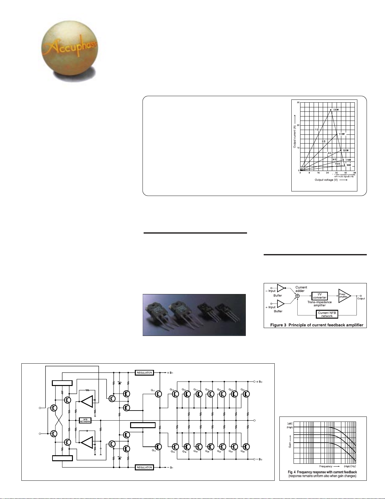
Figure 2 shows the output/voltage characteristics
at various load impedances. It can be seen that
output voltage remains nearly constant regardless
Q
7
Q
9
BIAS STABILIZER CIRCUIT
Q
10
Q
8
REGULATOR
–
B
1
Figure 2 Load impedance vs. output power
(output voltage/output current) of P-650
of load, which means that output current increases
linearly. The actually measured clipping power is
an impressive 720 watts into 1 ohm, 518 watts
into 2 ohms, 320 watts into 4 ohms, or 178 watts
into 8 ohms.
Current feedback circuit topology prevents
phase shifts
The P-650 employs the so-called current feedbac k
principle. Figure 3 shows the operating principle
of this circuit. At the sensing point of the f eedback
loop, the impedance is kept low and current
detection is performed. An impedance-conv erting
amplifier then converts the current into a voltage
to be used as the feedback signal. Since the
impedance at the current feedback point (current
adder in Figure 3) is very low, there is
almost no phase shift. Phase
compensation can be kept to a minimum,
resulting in excellent transient response
and superb sonic transparency.
Figure 4 shows frequency response for
different gain settings of the current
feedback amplifier. The graphs
demonstrate that response remains
uniform over a wide range.
OUTPUT
Page 3
Bridged mode creates a true monophonic
amplifier with 800 watts into 4 ohms or 400
watts into 8 ohms
Bridged operation means that two amplifiers are
driven by the same signal voltage but with opposite
phase. The P-650 pro vides a switch arrangement
for bridged operation of its two channels, which
turns the unit into a high-grade monaural amplifier
with even higher output capability.
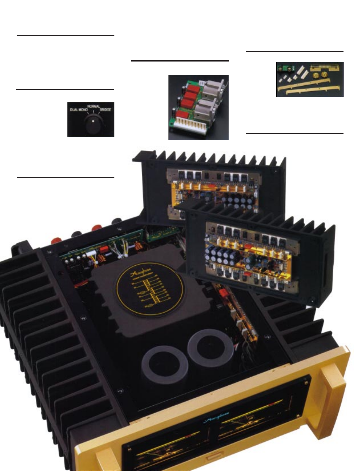
Easy switching between dual mono operation
and bridged connection
A mode selector on the rear panel makes it simple
to switch between dual
mono, stereo, or
bridged operation. The
dual mono position is
useful for example to
drive a center woofer in
mono, or to obtain the
same signal from both
speaker outputs for driving a bi-amped speaker
setup.
minimizes leak currents between patterns and
results in more speedy signal propagation. Low
losses mean further enhanced signal purity. S/N
ratio also is excellent.
* Teflon is a registered trademark of DuPont USA.
Balanced connection reliably blocks induced
noise
Balanced signal transmission means that two
signal lines are
used which carry
the same signal
with opposite
phase. On the
receiving side,
the signals are
mixed. Since any
noise interference that has
arisen during
transmission will
be present in
both lines with identical phase, such noise is
canceled out, leaving only the pure original signal.
Balanced connection therefore keeps the signal
transfer free from an y kind of interference.
All major signal paths gold-plated
The P-650 uses gold-plating for the copper traces
on printed
circuit boards
as well as for
ground bars
carrying large
ripple currents, bus
bars providing current to the power transistors,
input jacks, and speaker terminals. This thorough
approach results in a distinct sonic improvement.
Robust power supply with "Super Ring"
toroidal transformer and high filtering capacity
The P-650 features a large toroidal power
transformer with a rating of about 1 kVA. Toroidal
Printed circuit boards made from Teflon
material (glass cloth fluorocarbon resin) with
low dielectric constant and low loss
The power amplification circuit boards are made
of a glass cloth fluorocarbon resin material which
has a stable, low dielectric constant as well as
superior heat resistance and high-frequency
characteristics. The low dielectr ic constant
n 6-parallel push-pull output stage
with transistors mounted directly
to large aluminum diecast heat
sinks. Power amplifier assembly
with Teflon PCBs and current
feedback amplifier circuitry.
Page 4
power transf ormers
use heavy-gauge
copper wiring on a
doughnut-shaped
core. This results in
circular coil windings with high packing density.
Two ultra-large aluminum electrolytic capacitors
rated for 47,000 µF each serve to smooth the
pulsating direct current from the rectifier, providing
more than ample filtering capacity.
low impedance and
high efficiency,
Extra large speaker terminals
while allowing
compact
dimensions. In
particular, the
"Super Ring"
transformer used in
the P-650 has
various
advantages, such
as the near-circular
core caliber,
allowing near-
nn
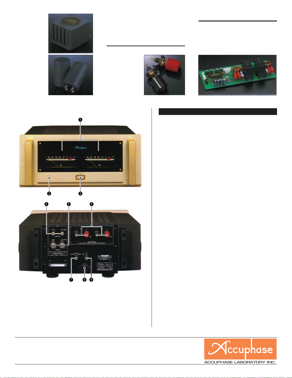
n FRONT PANEL
nn
nn
n REAR PANEL
nn
H
1 P ower meters f or left aand right channel
(dB scale)
2 Meter operation/illumination switch
ON OFF
3 P ower switch
4 Unbalanced inputs
5 Balanced input connectors
a Ground b Inverted (–)
c Non-inverted (+)
Remarks
H
This product is available in versions for 120/230 V AC. Make sure that the voltage shown on the rear panel matches the AC line voltage in your area.
H
The shape of the AC inlet and plug of the supplied power cord depends on the voltage rating and destination country.
❇ Specifications and design subject to change without notice for improvements.
6 Speaker output terminals for left and right
channel
7 Mode selector
DUAL MONO NORMAL BRIDGE
8 AC input connector
(for supplied power cord)
9 Input selector
UNBAL BAL
The oversize speaker terminals accept also very
heavy-gauge speaker
cable. The terminals
are made of extruded
high-purity brass
material and are gold-
plated for utmost
reliability and minimum
contact resistance.
Molded caps provide
proper insulation.
(Guaranteed specifications are measured according to EIA standard RS-490.)
mm
m Continuous Average Output (20 to 20,000 Hz)
mm
Stereo mode ,0650 watts per channel into 1 ohms*
(both channels driven) ,0400 watts per channel into 2 ohms
Monophonic mode 1,300 watts into 2 ohms*
(bridge connection) ,0800 watts into 4 ohms
mm
m Total Harmonic Distortion
mm
Stereo mode (both channels driven)
Monophonic operation (bridged connection)
mm
m Intermodulation Distortion 0.003%
mm
mm
m Frequency Response At rated output: 20 - 20,000 Hz +0, –0.2 dB
mm
mm
m Gain 28.0 dB (in stereo and monophonic operation)
mm
mm
m Output Load Impedance Stereo operation: 2 to 16 ohms
mm
mm
m Damping Factor 270 (stereo/monophonic operation)
mm
mm
m Input Sensitivity (with an 8-ohm load) Stereo mode 1.12 V for rated output
mm
mm
m Input Impedance Balanced: 40 kilohms
mm
mm
m Signal-to-Noise Ratio 120 dB (rated continuous average output)
mm
(A-weighted, input shorted)
mm
m Output Level Meters –50 dB to +3 dB, logarithmic scale,
mm
mm
m Power Requirements 120V/230V (Voltage as indicated on rear panel)
mm
mm
m Power Consumption 80 watts idle
mm
mm
m Maximum Dimensions Width: 475 mm (18-11/16")
H
mm
mm
m Weight 38 kg (83.8 lbs.) net
mm
Large direct-reading analog power meters
The large analog power meters cover a wide
dynamic range and provide direct readings.
Switches for meter on/off and illumination control
are also provided.
Assembly with protection circuitry, etc.
P-650 Guaranteed Specifications
,0200 watts per channel into 4 ohms
,0100 watts per channel into 8 ohms
Note: Ratings marked
,0400 watts into 8 ohms
Note: Ratings marked
0.05% with 2-ohm load
0.02% with 4- to 16-ohm load
0.02% with 4- to 16-ohm load
At 1 watt output: 0.5 - 160,000 Hz +0, –3.0 dB
Monophonic operation: 4 to 16 ohms
H
With music signals, load impedance of 1 ohm (stereo)
or 2 ohms (mono) can be driven.
Monophonic mode
Unbalanced: 20 kilohms
OFF switch provided
AC, 50/60Hz
625 watts in accordance with IEC-65
Height: 223 mm (8-3/4")
Depth: 491 mm (16-1/2")
48 kg (105.8 lbs.) in shipping carton.
H
are for music signals only.
H
are for music signals only.
0.11 V for 1 watt output
2.25 V for rated output
0.11 V for 1 watt output
http://www.accuphase.com/
PRINTED IN JAPAN F0010 851-0168-00 (AD1)
 Loading...