

Accuphase STEREO POWER AMPLIFIER
- 6-parallel push-pull circuitry 250W × 2 (8 ohms) Low impedance speaker can be fully driven
- DC servo direct coupled throughout Built-in bridge connection circuit XLR connectors (balanced input) provided
All-stage push-pull circuitry. DC servo direct coupled throughout. 6-parallel push-pull power stages guarantee stereo = 250W/ch (8 oh By using the low impedance setting, even an extreme low impedance
Any program source, no matter how meticulously improved, would be useless without the reproduction system being upgraded. Now in a real digital audio age, a basic review of the characteristics of reproduction systems is required. In this sense, resolving the weakpoints of audio systems and further improving the sound field characteristics including setting and sound propagation characteristics are the current requisites to instil life not only in the new program sources but in your existing sources.
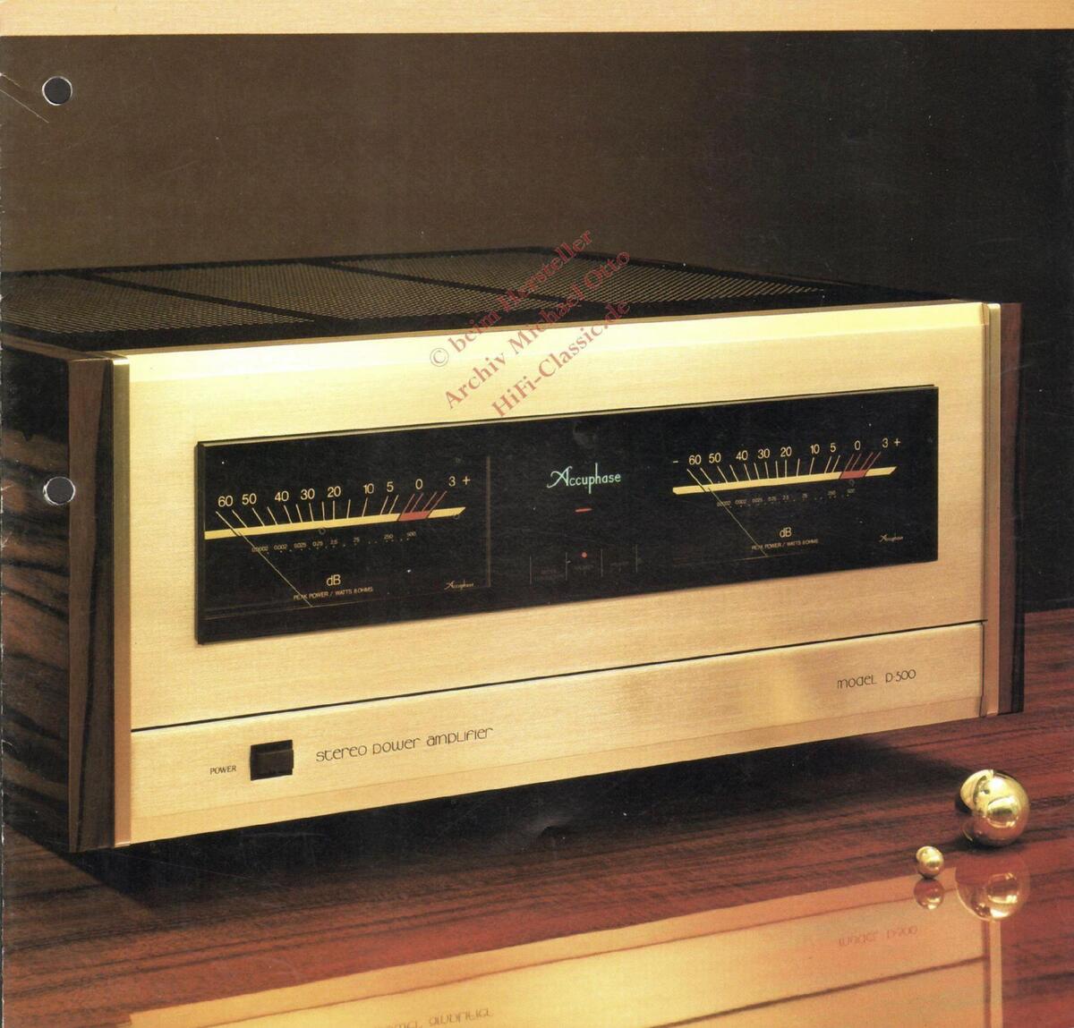
Created as a reliable means for a new audio era, the Accuphase P-500 is a stereo power amplifier that provides a lucid and emotional good music reproduction
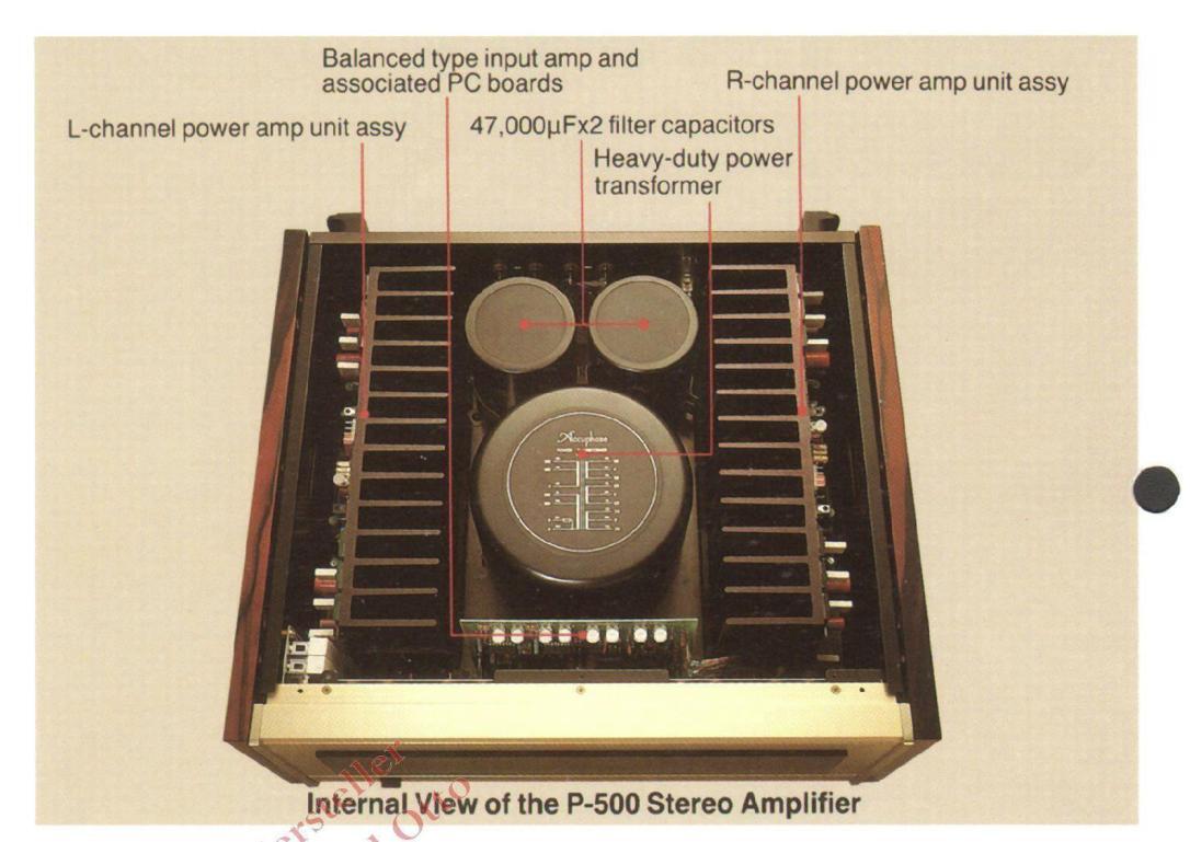
The power amplifier must excel in frequency characteristics, distortion, S/N ratio, and other basic parameters and have a capability and power to drive the speakers correctly with ample energy to be able to respond accurately to instant and wide-ranging signal variations. This necessitates a power supply with an ample reserve margin to provide the full energy that a powerful output circuit driven by a large current capacity driver stage requires. Thus, the amplifier ensures sufficient power output of 250 W/ch at 8-ohm load (20 to 20,000Hz, distortion of 0.01%) and 500 W/ch, at 2-ohm load. The Accuphase P-500, based on a heavy-duty troidal transformer affording maximum power capacity as high as 1200 VA, has a total of 12 bipolar power transistors, each with a superior wideband characteristic and maximum power dissipation (Pc) of 150 watts, that form a 6-parallel push-pull low-impedance output stage.
Especially, the low impedance setting capable of driving 2-ohm load makes it possible to supply linearly a sufficient energy to the speakers where impedance changes instantly, allowing the music dynamism to be reproduced with sheer perfection. The built-in Bridge Circuit permits the P-500 to be used as a high-quality large output monophonic amplifier that can deliver 840 W at 8 ohms and 1,000 W at 4 ohms.
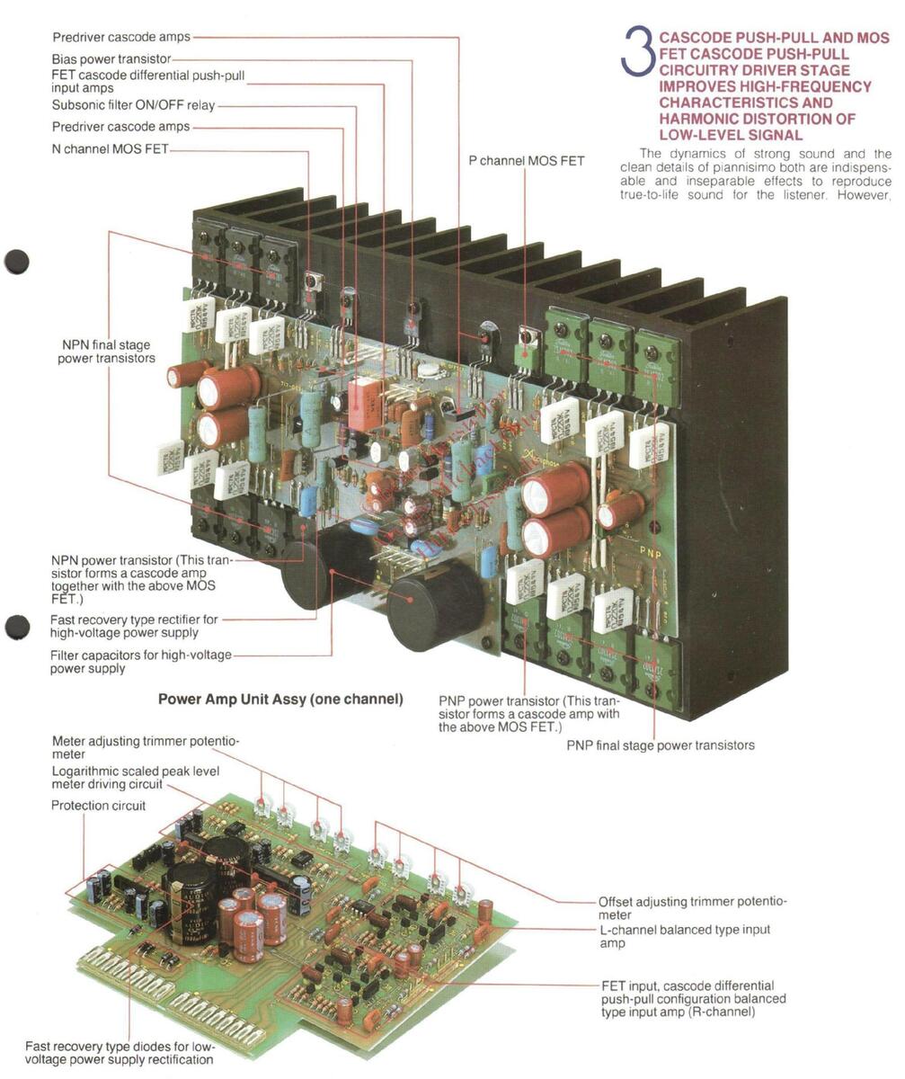
In addition to Accuphase's traditional use of cascode push-pull circuits in every stage, the driver stage of the P-500 is especially made up of Class-A push-pull circuits featuring excellent high-frequency characteristics. The employment of Class-A push-pull amplifiers in this way and of MOS FETs to drive them guarantees high sound quality of low level input signals.
To shut off the signal cable between preamplifier and power amplifier from external noise disturbance, the P-500 is equipped with highquality balanced XLR type input connectors, enabling its connection to an Accuphase preamplifier C-280 or C-200L, graphic equalizer G-18, or a professional mixing console provided with balanced type output connectors.
The P-500 has a simple layout, a combination of natural wood sideboards and a panel colored in Accuphase's traditional champagne gold with scratch hair line finish. The points emphasized in design are serenity, simplicity, and warmth.
AMPLE POWER OUTPUT GUARANTEES HIGH-QUALITY REPRODUCTION; 250 W/ch AT 8 OHMS, AND 500 W/ch AT 2 OHMS
Ordinary listening power is about 5 to 10 W when using standard speakers having an output sound pressure level of about 92 dB/w/m. In some cases, however, the level of pulse signals may frequently exceed 10 dB. The higher the maximum output of power amplifier, the higher the drive fidelity of the speakers.
This effect is indispensable for stable energy supply to speakers irrespective of instantly changing signal variations even at low output power. This resembles the fact that a car with large engine displacement runs stably even at low engine rotational speed and also gives smooth acceleration response. That is to say, a large output is necessary not only for louder volume but also for high-quality sound reproduction
P-500 has realized a maximum output a high as 250 W/ch (at 8-ohm load, 20 to 20,000Hz, and distortion of 0.01%) which may seem too luxurious for a living-room power amplifier. It is also capable of supplying large energy as high as 500 W/ch at the low impedance of 2-ohm load when used as a monophonic amplifier
To guarantee such high power output, it has a total of 12 bipolar power transistors per
channel, each with a maximum power dissipation (Pc) of 150 W, that form a 6-parallel push-pull output circuitry, as shown in Fig. 1. This circuitry has a theoretically critical output of 4,200 W at a power efficiency of 70% at the output stage and ensures an ample margin even when the amplifier is used at its rated maximum output.
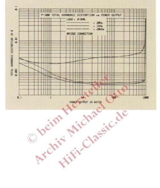
2 BRIDGE CONNECTION PERMITS PURE MONOPHONIC OPERATION WITH 840 WATTS AT 8 OHMS AND 1,000 WATTS AT 4 OHMS
If each power amplifier of the P-500 is take as a single device and used together respectively with a bridge connection as a push-pull monophonic driver, a very large monophonic power output can be obtained. This connection is called bridge connection or BTL connection. With the bridge connection, output power can be considerably increased. Another advantage of push-pull operation is improved characteristics due to the elimination of harmonic distortion as even-number harmonics are canceled out. Bridging the two channels provides a monophonic power output of 840 Watts at 8 ohms and 1,000 Watts at 4 ohms, enabling good music reproduction with an opulent sound.
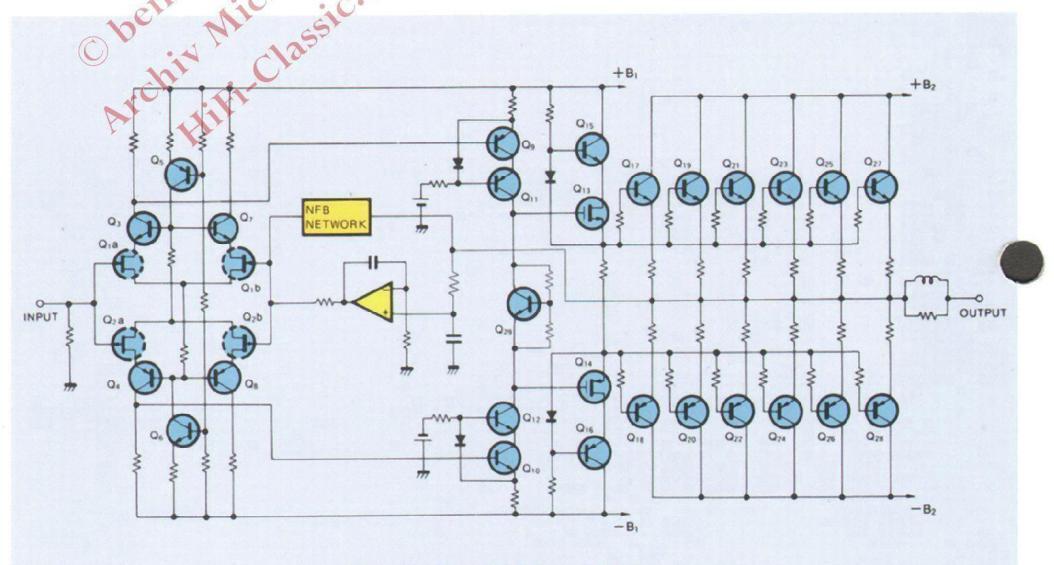
Fig. 1 P-500 Circuit Diagram
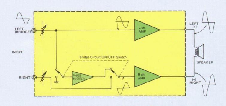
Fig. 2 Principle of the Bridge Connection
ms), monophonic = 840W (8 ohms). speaker of 2 ohms (stereo = 500W/ch) can be fully driven.
Accuphase P-500 STEREO POWER AMPLIFIER
especially for a high-power amplifier, it is difficult to embody these antipodal effects at the same time. Nevertheless, Accuphase's technology has made it possible to realize these effects in a single device. To dispose of the switching distortion at low output which may occur in the output stage, each of the PNP and NPN elements is set strictly to the operating points, avoiding cutoff (no current flow) by input signal. The predriver stage that drives the final stage of the amplifier circuit employs an arrangement of MOS FETs equivalent to nonswitching class A driver circuit and comprises cascode push-pull circuitry providing the utmost performance available at present. Moreover, the preceding stage that inputs signals to the MOS-FET driver stage forms also a class-A cascode push-pull circuitry. This results in a low distortion output stage that operates stably under any load from the low output signal range (that is affected by noise) to the high output signal range at the rated output.
CASCODE BOOTSTRAP PUSH-PULL DIFFERENTIAL AMPLIFIER INPUT STAGE RADICALLY IMPROVES THE BASIC CHARACTERISTICS WITHIN NEGATIVE FEEDBACK LOOP
Transistors Q1 through Q8 in Fig. 1 constitute a cascode bootstrap push-pull circuit as an input circuit. A cascode bootstrap circuit satisfies all the requirements of an input circuit: high gain excellent high-frequency characteristics, and no deterioration of harmonic distortion even when the input impedance varies.
For perfection of the high performance of a cascode bootstrap circuit, that of the P-500 includes a push-pull circuit. Together with the wide-band driver stage, the basic characteristics within the negative feedback loop is radically improved.
5 DIRECT COUPLED AMPLIFIER EMPLOYING DC SERVO CONTROL CIRCUITRY
The input signals to the P-500 is directly coupled to the INPUT terminal shown in Fig. 1. Therefore, when a preamplifier with a large DC (direct current) drift is connected, the DC components in the input signal is amplified and contained in the output signal. This possibly results in damage to the speakers. the P-500 has a DC Servo Control circuit, an original by Accuphase, to block such DC components and at the same time to stabilize the DC drift of the amplifier caused by temperature fluctuation.
5 BALANCED 3P XLR (cannon) TYPE INPUT CONNECTORS ENABLE SIGNAL TRANSMISSION FREE FROM EXTERNAL INDUCTIVE NOISE
Besides the conventional unbalanced input connectors (phono jacks) of 20k ohms, the P-500 is equipped with balanced 40k ohms input connectors. By using the internationally applicable 3P XLR (cannon) type connectors, the balanced output of any impedance can be connected.
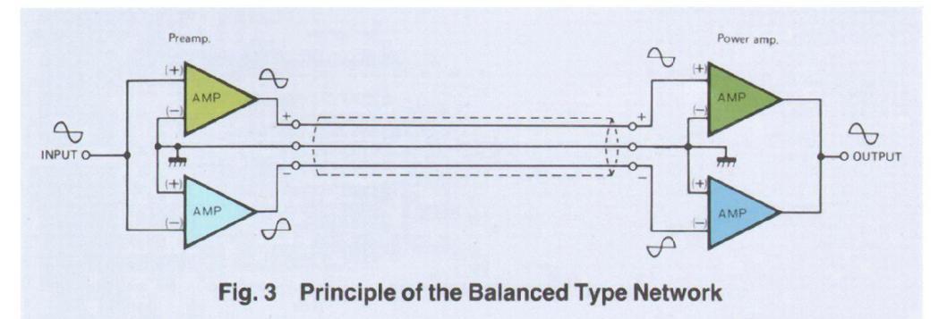
The principle is shown in Figure 3 in which equal positive and negative signal voltages in relation to ground potential are transmitted by the balanced cable network. Even if unwanted noise disturbances happen to be picked up by the cable, the positive and negative noise signals will appear in the same phase at the input of the differential amplifier where they are canceled out. Because noise components which may occur in the cables enter both poles with the same phase, it is nullified when signals are mixed in the input amplifier.
External noise disturbance which affects sound quality increases as the interconnecting cables are lengthened. The balanced type cable network completely eliminates this adverse influence, thereby ensuring highquality signal transmission.
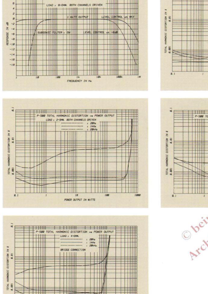
10Hz SUBSONIC FILTER WITH -18 dB/oct SLOPE
Ultra-low frequency noise below 20Hz entering the reproduction circuit causes intermodulation distortion and harms sound quality. The P-500 is equipped with a subsonic filter that cuts off harmful extremely low frequency below 10Hz, to protect speakers from damage. Highquality elements completely eliminate degradation of sound quality and its frequency setting does not affect the audible frequency range Always use the P-500 with the subsonic filter switch set to on.
B EASY-TO-READ ANALOG TYPE POWER LEVEL METERS ALLOW DIRECT READING OF -60 to +3 dB RANGING OUTPUTS
The P-500 is equipped with a pair of analog type power level meters with both dB and wattage scales that allow direct reading of output power levels. The logarithmic scaled power level meters permit direct reading of output power ranging as wide as -60 (0.00025W/8 ohms) to +3 dB (500W/8 ohms). The P-500 is also provided with a switch to turn on or off the meter operations and illumination lamps.
ELEGANTLY SIMPLE DESIGN OF FRONT SUBPANEL
As shown in the photograph of the P-500 power amplifier (front view), none of the function switches and controls other than the power switch is visible when the subpanel is closed. They are the L- and R-channel level controls (1 dB step, 0 to -20dB), subsonic filter ON/OFF switch, selector switch for speakers, bridge connection ON/OFF switch, meter operation ON/OFF switch, and unbalanced/balanced input selector switch.
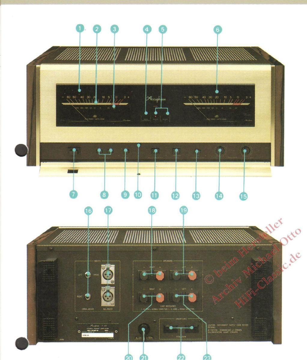
L-channel power level meter
- dB scale
- Wattage scale
- Bridge connection indicator
- SPEAKER system A and SPEAKER system B indicators
- 6 R-channel power level meter
- POWER switch
- SPEAKERS selector switch
- METER operation/light ON/OFF switch
- Magnetic catch for subpanel BRIDGE CONNECTION ON/OFF switch UNBALANCED/BALANCED input selector
- SUBSONIC FILTER ON/OFF switch
- INPUT LEVEL control (1 dB step) for L-channel
- and bridge connection INPUT LEVEL control (1 dB step) for R-channel
- INPUT jacks (UNBALANCED/20k ohms) Use the LEFT jack for bridged monophonic opera-
- 1 3P XLR (cannon) type input jacks (BALANCED/
- Speaker A R-channel output
- Speaker A L-channel output
- Speaker B R-channel output
- AC power cord
- AC outlet (UNSWITCHED)
- Speaker B L-channel output
PERFORMANCE GUARANTY
All Accuphase product specifications are guaranteed as stated
All specifications are measured in accordance with EIA measurement method RS-490. CONTINUOUS AVERAGE POWER OUTPUT:
STEREOPHONIC MODE (Both channels driven):
- EREOPHONIC MODE (Both channels driv. 500 watts/channel, min. RMS, at 2 ohms 420 watts/channel, min, RMS, at 4 ohms 250 watts/channel, min, RMS, at 8 ohms 125 watts/channel min, RMS, at 6 ohms
- MONOPHONIC MODE (Bridge Connection): 1,000 watts, min. RMS, at 4 ohms 840 watts, min. RMS, at 8 ohms 500 watts, min. RMS, at 16 ohms
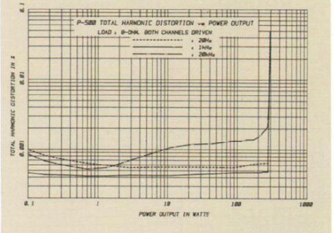
TOTAL HARMONIC DISTORTION:
000Hz at any power output from watt
- INTERMODULATION DISTORTION (SMPTE-IM):
GUARANTY SPECIFICATIONS
FREQUENCY RESPONSE:
- 20Hz to 20,000Hz, +0, -0.2dB for continuous aver-age power output at the maximum level control 0.5Hz to 300,000Hz, +0, -3.0dB for 1 watt output at the maximum level control 0.5Hz to 100,000Hz, +0, -3.0dB for 1 watt output at
- VOLTAGE AMPLIFICATION IN DECIBELS: 8.0dB at STEREOPHONIC and MONO
OUTPUT LOAD IMPEDANCE: 2 ohms to 16 ohms at STEREOPHONIC MODE 4 ohms to 16 ohms at MONOPHONIC MODE (Bridge
DAMPING FACTOR (50Hz)
DAMPING FACTOR (50Hz): 500 at STEREOPHONIC MODE 250 at MONOPHONIC MODE (Bridge Connection)
INPUT SENSITIVITY AND IMPEDANCE
(at 8 ohms load): STEREOPHONIC MODE: 1.78V for continuous average power output at the
MONOPHONIC MODE (Bridge Connection): 3.26V for continuous average power output at the maximum level control
20k ohms UNBALANCED input and 40k ohms BA-LANCED input
- A-WEIGHTED SIGNAL-TO-NOISE RATIO: (STEREOPHONIC AND MONOPHONIC MODES)
- SUBSONIC FILTER:
- thmic scaled type -60 to +3dB range direct
- SEMICONDUCTOR COMPLEMENT:
- POWER REQUIREMENT:
Voltage selection by rewiring for 100V, 117V, 220V, and 240V, 50/60Hz operation
- DIMENSIONS:
- DIMENSIONS: 480mm (18-15/16 inches) width, 218mm (8-10/16 inches) max. height, 445mm (17-1/2by inches) depth WEIGHT:
- 33.5kg (73.7 lb) net, 40kg (88.0 lb) in shipping carton


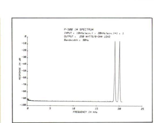
The above data shows the spectrums of IHF intermodulation distortion for the P-500 as measured by the EIA measurement method. Amplitudes of 1 kHz and 20 kHz input signals are shown on the right of the figure. Any intermodulation created by these two signals would appear as spectrum peaks at 1 kHz intervals, the frequency difference between the two signals, across the frequency bandwidth. This data shows them to be hardly noticeable, confirming that IM distortion is less than -93 dB (0.0022%).
Another form of IM distortion would appear at 39 kHz, the sum of the two input signal frequencies 19+20=39 kHz). Such a distortion, even if it existed, would be inconsequential because it is far beyond the audible range. In the P-500, this form of IM distortion is also less than -93 dB.

The above data shows the spectrum characteristics of transient intermodulation distortion for the P-500 when two mixed input signals, a 3.18 kHz square wave and a 15 kHz sine wave, are used. Since harmonics of square waves appear almost infinitely at odd-number multiples, for example in this case at 9.54 kHz (3rd harmonic) and 15.9 kHz (5th harmonic), they can create, together with the 15 kHz input sine wave, intermodulated spectrums at frequencies where input signals are absent. For example, if the third harmonic of the 3.18 kHz square wave (9.54 kHz) and the 15 kHz input signal intermodulate, a spectrum can appear at the difference of their frequencies, or 5.46 kHz (15–9.54=5.46 kHz). However, the above data shows no spectrum above –93 dB at that frequency. This confirms that TIM distortion is less than 0.0022%.
ccuphase
Accuphase P-500 STEREO POWER AMPLIFIER


 Loading...