

Page 1
m 3-parallel push-pull output stage delivers linear power into
ultra-low impedance loads m Current f eedback circuit topology
combines excellent sound quality with total operation stability
m Br idged connection mode allows upgrading to true
monophonic amplifier m Massive Super Ring toroidal transf ormer
m Balanced inputs m Two sets of large speaker connectors
Page 2
The embodiment of musical power. Witness a stereo power amplifier
capable of delivering 400 watts of linear power into 1-ohm loads. Current
feedback topology guarantees stable operation up to ultra high
frequencies. Massive power supply with 700 VA toroidal transformer,
and wide-band high-power transistors in 3-parallel push-pull
configuration ensure constant-voltage drive.
In order for an amplifier to drive loudspeakers
to optimum performance, two major goals must
be realized: very low output impedance (Note
1), and constant drive voltage (Note 2). Low
impedance not only ensures accurate speaker
drive but also absorbs the counterelectromotive
force generated by the voice coil, thereby
eliminating a major source of intermodulation
distortion. Accuphase amplifiers are capable of
driving any kind of speaker load with optimum
results, which is one of the reasons behind the
high praise that these products invariably
receive.
The P-370 is a stereo power amplifier which
fully implements these advanced circuit design
principles. The output stage uses three pairs of
high-power transistors in each channel,
arranged in a parallel push-pull configuration.
These devices are mounted to massive heat
sinks, for efficient dissipation of thermal energy .
Power linearity is maintained down to extremely
low load impedances. This allows the amplifier
to easily drive even speakers with very low
impedance or uneven impedance curves . Using
the P-370 in bridged mode creates a mono
amplifier with even more impressive power
reserves.
The power supply section which acts as the
energy source for the amplifier employs a highefficiency "Super Ring" toroidal transformer in
combination with large filtering capacitors.
Current feedback topology combines total
operation stability with excellent frequency
response, while requiring only minimal amounts
of negative feedbac k. Balanced inputs mak e the
amplifier impervious to externally induced noise
during signal transmission. The front panel
features two large analog power meters which
give the amplifier an elegant look. For use in an
audiovisual system, the meter lights can be
switched off so as not to interfere with the
monitor image.
BIAS STABILIZER CIRCUIT
–
INPUT
+
INPUT
Note 1: Low amplifier output impedance
When forming the load of a power amplifier a loudspeaker generates a
counterelectromotive force that can flow back into the amplifier via the NF
loop. This phenomenon is influenced by fluctuations in speaker impedance,
and interferes with the drive performance of the output circuitry. The internal
impedance of a power amplifier should therefore be made as low as possible
by using output devices with high current capability.
Note 2: Constant drive voltage principle
Even when the impedance of a load fluctuates drastically, the ideal power
amplifier should deliver a constant voltage signal to the load. When the
supplied voltage remains constant for any impedance, output power will be
inversely proportional to the impedance of the load. A conventional amplifier
can be easily made to operate in this way down to a load impedance of
about 4 ohms. Howe ver , at 2 ohms and below , much more substantial output
reserves are needed. This can only be achieved by a thorough redesign of
all basic amplifier aspects.
Triple-parallel power units with push-pull
configuration deliver ample linear power:
300 watts per channel into 2 ohms, 150 watts
into 4 ohms, or 75 watts into 8 ohms
The output stage uses high power transistors
with excellent linearity and switching
characteristics, rated for a collector dissipation
of 150 watts and collector current of 15 amperes.
These transistors are arranged in a 3-parallel
push-pull configuration (Figure 1) and mounted
on massive heat sinks, for efficient heat
dissipation. This enables the P-370 to
effortlessly drive even speakers with extremely
low impedance or with reactive loads.
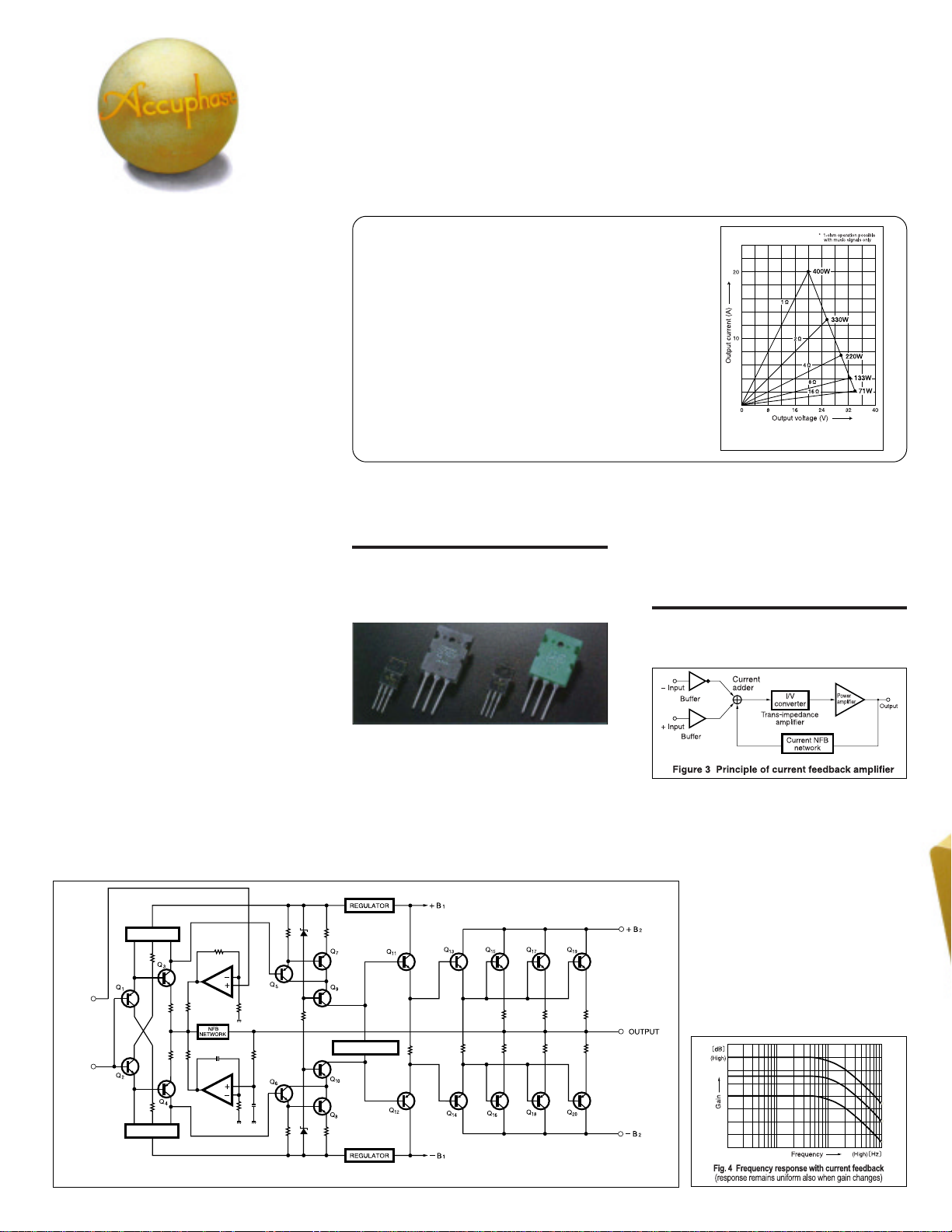
Figure 2 shows the output/voltage
characteristics at various load impedances. It
can be seen that output voltage remains nearly
BIAS STABILIZER CIRCUIT
Figure 2 Load impedance vs. output power
(output voltage/output current) of P-370
constant regardless of load, which means that
output current increases linearly. The actually
measured clipping power is an impressive 400
watts into 1 ohm, 330 watts into 2 ohms, 220
watts into 4 ohms, or 133 watts into 8 ohms.
Current feedback circuit topology prevents
phase shifts
The P-370 employs the so-called current
feedback principle. Figure 3 shows the operating
principle of this circuit. At the sensing point of
the feedback loop, the impedance is kept low
and current detection is performed. An
impedance-converting amplifier then converts
the current into a voltage to be used as the
feedback signal. Since the impedance at the
current feedback point (current adder in
Figure 3) is very low, there is almost no
phase shift. Phase compensation can
be kept to a minimum, resulting in
excellent transient response and superb
sonic transparency.
Figure 4 shows frequency response for
different gain settings of the current
feedback amplifier. The graphs
demonstrate that response remains
uniform over a wide range.
BIAS STABILIZER CIRCUIT
Figure 1 Circuit diagram of amplifier section (one channel)
Page 3

Robust power supply with "Super Ring"
toroidal transformer and high filtering
capacity
The P-370 features
a large toroidal
power transformer
with a rating of
about 700 VA. The
transformer is
housed in an
enclosure filled
with a material that
transmits heat and
absorbs vibrations. A toroidal transformer uses
heavy-gauge
copper wiring on a
doughnut-shaped
core. This results in
low impedance
and high efficiency ,
while allowing
compact
dimensions. In
particular, the
"Super Ring" transformer used in the P-370 has
various advantages, such as the near-circular
core caliber, allowing near-circular coil windings
with high packing density.
T wo ultra-large aluminum electrolytic capacitors
rated for 47,000 uF each serve to smooth out
the pulsating direct current from the rectifier,
providing more than ample filtering capacity.
Balanced connection reliably blocks induced
noise
Balanced
signal
transmission
means that
two signal
lines are used
which carry
the same
signal with
opposite
phase. On the
receiving side,
the signals are
mixed, which
Unbalanced and balanced input
connectors
cancels out
any noise, leaving only the pure original signal.
Bridged mode creates a true monophonic
amplifier with 600 watts into 4 ohms or 300
watts into 8 ohms
Bridged operation means that two amplifiers are
driven by the same signal voltage but with
opposite phase. This turns the unit into a highgrade monaural amplifier with even higher
output capability.
n Output stage of one channel with
3-parallel push-pull transistors
mounted directly to large heat
sinks. Power amplifier assembly
with current feedback amplifier
circuitry.
Page 4

Large direct-reading analog power meters
Power levels can be easily monitored thanks to
the large analog power meters which cover a
wide dynamic range and provide direct readings.
Switches for meter on/off and illumination
control are also provided.
Easy switching between dual mono
operation and bridged connection
A mode selector on the
rear panel makes it
simple to switch
between dual mono,
stereo, or bridged
operation. The dual
mono position is useful
for example to drive a center woofer in mono,
or to obtain the same signal from both speaker
outputs for driving a bi-amped speaker setup.
Two sets of speaker outputs
The large speaker
terminals accept
heavy-gauge
speaker cable. Two
sets of outputs with
an A/B speaker
selector are
provided. Both
outputs can also be
used at the same
time, which allows bi-wiring (supplying the same
signal via dual leads to speakers with separate
high-frequency and low-frequency inputs).
High-quality, high-reliability parts used in
P-370
Assembly with protection circuitry, etc.
n FRONT PANEL
(Guaranteed specifications are measured according to EIA standard RS-490.)
m Continuous Average Output (20 to 20,000 Hz)
Stereo mode 400 watts per channel into 1 ohms
(both channels driven) 300 watts per channel into 2 ohms
Monophonic mode 800 watts into 2 ohms
(bridge connection) 600 watts into 4 ohms
m Total Harmonic Distortion
Stereo mode (both channels driven)
Monophonic operation (bridged connection)
n REAR PANEL
m Intermodulation Distortion 0.003%
m Frequency Response At rated output: 20 - 20,000 Hz +0, –0.2 dB
m Gain 28.0 dB (in stereo and monophonic operation)
m Output Load Impedance Stereo operation: 2 to 16 ohms
m Damping Factor 200 (stereo/monophonic operation)
m Input Sensitivity Stereo mode 0.98 V for rated output
(with an 8-ohm load) 0.11 V for 1 watt output
m Input Impedance Balanced: 40 kilohms
★
m Signal-to-Noise Ratio 120 dB (rated continuous average output)
(A-weighted, input shorted)
m Output Level Meters –50 dB to +3 dB, logarithmic scale,
1 Power meters f or left and right channel
(dB scale)
2 Meter operation/illumination switch
ON OFF
3 SPEAKER A/B switches
4 Power s witch
5 Unbalanced inputs
6 Balanced input connectors
7 Speaker output terminals for left and right
channel
8 Mode selector
DUAL MONO NORMAL BRIDGE
9 Input selector
UNBAL BAL
J AC input connector
(for supplied power cord)
★
m Power Requirements 120V/230V (Voltage as indicated on rear panel)
m Power Consumption 44 watts idle
m Maximum Dimensions Width: 475 mm (18-11/16")
a Ground b Inverted (–)
c Non-inverted (+)
Remarks
★
This product is available in versions for 120/230 V AC. Make sure that the voltage shown on the rear panel matches the AC line voltage in your area.
★
The shape of the AC inlet and plug of the supplied power cord depends on the voltage rating and destination country.
Supplied accessory: • AC power cord
m Weight 24.4 kg (53.8 lbs) net
P-370 Guaranteed Specifications
150 watts per channel into 4 ohms
75 watts per channel into 8 ohms
Note: Ratings marked ★ are for music signals only.
300 watts into 8 ohms
Note: Ratings marked ★ are for music signals only.
0.05% with 2-ohm load
0.02% with 4- to 16-ohm load
0.02% with 4- to 16-ohm load
At 1 w att output: 0.5 - 160,000 Hz +0, –3.0 dB
Monophonic operation: 4 to 16 ohms
★ With music signals , load impedance of 1 ohm (stereo)
or 2 ohms (mono) can be driven.
Monophonic mode
Unbalanced: 20 kilohms
OFF switch provided
AC, 50/60Hz
475 watts in accordance with IEC-65
335 watts at rated power output into 8 ohms
Height: 180 mm (7-1/16")
Depth: 417 mm (16-7/16")
29.0 kg (63.9 lbs) in shipping carton
1.95 V for rated output
0.11 V for 1 watt output
★
★
• Specifications and design subject to change without notice for improvements.
http://www.accuphase.com/
PRINTED IN JAPAN C015Y 851-0115-00 (AD1)
 Loading...