


• 7-Parallel Push-Pull Output Stage 200W×2 into 8Ω • Designed to Correspond to Low Impedance Loads ● DC Servo Direct Connection System ● Used as a 600-W Monophonic Amplifier into 8Ω ● Balanced Input Incorporated Exclusive Amplifier for Headphones Incorporated

The power amplifier is, in a way, the driving unit or power source for the speakers. Therefore, power amplifiers are required to faithfully drive the speakers with great stability without being affected by the rapid fluctuation of the speakers' impedance. All of Accuphase's power amplifiers are designed to comply with such requirements. The P-360 has been developed to meet such stringent prerequisites incorporating the most advanced circuit topology and components available today.
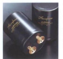
The output stage of the P-360 is equipped with 7 powerful parallel push-pull transistor pairs, that can deliver a maximum current of 210A for a period of 1/1,000 sec. as well as a powerful toroidal power transformer with a capacity of 1,000VA and a huge capacity power supply that is made up of two 40,000µF electrolytic condensers. The P-360 can, therefore, deliver a stable and ample output of 400W per channel into 2 Ohm loads, 300W per channel into 4 Ohm loads, and 200W per channel into 8 Ohm loads. When bridged, the P-360 can work as a fully balanced monophonic power amplifier that can deliver 800W into 4 Ohm loads and 600W into 8 Ohm loads.
With the aim to achieve the utmost in performance, the front stage now incorporates an extravagant circuit configuration, which consists of a high performance class-A cascode circuit and a MOS-FET cascode push-pull circuit. This circuit configuration is considered today to be the most ideal circuit topology for such an amplifier stage.
All of our products, including tuners, incorporate Accuphase's exclusive balanced signal transmission system, that features a direct input into the differential amplifier circuit at the input stage. This is ideal, because it does not require a signal-converting amplifier, which may impair audio quality.
An additional feature of the P-360 is an independent amplifier exclusively dedicated to headphone operation. This makes it possible to monitor and enjoy the highest quality music reproduction through headphones.
The P-360 is also equipped with such useful functions as front input terminals, which can be used for connecting peripheral equipment, and a speaker system selector that enables the selection of two pairs of speakers. We are confident that our latest innovation, the P-360, has successfully pursued the goal of obtaining the utmost performance as a power amplifier.
7 Powerful Parallel Push-Pull Transistor Driven Output Stage Offers Ample Power Reserves: 200 Watts per Channel into 8 Ohms, 400 Watts per Channel into 2 Ohms, and Capability to Drive Even 1 Ohm Loads
The impedance of a speaker varies widely depending on frequencies reproduced. Even if the impedance of a speaker system is rated at 8 Ohms, the actual impedance sometimes goes down to nearly 2 Ohms at certain frequencies. Therefore, the output impedance of a power
Incorporating FET Input Circuitry, All-Stage Push-Pull Circuitry, DC Servo System that Directly Connects All Audio Signal Circuits, and High Capacity Toroidal Transformer and the 7-Parallel Push-Pull Output Stage that Can Produce a Stereophonic Output of 200W per Channel and a Monophonic Output of 600W into 8Ω. Loads As Low As an Impedance of 2Ω Can be Perfectly Driven.
amplifier should be as low as possible to drive all kinds of speakers without any strain. The employment of an NFB (negative feedback) can seemingly lower the output impedance, but it does not always deliver high quality electric current. Therefore, an output circuit, that can truly deliver a large electric current is required.
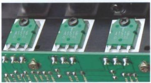
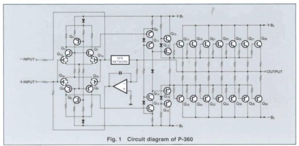
As shown in the Fig. 1, the P-360 utilizes an output transistor capable of a large electric current drain in a 7-parallel push-pull configuration, which enables the delivery of an electric current as high as 210A for 1ms (which is equivalent to a 1kHz musical signal for 1/1,000 sec.). This actually equals as much electric power as 44kW into a 1 Ohm load, which guarantees a truly phenomenal driveability.
High Power Supply Circuit Consisting of High Efficient, Large Sized Toroidal Transformer and Large Filters Capacitors
The basis of music reproduction is the faithful reproduction of low frequency sounds. To satisfactorily reproduce a substantial low frequency sound, it largely depends on the electric power supply capability of the power supply circuit. To realize this, such prerequisites must be met: the
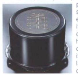
shower transformer should have a large electric power capacty and the filter condenser should have a high energy holding capability. Thanks to ts highly efficient, arge size, 1kVA toroi-
two filter condensers with a capacitance value of 40,000µF, the P-360 obtains a flat output voltage to cover the entire frequency range from 20Hz to 20,000Hz.
Class-A Cascode Push-Pull and MOS-FET Cascode Push-Pull Driver Stage Improves High Frequency Characteristics and Harmonic Distortion at Low Output Level
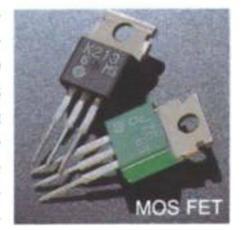
The driver stage employs Accuphase's original MOS-FET and cascode push-pull circuitry. Generally, power transistors to be used in audio power amplifiers need to amplify a wide dynamic range of audio frequencies from minute signal levels to high amplitude levels with linearity and without distortion. A push-pull circuitry is usually employed for a power amplifier stage, which consists of NPN- and PNP-type transistors, thus inevitably causing so-called switching distortion, when signals switch from one transis-
for to the other. Accur ohase's amplifiers emoloy MOS-FET's in the driver stage, which is further connected in a cascode push-pull configuration. This remark ably improves the performance characteris
ics at low signal output levels.
Moreover, the output stage employs a bipolar transistor with a positive temperature coefficient, while the driver stage employs MOS-FET's with a negative temperature coefficient, thus cancelling each other out to achieve a nighly stable power amplification. Also employed in the pre-driver stage is a class-A cascode push-pull circuitry, which additionally contributes to the stability of the MOS-FET's function.
All Amplifier Stages Direct-Coupled with DC Servo Control
The input of each amplifier stage of the P-360 is a socalled direct coupled configuration, which supplies input signals directly to every amplifier stage without any coupling capacitors in-between the stages. Although it would be ideal to implement a direct coupling down in the DC domain, it tends to become a problem, when even a bit of DC leakage from the pre-amplifier is amplified. This may be detrimental to the speaker system. The P-360 employs Accuphase's original DC servo control circuit, which effectively suppresses amplification in the DC domain and shuts out DC current. This circuit also contributes to the stable operation in case of temperature fluctuations with the help of NFB to control the output offset from the amplifier.
Ideal Balanced Differential FET Input Stage in Pure Complimentary Push-Pull Drive Configuration
As shown in the Fig. 1, the input stage employs a balanced differential pure complimentary pushpull circuit. The positive (non-inverted) and the negative (inverted) inputs are connected to a FET input buffer amplifier, which features high input impedance and excellent driveability with low output impedance. In a balanced signal connection, signals are fed directly to these inputs, thus providing high quality amplification. In case of an unbalanced signal connection, the negative input is grounded and thus only the positive signals are fed through.
In bridged operation, as shown in Fig. 4, an identical signal is input simultaneously to the positive signal path of one of the two amplifier blocks and to the negative signal path of the other. Therefore, the P-360 can perform ideal monophonic amplication without employing any
additional circuits, such as a phase inverting amplifier, which could lead to sound deterioration.
Balanced Inputs Offer Perfect Protection Against External Noise
The P-360 provides high quality 40k Ohm balanced input terminals beside standard 20k Ohm RCA type pin jacks. With an internationally standard XLR type connector, balanced input signals with various impedance values can be accepted by the P-360.
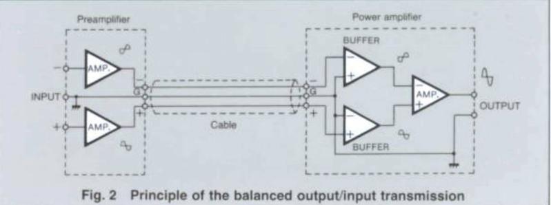
The operating principle of a balanced output to a balanced input is shown in the Fig. 2. The output side delivers the positive and negative signal outputs (with the phases 180 degree inverted) of an identical voltage. The input side mixes the two signals by receiving them at the positive and negative amplifiers. External noise collected through the inter-connect cables can be cancelled out, when mixed in the input amplifiers, as the noise contents are fed to both sides of the inputs with the same polarity. The
longer the audio cable is, the more the external noise interference tends to increase, and thus deteriorating sound quality. The balanced connections ensure perfect cancellation of such external noise.
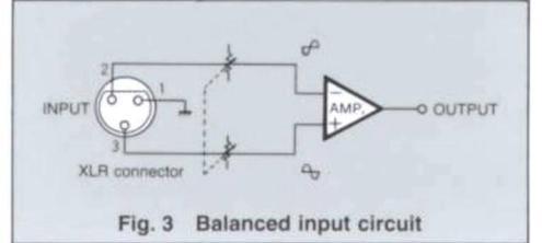
The balanced input stage of the P-360 features an ideal circuit topology, which supplies signals directly to the positive and negative inputs of the differential input circuit as shown in the Fig. 3. Because of this, a level control must be inserted at both the positive and negative inputs. However, the P-360 employs high-precision 1dB step double-ganged attenuators with superior tracking ability. Thanks to the superior design of the input circuit, the frequency response is not effected by the position of the level controls.
Bridged Operation Creates a Monophonic Power Amplifier with an Output of 600 Watts into 8 Ohm and 800 Watts into 4 Ohm Loads
In a bridged connection, as shown in the Fig. 4, an identical signal with opposite phase is fed into the same amplifier to obtain twice the output as in stereophonic operation into 4 Ohms. In a conventional bridged connection, this can only be realized by adding a phase inverting circuit to either one of the stereo channels.
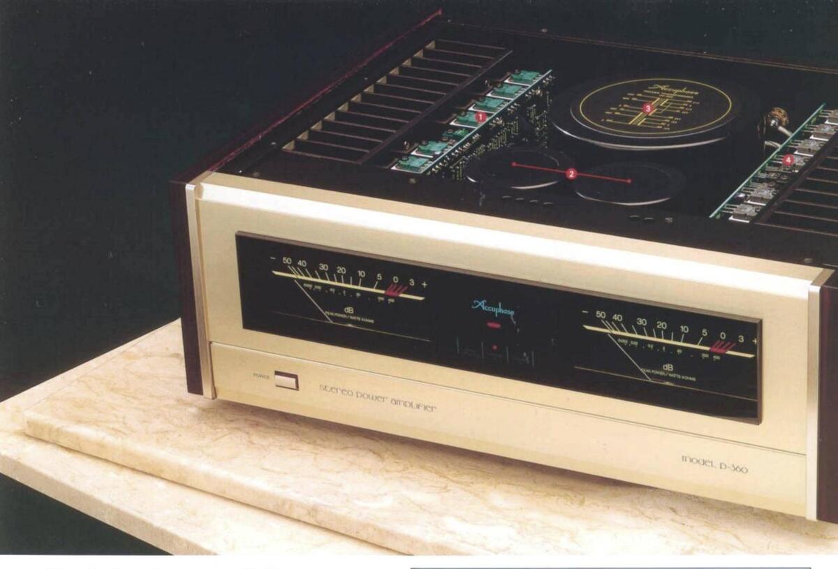
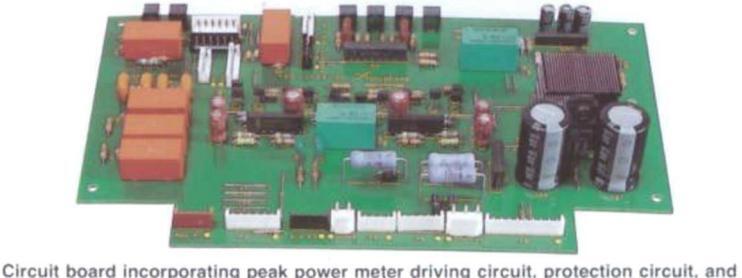
AMPLIFIER UNIT (each channel) The 7-parallel output stage and amplifier circuitry mounted to a large heat sink.
- PNP output transistors of the 7-parallel push-pull circuitry NPN transistor for the class A cascode predriver
- Ine cascode driving stage incorporating P-channel MO FET and transistor
- Resisters connected to the emitter of the final transisto
- Phase correction circuit
- Power supply for the driver
- Differential input buffer amplifier un
- Differential complementary push-pull amplifier units
INTERIOR LAYOUT
- Left channel amplifier unit
- Large toroidal power transforme
- Right channel amplifier unit
additives, such as grease, that tends to deteriorate sound quality, is applied between the collectors and the resistors. Standard type variable resistors have rotating collectors and the resistors connected to external terminals with leads going through rivet holes. The attenuators employed in the P-360 instead have rotating resistors and fixed collectors that are connected directly to the external terminals. This construction has successfully reduced the number of metal joints from 5 to 3, thus greatly contributing to the improvement in sound.
Each channel uses an independent doubleganged type attenuator for the positive and negative signal paths. Being able to be adjusted in 1-dB increments, it guarantees precise control of the input level.

High Audio Quality Exclusive FET Headphone Amplifier
Provided in the P-360 is an independent FET type servo controlled amplifier exclusively dedicated to headphone operation. This ensures high quality sound reproduction and the elimination of any influence to the main circuitry. A
separate volume control is provided for the headphone amplifier, so that it can control the output level independently from the volume level of the speakers.
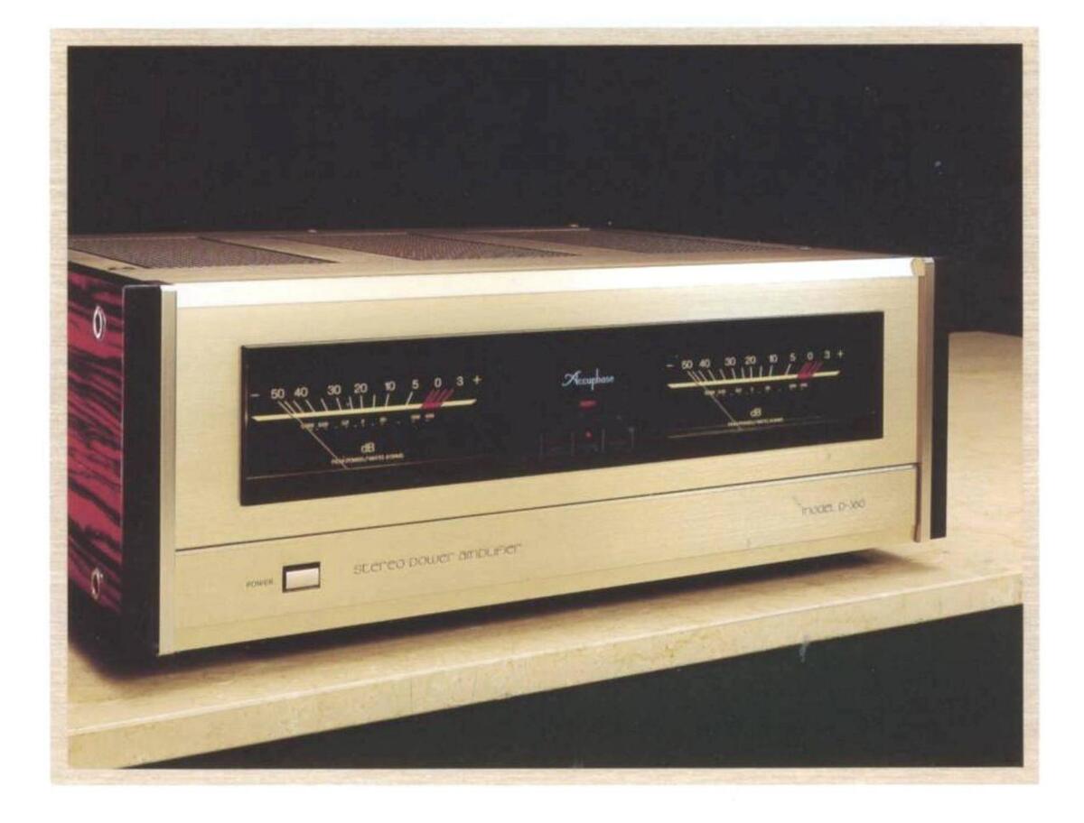
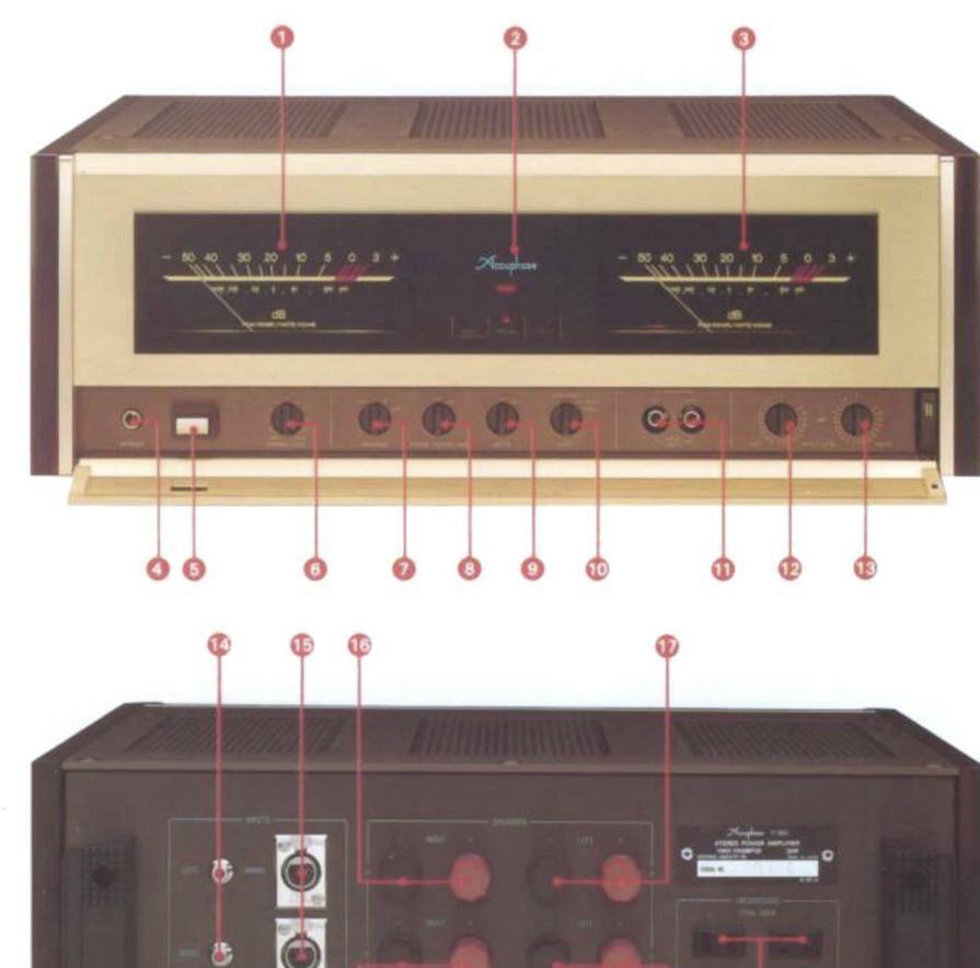
Peak Power Meters Show Direct Level Readings in dB and Watts
The logarithmic scale type peak indicators provide the readings of a wide output range extending from -50dB through +3dB and indicate the direct output power into an 8 Ohm load. The peak power meters and the illumination can be switched off if so desired.
Three Input Systems Including Front Panel Input Jacks
The P-360 provides one pair of balanced as well as two pairs of unbalanced input connections, which can be selected with a switch behind the ninged front sub-panel. One pair of unbalanced nputs is located directly behind the sub-panel, making it convenient for the connection of peripheral devices.
Bi-Wired Speakers or Two Speaker Systems Can be Connected
Two pairs of speakers connected to the speaker terminals may be driven either separately or simultaneously. Speaker systems, that are provided with bi-wiring possibilities (separate terminals for low, medium and high frequency speaker units) can be connected to the P-360.
Natural Persimmon Side Panels
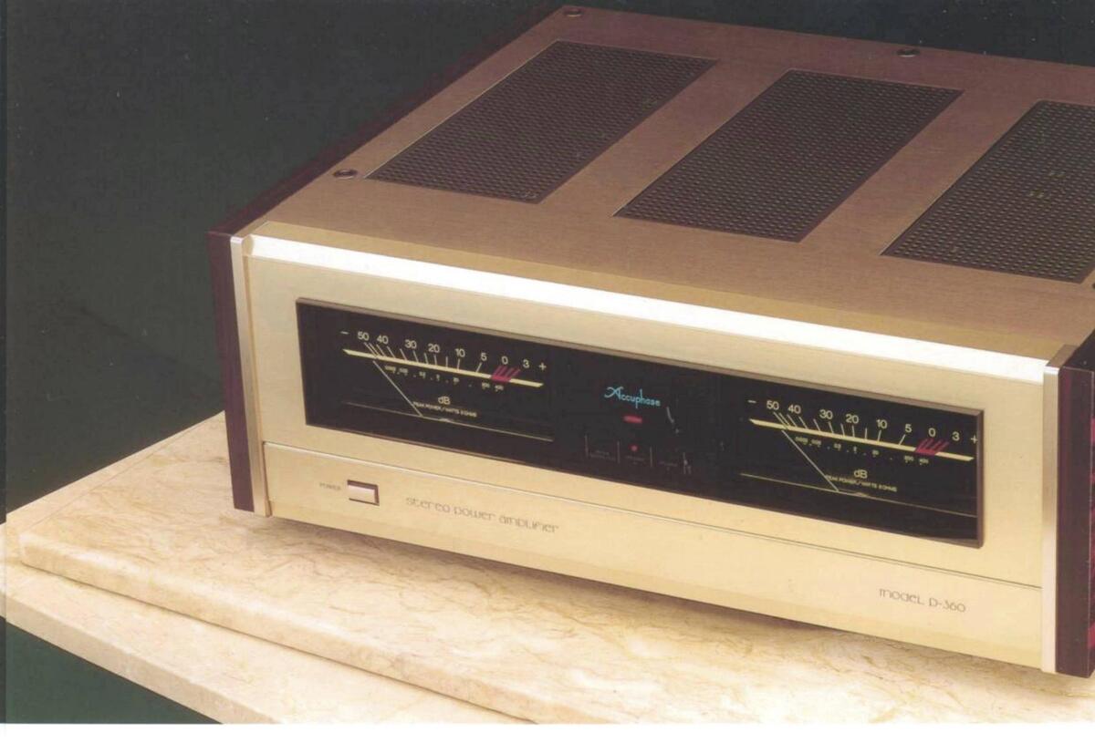
Except for the power switch, all function switches are located behind the hinged sub panel in the lower section of the front panel, finished in brushed champagne gold aluminum. The visual appeal of the amplifier is further enhanced by the side panels made of exquisite natural persimmon wood.
Fig. 4 Principle of the bridged connection
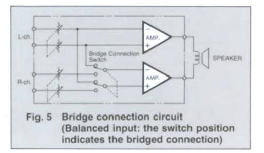
In the P-360, as shown in the Fig. 5, the polarity of the differential input circuit has both inverted and non-inverted phases. This successfully eliminates any additional circuit and constitutes an ideal bridged circuit. When bridged, the P-360 can deliver a monophonic audio output of 600W into 8 Ohms and 800W into 8 Ohms, thus providing the possibility to enjoy more enhanced musical details.
Independent Input Level Double-Ganged Attenuators can control Left and Right Audio Volume Precisely
The input level attenuators employed in the P-360 are a special low distortion type with mirrorfaced smooth resistors. This mirror-like smoothness guarantees excellent distortion characteristics and greatly reduces wear and tear. No
.
* The unswitched AC outlet may not be supplied depending on the safety standards or regulations applicable in the particular country to where the unit is destined.

enrich life through technolo
Maximum Dimensions
413mm (16-1/4°) depth • Weight 27.4kg (60.4 lbs.) net 32.5kg (71.7 lbs.) in shipping carton
GUARANTY SPECIFICATIONS
rformance Guaranty
- All Accuphase product specifications are guaranteed as stated. Continuous average power output (from 20 to 20,000Hz)
-
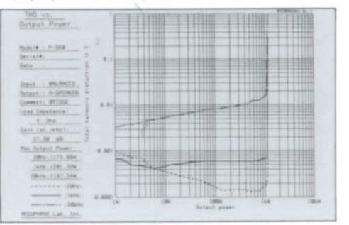
- Total harmonic distortion Stereo mode (both channels driven) 0.02% at 2 to 16Ω Monophonic mode (bridge connection) 0.02% at 4 to 16Ω
- 0.02% at 4 to 16Ω Intermodulation distortion
- Frequency response
- Frequency response 20 to 20.000Hz +0. -0.2dB (for rated output, level controls at maximum) 0.5 to 160.000Hz +0. -3.0dB
- Gain
- Gain 28.0dB (in stereo and monophonic mode) Output load impedance
- 150 in monophonic mode (bridge Input sensitivity (with 8-Ω load)
- Input impedance
- Signal-to-noise ratio (A-weighted)
- 120dB with input shorted, at rated output 100dB with 1-kΩ input, at 1W output
- Peak power meters Logarithmic scale. -50dB to +3dB range and direct watt-
- Semiconductor complement 63 transistors, 32 FETs, 10 ICs, 77 diodes
-
Voltage requirements and power consumption 100, 117, 220, and 240V, 50/60Hz 100W at zero signal input 633W at rated power output into 8Ω
| CALLS T | ||
|---|---|---|
| Output Pours | ||
| - | ||
| Derrele) | 2.1 | |
| Intro - BERNETS | ||
| Ameria Millia | 10 | |
| 8 Des | 121-1-101 | |
| 14(- (+) (000)) | ||
| Sen. Related. Press. | A | |
| 2001a 1 000.25w | 1444 - L | |
| 28010 RDL 284 | ||
| Iddae 10 | Ide Item (La | |
| NULIFATELLAR. DOL |


 Loading...