

Page 1
m Ultra-powerful output stage with 22 parallel push-pull transistors
remains linear down to extremely low 1-ohm load impedance m MCS
configuration in input stage m Stabilized power supply in driver stage
m Current feedback circuit topology assures great sound and stable
operation m Bridged use of two units possible f or f our times the output
power m Massive Super Ring toroidal transformer rated for 3 kVA max.
Page 2
When developing the M-8000, Accuphase took a fresh
look at the entire concept of the power amplifier. As a
result, the M-8000 was designed to realize the ideal
of constant voltage drive, which is best implemented
in a monophonic configuration. In order to bring out
the full performance potential of any loudspeaker,
unaffected by the often drastic fluctuations in speaker
impedance, the amplifier must have very low output
impedance (Note 1), and it must be able to supply a
constant drive voltage (Note 2).
In the M-8000, a complement of 22 output transistors
with a collector dissipation (Pc) of 150 watts each is
used in the output stage. Connected in parallel, these
devices have a combined collector dissipation of 6,600
watts. At the extremely low load impedance of 1 ohm,
the amplifier is rated to deliver an amazing 2,000 watts.
Constant voltage drive enables linear progression of
output vs. load impedance. This performance is
sustained by a massive Super Ring toroidal
transformer housed in a diecast enclosure with directly
mounted heat sinks, and by large filtering capacitors.
The transformer is rated for 1,5 kVA, max. 3,0 kVA,
and there are two capacitors of 40,000 µF each. This
assures more than ample reserves and allows the
M-8000 to meet even the most demanding and rapidly
fluctuating power requirements. Use of two units in
bridged configuration is also possible, resulting in a
mono amplifier with even higher capabilities.
The important input stage also has been given due
attention. Another Accuphase innovation called MCS
(Multiple Circuit Summing) helps to minimize noise.
The predriver stage features a DC stabilized power
supply. This results in drastically improv ed S/N ratio ,
minimum distortion, and superb performance in all
other aspects. Stable output is achieved regardless
of fluctuations on the AC side. Current feedback
topology makes it possible to combine stable
operation with impeccable frequency response. The
circuit boards of the M-8000 possess a Teflon base
with low dielectric constant and minimum loss.
Balanced inputs help to shut out external noise. T he
copper foil side of PCBs and all input and output
terminals as well as all major signal carrying points
are gold plated. The o verall result of these measures
is musical purity that leaves nothing to be desired.
* Teflon is a registered trademark of DuPont USA.
Bias stabilizer
circuit
Constant current
circuit
Bias stabilizer circuit
Bias stabilizer
circuit
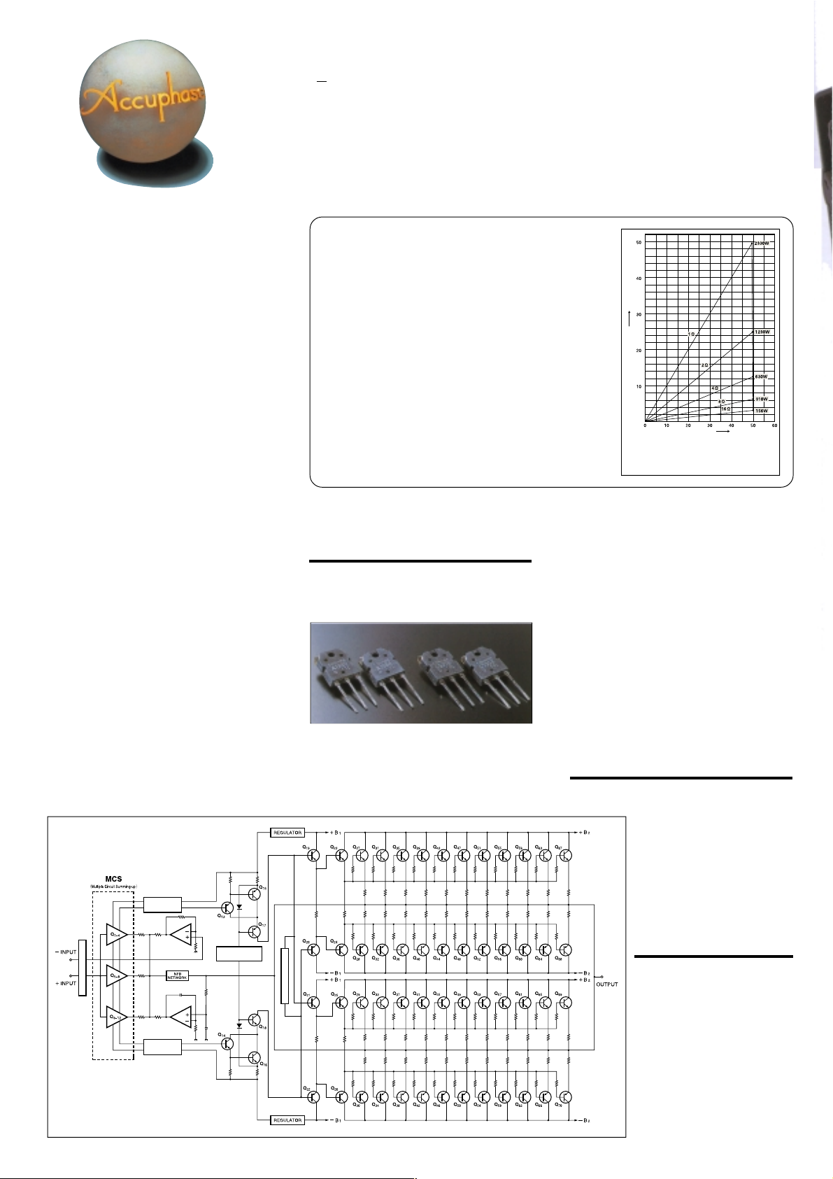
Fig. 1
Circuit diagram of amplifier section
A monophonic power amplifier with impressive muscle: 2000 watts into
1 ohm MCS topology for input stage assures high S/N ratio. 22 wide-band
high power transistors in parallel push-pull configuration. Power supply
with massive 3 kVA toroidal power transformer realizes constant voltage
speaker drive and delivers linear po wer down to impedances as low as one
ohm. Teflon PCBs with low dielectric constant and minimum loss.
Note 1: Low amplifier output impedance
When forming the load of a power amplifier a loudspeaker
generates a counterelectromotive force that can flow back into the
amplifier via the NF loop. This phenomenon is influenced by
fluctuations in speaker impedance, and interferes with the drive
performance of the output circuitry. The internal impedance of a
power amplifier should therefore be made as low as possible by
using output devices with high current capability .
Note 2: Constant drive voltage principle
Even when the impedance of a load fluctuates drastically , the ideal
power amplifier should deliver a constant voltage signal to the load.
When the supplied voltage remains constant for any impedance ,
output power will be inversely proportional to the impedance of
the load. A con ventional amplifier can be easily made to operate
in this way down to a load impedance of about 4 ohms. Howev er,
at 2 ohms and below, much more substantial output reserves are
needed. This can only be achieved by a thorough redesign of all
basic amplifier aspects.
Ultra-powerful output stage with 22 parallel pushpull transistors delivers 2,000 watts into 1 ohm,
1,000 watts into 2 ohms, 500 watts into 4 ohms
and 250 watts into 8 ohms
The M-8000 uses a complement of 22 high-power
transistors with a collector dissipation (Pc) of 150
watts and a collector current of 15 amperes each.
These devices are excellent in every regard,
including frequency response, current amplification
linearity, and switching characteristics. The 22
devices are connected in a parallel push-pull
configuration and mounted to immense heat sinks
Bias stabilizer circuit
made of diecast aluminum. This assures efficient
dissipation of thermal energy and provides plenty of
performance margin. As a result, the power amplifier
is capable of delivering enormous output power in a
linear progression towards lower load impedances:
2,000 watts into 1 ohm, 1,000 watts into 2 ohms,
500 watts into 4 ohms and 250 watts into 8 ohms.
The M-8000 also is able to drive reactive loads with
ease.
Figure 2 is a graph plotting the output voltage versus
current characteristics. Even when the load changes ,
the output voltage remains almost constant, showing
linear current progression. Actual measurement of
clipping power at the extremely low load impedance
of 1 ohm yields 2,330 watts. At 2 ohms , the figure is
1,230 watts, at 4 ohms 630 watts, and at 8 ohms
310 watts. This demonstrates the impressive
performance reserves of this amplifier.
MCS topology in input stage drastically improves
S/N ratio
The input stage features Accuphase's original MCS
(Multiple Circuit Summing) design. Three separate
Output current (A)
Output voltage (V)
* 1-ohm operation possible
Fig. 2 Output power vs. load impedance
(output voltage/output current: actual measurements)
with music signals only
unit amplifiers for the input signal are
connected in parallel, which
minimizes noise and distortion and
greatly improves other performance
parameters as well. This manifests
itself in further improved sound
quality.
Stabilized power supply in driver
stage assures outstanding
operation stability
The MCS circuitry and predriver stage
employ a DC stabilized power supply .
When the power stage amplifies a
signal to large amplitudes, this could
cause noise in the input stage via the
power supply. This is prevented by
fixing the voltage of the predriver
stage, to improve the quality of the
power supply for the low-level
amplification stages. Outstanding
S/N ratio and stable operation
unaffected by ambient temperature
and by AC line fluctuations is
guaranteed at all times.
Page 3

Current feedback circuit
topology prevents phase shifts
in high frequency range
The M-8000 employs the original
Accuphase current feedback principle.
Figure 3 shows the operating principle
of this circuit. At the sensing point of the
feedback loop, the impedance is kept low and
current detection is performed. An impedance-
Buffer
Buffer
Current adder
I-V
converter
Trans-impedance
amplifier
Current NFB
network
Amplifier
Output
– Input
+ Input
Fig. 3 Current feedback amplifier principle diagram
converting amplifier then turns the current into a
voltage to be used as the feedback signal. Since the
impedance at the current feedback point (current
adder in Figure 3) is very low, there is almost no
phase shift. Phase compensation can be kept to a
minimum,
resulting in
excellent
transient
response and
superb sonic
transparency.
Figure 4 shows
frequency
response for
Fig. 4 Frequency response with current feedback
(Response remains uniform even when gain changes)
different gain settings of the current feedback
amplifier. The graphs demonstrate that response
remains uniform over a wide range.
Use of two M-8000 in bridged configuration
possible, resulting in a mono amplifier with four
times the power
Bridged operation means that two amplifiers are
driven by the same signal voltage but with opposite
phase. The speaker load is then connected betw een
the positive output terminals of the amplifiers. When
used in a bridged configuration, two M-8000 units form
a single mono amplifier with awesome power
capabilities: 4,000 watts into 2 ohms, 2,000 watts into
4 ohms, or 1,000 watts into 8 ohms.
n Power amplifier assembly
with MCS circuit, current
feedback amplifier circuitry,
and output stage with 22
parallel push-pull transistors
mounted directly to two large
aluminum diecast heat sinks
Printed circuit boards made from Teflon with low
dielectric constant and low loss
The printed circuit boards for the signal-carrying
circuits are made of T eflon, a glass fluorocarbon resin
material. Teflon has extremely low specific inductive
capacity which is desirable for fast signal tr ansmission
and a low dielectric dissipation factor which results in
minimal transmission losses. High-frequency
characteristics and heat resistance are also excellent.
For further improved sound quality , the copper foil side
is gold plated.
Page 4

Robust power supply with "Super Ring" toroidal transf ormer and high filtering
capacity
The M-8000 features a massive toroidal power transf ormer with a maximum rating of
3 kVA. The transfo rmer is housed in a non-resonant aluminum case filled with a material
that transmits heat and absorbs vibrations. This completely prevents any adverse
influences on other circuit parts. A toroidal transformer uses heavy-gauge copper
wiring on a doughnut-shaped core. This results in low impedance and high efficiency,
while allowing
compact dimensions.
Two ultra-large
aluminum electrolytic
capacitors rated for
40,000 µF each
serve to smooth out
the pulsating direct
current from the
rectifier, providing
more than ample
filtering capacity .
n Balanced connection blocks induced noise
n PCB copper foil and all major signal path components are gold-plated
n Phase selector
n Extra-large speaker terminals
Phase selector
Gold-plated circuit components
("2" indicates output connector for bridged connection)
Unbalanced and balanced inputs
Speaker terminals
n Front panel
n Rear panel
00
A Peak Power Meter
(Output indication in dB and %)
B Meter Display ON/OFF Switch
C Power Switch
D Speaker T erminals
E Unbalanced Input Jacks
F Input Selector
UNBALANCED BALANCED
Remarks
0
This product is available in versions for 120/230 V A C . Make sure that the v oltage shown on
the rear panel matches the AC line voltage in your area.
0
The shape of the AC inlet and plug of the supplied power cord, and the circuit breaker
current rating depend on the voltage rating and destination country.
G Phase Selector
INVERTED NON-INVERTED
H Balanced Input Connectors
a Ground
b Inverted (–)
c Non-inverted (+)
I AC Circuit Breaker
J AC Inlet
0
0
Parallel connection of output devices
Semiconductor devices for high-frequency applications often use the multichip principle where many small transistors or FETs are internally connected
in parallel. This reduces internal noise and the internal impedance of the
device. It also results in a larger surf ace area of the chip, allowing the heat
to disperse more easily. This in turn contributes to operation stability. The
M-8000 is based on a similar principle. By using multiple de vices connected
in parallel, current load is distributed. Signal attacks and transients which
require a high amount of current to be available almost immediately can be
handled with ease. But parallel connection in an Accuphase amplifier means
more than simply stringing together a number of devices. Various
sophisticated techniques are used to accommodate temperature
characteristics and to optimize the current flow pattern. As a result, distortion
at low current levels is improved, and signal-to-noise ratio is outstanding,
assuring impressive dynamic range and sonic transparency . Ample current
capability makes it possible for the amplifier to drive even extremely low
loads with ease.
GUARANTEED SPECIFICATIONS
[Guaranteed specifications are measured according to EIA standard RS-490.]
m Continuous Average Output Power (20 - 20,000 Hz)
m Total Harmonic Distortion 0.05% with 2-ohm load
m Intermodulation Distor tion 0.003%
m Frequenc y Response
m Gain: 28.0 dB
m Output Load impedance: Continuous output: 2 to 16 ohms
m Damping Factor: 400
m Input Sensitivity 1.78 V for rated continuous average output
m Input Impedance Balanced: 40 kilohms
m Signal-to-Noise Ratio 125 dB with input shorted,
(A-weighted) at rated continuous average output
m Analog Output Level Meter Logarithmic compression scale
m Power requirements AC 120 V / 230 V, 50 / 60 Hz
m Power Consumption 170 watts idle
m Maximum dimensions 465 mm (18-5/16") width
m Weight 49 kg (108.0 lbs.) net
2,000 watts into 1 ohm (0)
1,000 watts into 2 ohms
500 watts into 4 ohms
250 watts into 8 ohms
Note: The rating marked (0) is for music signals only.
0.03% with 4 to 16-ohm load
At rated continuous average output:
At 1 watt output: 0.5 - 160,000 Hz +0 –3.0 dB
Music signal output: 1 to 16 ohms
0.11 V for 1 watt output
Unbalanced: 20 kilohms
Output indication in dB and %
(Voltage as indicated on rear panel)
853 watts in accordance with IEC-65
258 mm (10-3/16") height
545 mm (21-7/16") depth
58 kg (127.8 lbs.) in shipping carton
20 - 20,000 Hz +0 –0.2 dB
n Supplied accessories: • AC power cord
• Specifications and design subject to change without notice for improvements.
H0205Y PRINTED IN JAPAN 851-0128-00 (AD1)http://www .accuphase.com/
 Loading...