

Page 1
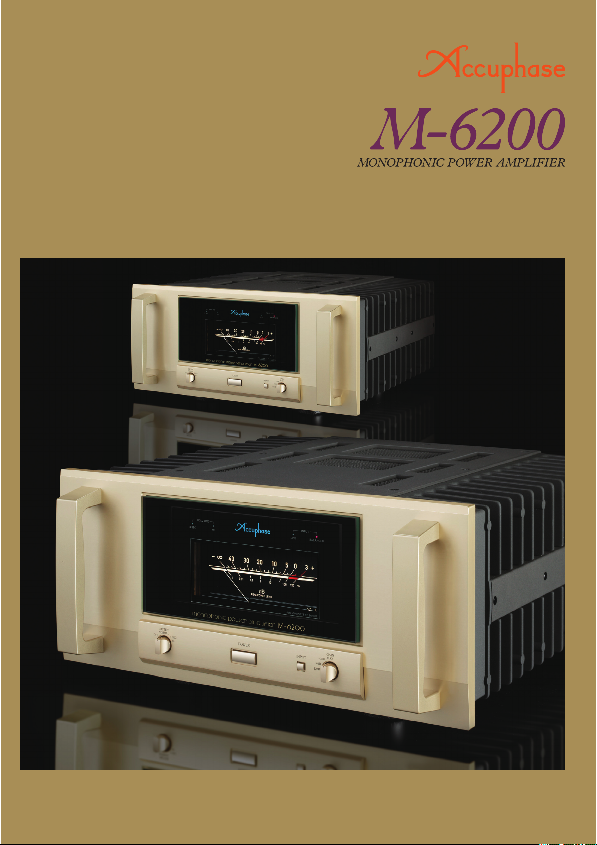
●
Two totally identical power amplifier units driven in parallel
● Output stage
features novel high-power transistor devices in a dual 8-parallel push-pull
arrangement
● Latest low-noise instrumentation amplifier technology
circuit and current feedback topology in amplification stage
use of two M-6200 units with even higher output power
with massi
ve high-efficiency toroidal transformer and large filtering capacitors
● Support for bridged
● Strong power supply
● MCS+
Page 2
Supreme monophonic power amplifier takes the product concept to its ultimate conclusion –
Discrete low-noise instrumentation amplifier construction allows fully balanced signal
transmission, augmented by MCS+ circuit and current feedback topology for outstanding
sound and drastically improved S/N ratio. Hefty power supply and two parallel amplification
units, each featuring an 8-parallel push-pull configuration of new high-power transistors
designed specifically for audio applications, sustain 1200 watts (music signals) into an ultra-low
1-ohm load. Output stage with further lowered impedance realizes a damping factor of 1,000.
Monophonic power amplifiers from Accuphase have
always been at the very forefront of the global high-end
audio scene, as demonstrated by many models that have
made history. While positioned as a successor to the
M-6000, the M-6200 approaches the concept of the power
amplifier from a new vantage point. It achieves an
unprecedented level of performance that again redefines
what a monophonic power amplifier can be.
Retaining the parallel arrangement of two completely identical
amplification circuits, the M-6200 drastically lowers the noise
floor and improves the damping factor. Parallel operation has
the advantage of significantly bolstering output current
capability, as well as enabling extremely low output
impedance. Furthermore, improvements to the NFB circuit
using remote sensing and other technological refinements
result in a damping factor in excess of 1,000 and make the
amplifier capable of delivering constant current down to
extremely low impedance loads. In the input stage, parallel
operation along with optimized gain allocation keeps noise
levels to an absolute minimum, as illustrated by the astonishing S/N ratio of 127 dB at maximum gain and 133 dB at the
-12 dB gain setting. Internally, every aspect of the amplifier
has been reworked, and only the very finest parts and
materials are used. Two identical amplification units are driven
Features and Functions
Two units driven in parallel, each with an 8-parallel push-pull arrangement
■
of high-power transistors deliver linear power progression: 1,200 watts
(music signals) into 1 ohm, 600 watts into 2 ohms, 300 watts into 4 ohms, or
150 watts into 8 ohms.
Strong power supply with massive high-efficiency toroidal transformer in
■
diecast aluminum enclosure and two large 48,000 µF filtering capacitors.
Balanced inputs shut out external noise interference.
■
Low-noise instrumentation amplifier topology in discrete configuration
■
allows balanced signal paths.
Printed circuit boards made from glass cloth fluorocarbon resin with low
■
dielectric constant and minimum loss.
MCS+ (Multiple Circuit Summing) and current feedback principle work
■
together for drastically enhanced S/N ratio.
4-stage gain selector (MAX, -3 dB, -6 dB, -12 dB) also minimizes residual
■
noise.
Phase selector accommodates both pin 2 ⊕ and pin 3 ⊕ type balanced input
■
sources.
in parallel, each featuring an arrangement of newly developed
audio-grade high-power transistors with excellent performance
characteristics. This ensures low impedance of the output and
realizes constant-voltage speaker drive. It is also possible to
use two M-6200 amplifiers in bridged mode for each channel,
thereby creating a system with even more impressive power
output capability, able to deliver 2,400 watts into a 2-ohm load.
Its bold and massive appearance notwithstanding, the M-6200
is a monophonic amplifier that not only impresses through
abundant power and effortlessly dynamic performance but that
reaches to the very heart of the music, expressing even the
most delicate and minute details with stunning realism.
Bridged operation of two M-6200 units allows upgrade to monophonic
■
amplifier capable of delivering 2,400 watts into 2 ohms (music signals).
Large analog peak-reading meter:
■
●
Meter operation and illumination on/off switch
●
Switchable peak hold time: 3 seconds or infinite
Protection circuitry uses non-contact semiconductor (MOS-FET) switches
■
with high voltage rating.
Oversize speaker
■
terminals also accept Y
lugs.
Remote sensing
■
technology using
balanced feedback from
a point near the speaker
terminals results in
lower impedance and
higher damping factor.
+ INPUT
- INPUT
NFB
NETWORK
+
–
–
+
NFB
NETWORK
NFB
NETWORK
Signal Sensing
+
–
Speaker Terminals
GND Sensing
Remote Sensing
+ Signal
- GND
Large high-efficiency
toroidal transformer
Input amplifier/protection circuit assembly
high capacitance
Pre-stage/drive stage power supply assembly
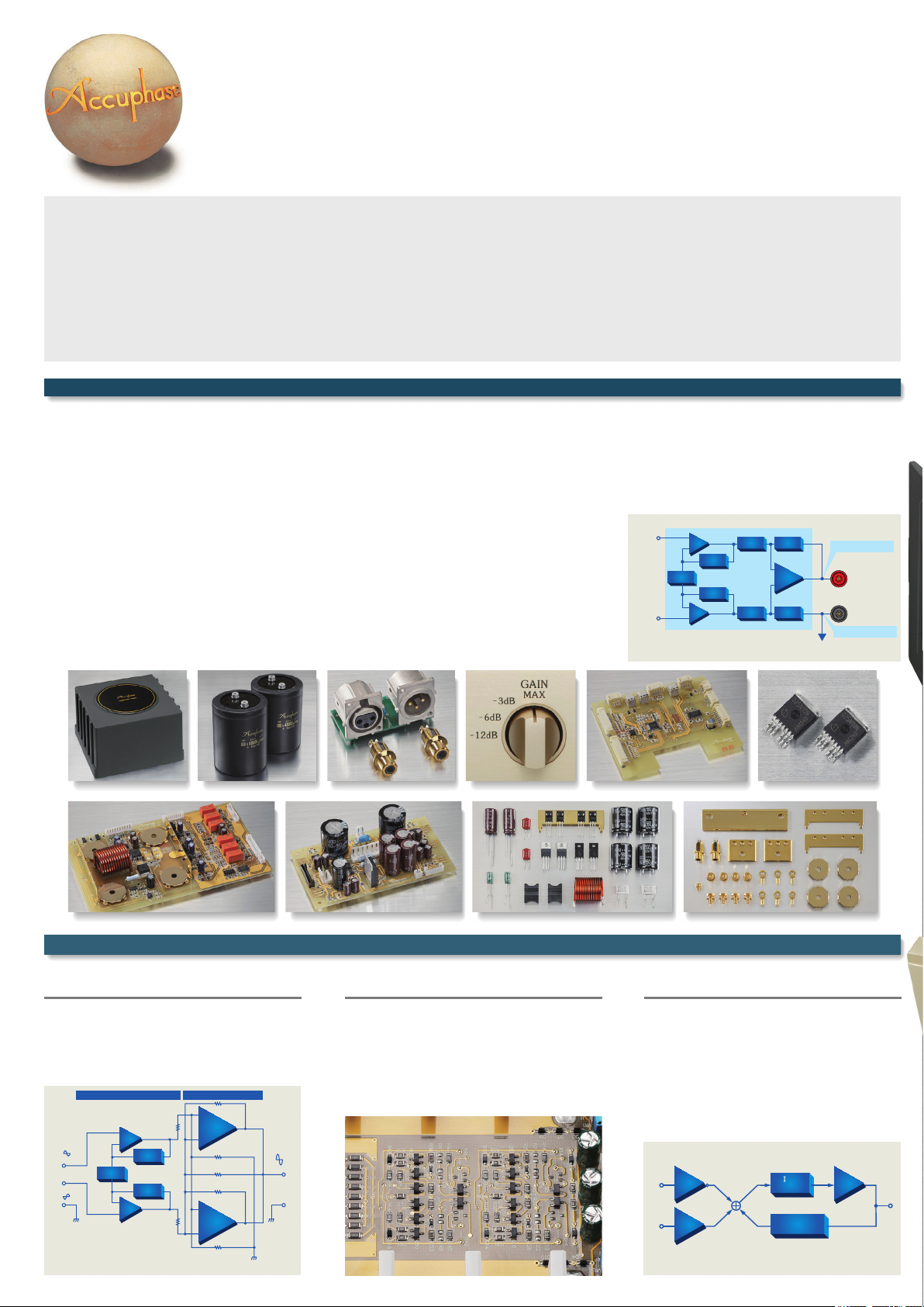
Low-Noise Instrumentation Amplifier Configuration and Further Refined MCS+ Topology
Low-noise instrumentation amplifier in discrete
configuration allows balanced signal paths
The balanced input stage circuitry features instrumentation amplifier topology such as used in high-precision
measuring equipment. This approach ensures perfectly
matched input conditions for the positive and negative
side of the signal and thereby allows the realization of
high-performance balanced signal transmission.
Power Amplifier StageSignal Input Stage
+
8-PARALLEL
POWER
+
–
NFB
GAIN CONTROL
CIRCUIT
NETWORK
NFB
NETWORK
–
+
+
INPUT
INPUT
−
AMPLIFIER
–
+
8-PARALLEL
POWER
AMPLIFIER
‒
OUTPUT
Line/balanced input connectorsFiltering capacitors with
Gain selector
Parts selected for high sound quality and reliability
MCS+ (Multiple Circuit Summing) circuit in
amplifier section drastically improves S/N ratio
The input stage of the amplifier section features
another Accuphase innovation: MCS+ (Multiple
Circuit Summing). This innovative method further
reduces noise and at the same time helps to ensure
rock-stable performance.
Control circuit assembly
Major parts in signal path are gold-plated
MOS-FET switches
Current feedback principle provides excellent
phase characteristics in high frequency range
As shown in the illustration, the M-6200 uses the
output signal current rather than voltage for
feedback. Since the impedance at the current
feedback point is very low, there is almost no phase
shift. A minimal amount of NFB therefore results in
maximum improvement of circuit parameters. The
principle provides excellent stability and is ideally
suited to power amplifiers that handle signals ranging
from extremely low to dynamic, high-volume levels.
TRANS-IMPEDANCE
- INPUT
+ INPUT
BUFFER
BUFFER
AMPLIFIER
- V
CONVERTER
CURRENT ADDER
CURRENT NFB
NETWORK
AMPLIFIER
OUTPUT
Low-Noise Instrumentation Amplifier Configuration
Principle of Current Feedback Amplifier
Page 3

1,300
1,200
1,100
1,000
900
800
755W
755W
700
600
Output power (W)
500
400
300
200
100
Max. output powerMax. output power
Rated output powerRated output power
410W410W
211W
211W
150W150W
8Ω 4Ω 2Ω 1Ω
300W300W
600W
600W
Impedance (Ohms)
High-p ower tr ansisto rs for audio a pplicat ions
1,250W1,250W
1,200W
1,200W
+
–
INPUT
GND
INPUT
Q
1
GAIN SELECTOR
MAX
−
3dB
−
6dB
−
12dB
Q
2
Circuit Diagram of Power Amplification CircuitryOutput Power Characteristics
BIAS
STABILIZER
Q
17
Q
Q
5
Q
3
Q
4
BIAS
STABILIZER
Q
6
Q
7
BIAS
STABILIZER
Q
8
+ B4
Q
9
Q
13
Q
14
Q
10
B4
−
FEEDBACK
NETWORK
DC SERVO
+ B4
Q
11
Q
15
Q
16
Q
12
B4
−
25
Q
26
Q
18
BIAS
STABILIZER
BIAS
STABILIZER
Q
19
Q
27
Q
28
Q
20
BIAS
STABILIZER
+
−
BIAS
STABILIZER
Q
21
Q
29
Q
30
Q
22
BIAS
STABILIZER
BIAS
STABILIZER
Q
23
Q
31
Q
32
Q
24
BIAS
STABILIZER
+ B3
Q
Q
33
41
Q
34
Q
35
Q
36
Q
42
Q
45
Q
49
BIAS
STABILIZER
Q
50
Q
46
B3
−
+ B3
Q
Q
43
37
Q
38
Q
39
Q
40
Q
44
Q
47
Q
51
BIAS
STABILIZER
Q
52
Q
48
B3
−
High-Power TransistorsSignal Input Stage MCS+ (Multiple Circuit Summing)
+ B2
+ B1
Q
Q
Q
Q
Q
Q
Q
53
57
61
65
69
Q
73
77
81
8-PARALLEL PUSH-PULL
Q
Q
Q
Q
Q
Q
Q
58
62
66
54
B2
−
70
Q
74
78
82
B1
−
OUTPUT
+ B2
+ B2
+ B1
Q
Q
Q
Q
Q
Q
Q
55
59
63
67
71
Q
75
79
83
8-PARALLEL PUSH-PULL
Q
Q
Q
Q
Q
Q
Q
56
60
64
68
72
B2
−
Q
76
80
84
B1
−
Power Amplifier Assembly
Output stage with 8-parallel pus h-pull power
arrangement of high-power transistors mounted
directly to large diecast aluminum heat sink,
also c omprising MCS+ c ircuitry and current
feedback amplifier. Tw o complete ly identical
units arranged at left and right are used.
Rear Panel Features
Operation selector allows
bridged operation of two
M-6200 units.
Phase selector accommodates
pin 2 ⊕ and pin 3 ⊕ type
balanced connections.
Page 4

■Using four M-6200 units, upgrading to bridged operation or bi-amping is possible. ■
Bridged operation of two M-6200 units allows upgrading
Right speakerLeft speaker
to a monophonic amplifier with even higher power.
*
For connecting the SPEAKER terminals to each other, use
speaker cable of the same grade as for other speaker connections.
*
Operation selector of left channel/right channel q unit: NORMAL
*
Operation selector of left channel/right channel w unit: REVERSE
−
−
+
−
+
−
Connect the input signal either to the balanced or the unbalanced inputs onall units.
Example for bi-amping connectionExample for bridged connection
LOW
+−
Right speakerLeft speaker
HIGH
LOW
In a bi-amped setup, the speaker units for the LOW
frequency range and HIGH frequency range are driven by
separate amplifiers, for optimum sound quality.
*
The speakers must have a built-in crossover network and
separate inputs for LOW and HIGH range.
*
Set the operation selectors of all four units to NORMAL.
Branch outputBranch output
+−
HIGH
BALANCED
LINE
L L
RR
LINE
BALANCED
q
Hold time indicator
3 SEC /
∞
Left-channel unit q Left-channel unit w
Preamplifier
+−
Right-channel unit q Right-channel unit w
wPower meter
(dB and % indication)
eInput indicator
LINE / BALANCED
BALANCED
LINE
L L
+−
BALANCED
Left-channel unit q Left-channel unit w
Branch outputBranch output
Preamplifier
+− +−
RR
LINE
Right-channel unit q Right-channel unit w
Rear panelFront panel
i Inputs
LINE / BALANCED
(One is used for signal pass-through)
o Speaker terminals
(Same output from both sets)
r
Meter illumination/operation/
hold time selector
OFF / NORMAL / 3 SEC /
∞
tPower switch
yInput selector button
LINE / BALANCED
M-6200 Guaranteed Specifications
● Continuous Average Output Power (20 - 20,000 Hz)
1,200 watts into 1 ohm
(1-ohm loads allowed with music signals only)
600 watts into 2 ohms
300 watts into 4 ohms
150 watts into 8 ohms
Bridged mode (2 units) 2,400 watts into 2 ohms
(2-ohm loads allowed with music signals only)
1,200 watts into 4 ohms
600 watts into 8 ohms
● Total Harmonic Distortion
0.05% with a 2-ohm load
0.03% with a 4 to 16-ohm load
● Intermodulation Distortion
0.01%
● Frequency Response
At rated continuous average output: 20 – 20,000 Hz +0 -0.2 dB
At 1 watt output: 0.5 – 160,000 Hz +0 -3.0 dB
● Gain 28.0 dB (GAIN selector in MAX position)
● Gain Selection -12 dB, -6 dB, -3 dB, MAX
Output Load Impedance
●
With music signals: 1 to 16 ohms
Remarks
★
This produc t is available in versions for 120/220/23 0 V AC. Make sure that the voltage shown on th e rear panel matches the AC line voltage in your area.
★
230 V version has an Eco Mode that swi tches power of f after 120 minutes of inactivit y.
★
The shape of the AC inlet and plug of the supplied power cord depends on the voltage rating and destination country.
Supplied accessory
●
A
C power cord
Continuous output: 2 to 16 ohms
uGain selector
-12dB / -6dB / -3dB / MAX
!0Operation selector
NORMAL / REVERSE
[Guaranteed specifications are measured according to EIA standard RS-490.]
!1Balanced input
phase selector
● Damping Factor 1,000
● Input Sensitivity (with 8-ohm load)
1.38 V for rated continuous average output
0.11 V for 1 watt output
● Input Impedance Balanced: 40 kilohms
Line: 20 kilohms
● Signal-to-Noise Ratio
(A-weighted, with input shorted)
127 dB (GAIN selector in MAX position)
133 dB (GAIN selector in -12 dB position)
At rated continuous average output
● Output Level Meter -40 dB to +3 dB (dB / % indication)
Logarithmic compression scale
Display illumination off switch
Peak hold time select: 3 seconds,
● Power Requirements 120/220/230 V AC, 50/60 Hz
● Power Consumption 100 watts idle
575 watts in accordance with IEC 60065
● Maximum Dimensions Width: 465 mm (183.1")
Height: 220 mm (86.6")
Depth: 499 mm (196.5")
● Mass 40.2 kg (88.6 lbs) net
50.0 kg (110.2 lbs) in shipping carton
!2AC power connector
∞
★
●
The specifications and appearance of this product are subject to change without notice.
5年間保証
D1505Y PRINTED IN JAPAN 850-2191-00(B1)
 Loading...