


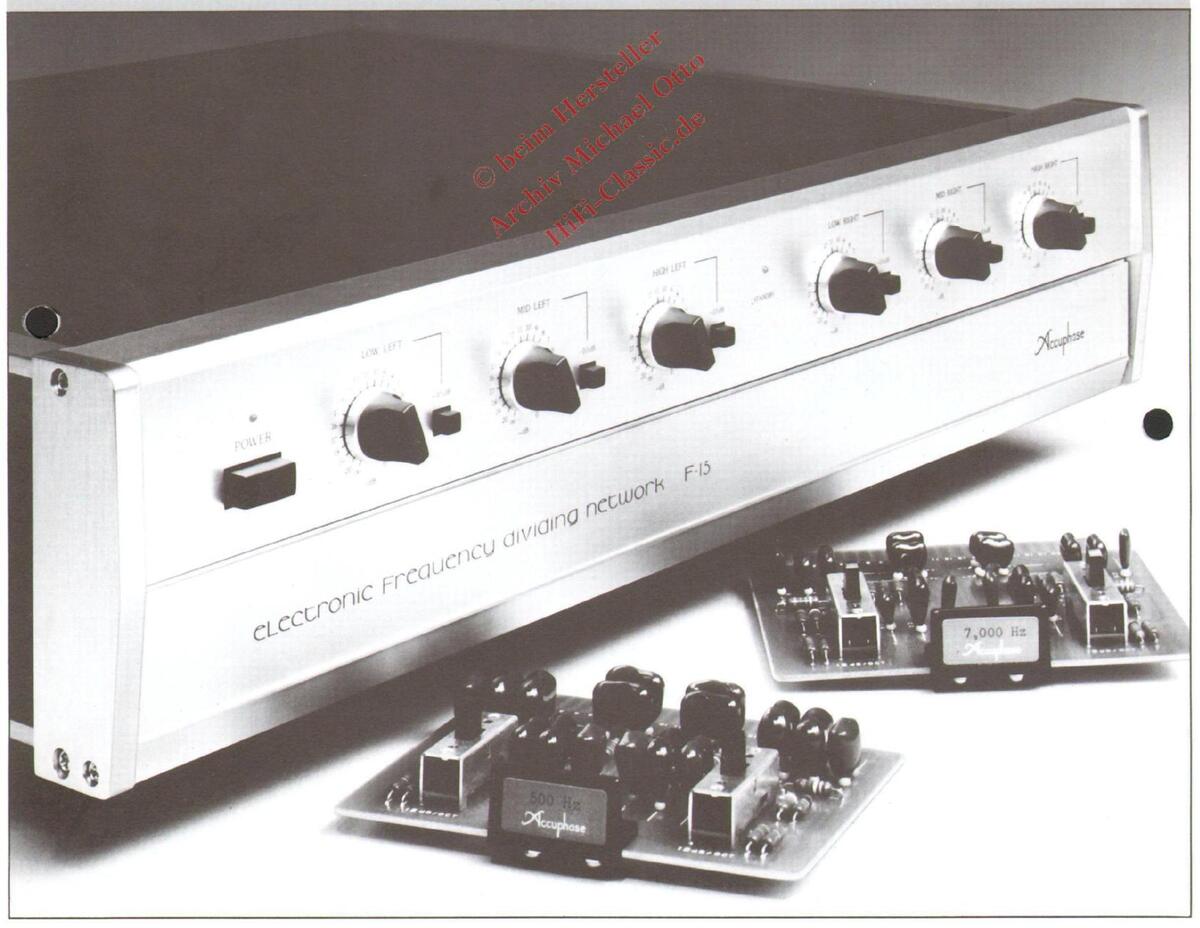
electronic Frequency dividing network
Direct coupling unit amplifiers formed with push-pull driven circuitries in all stages Precision level control by 0.5dB step attenuator Subwoofer output provided for richer bass reproduction
ELECTRONIC FREQUENCY DIVIDING NETWORK
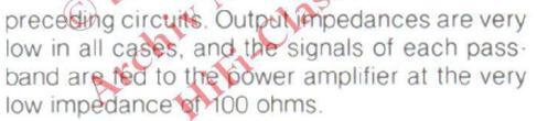
addition of Servo Amps IC1 and IC2, whose time constant is determined by C1~C4 and R1~R4.
Because the time constant of the Servo Amplifiers, if set at one point, would become too large due to the gain of the unit amp being "1", certain technical measures had to be taken to prevent a flattening of attenuation slope characteristics at the low frequency range, and a resulting distortion. They included connecting the Miller Integration circuits of IC1 C3 R3 and IC2 C4 R4 in series. Also included was the setting up of time constants for a total of three stages with the addition of C1 R1 and C2 R2 to reduce the CR value of one stage. These measures account for the excellent low distortion characteristics of the F-15 in the low tecouency range.
In addition, all unit amplifiers in the F-15 operate as pure DC amplifiers. Not a single coupling capacitor is used anywhere, which fact underlines the seriousness with which sound quality was given top priority in designing the F-15 Electronic Frequency Dividing Network.
3 0.5 dB STEP PRECISION LEVEL CONTROL
Left and right channel, independent LOW, MID and HIGH level attenuator knob controls are concentrated on the front panel. They permit precise level control of each audio passband conveniently, without depending on the volume control of the power amplifiers. These attenuator knobs provide 1dB step attenuation.
A further 0.5 dB step attenuation control is possible by using them in combination with the 0.5 dB Shift Buttons (see Fig. 1). This provides 41-point attenuation in the control range from 0 to 20.5 dB and infinity.
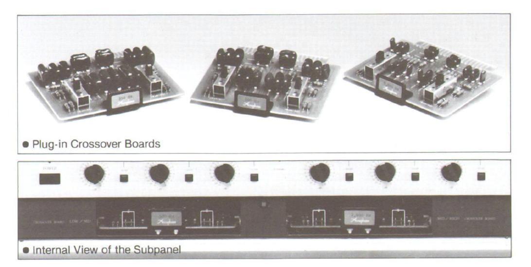
CROSSOVER FREQUENCIES SELECTABLE WITH PLUG-IN CROSSOVER FREQUENCY BOARDS
ed by interchanging the plug-in type Crossover Frequency Boards. They are designated as CROSSOVER BOARD in Figure 1. Each block contains CR elements that are neatly laid out for both the left and right channels.
Since these CR elements greatly influence sound quality, only carefully selected, precision metal film resistors and high quality silveredmica capacitors were used to prevent sound deterioration.
The crossover frequencies can be changed simply by opening the frontside subpanel cover and inserting the desired plug-in type Crossover Frequency Boards in their prescribed sockets. These boards are sold separately. All standard crossover frequencies are available, and their respective Crossover Board Part Numbers are listed in a separate table.

frequency between the most common 12dB/ oct., or 18dB/oct., which is suitable for certain
horn type speakers can be made easily with the Selector Switch that is positioned on the Crossover Board.
PERFECT MUTING ACTION PROTECTS SPEAKERS
The F-15 has a built in positive-action muting circuit that cuts of the output if the Crossover Frequency Board is pulled out during amplifier operation this is a protection circuit that prevent possible damage to the speaker from the shockhoise that would otherwise occur.
TWO-WAY, FOUR-WAY, FIVE-WAY SYSTEMS ALSO POSSIBLE
Way system, it can also be used readily for a Two-Way (Bi-Amplification) system by using the CB-2 Way Board that is sold separately and plugging it into the Mid-High Frequency Crossover Socket.
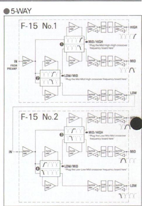
Two F-15 units can also be used simultaneously to form a 4- or 5-Way multi-amplification system.
MODEL No. OF THE CROSSOVER BOARDS
| Crossover Frequency | Model No. |
|---|---|
| 70Hz | CB-70 |
| I 00Hz | CB-100 |
| I 30Hz | CB-130 |
| 180Hz | CB-180 |
| 250Hz | CB-250 |
| 290Hz | CB-290 |
| 300Hz | CB-300 |
| 350Hz | CB-350 |
| 500Hz | CB-500 |
| 650Hz | CB-650 |
| 800Hz | CB-800 |
| I,000Hz | CB-1000 |
| I,200Hz | CB-1200 |
| I,800Hz | CB-1800 |
| 2,500Hz | CB-2500 |
| 3,500Hz | CB-3500 |
| 5,000Hz | CB-5000 |
| 7,000Hz | CB-7000 |
| 8,000Hz | CB-8000 |
| 10,000Hz | CB-10000 |
| 12,500Hz | CB-12500 |
| 2-WAY BOARD | CB- 2 Way |
UARANTY SPECIFICATIONS
PERFORMANCE GUARANTY: All Accuphase product specifications are guaranteed as stated.
GAIN: -0.5dB
MAXIMUM OUTPUT: 10 Volts (from 20Hz to 20,000Hz with no more than 0.01% total harmonic distortion)
TOTAL HARMONIC DISTORTION: (New IHF Standard)
0.003% (from 20Hz to 20,000Hz at 2 Volts output)
20Hz to 20,000 Hz; + 0, -0.2dB 0.17Hz to 1,000,000 Hz; + 0, -3.0dB (equivalent bandwidth)
CROSSOVER FREQUENCY: Selectable by Plug-in Modules
CROSSOVER CHARACTERISTICS: -3.0dB, ±5% FILTER SLOPE:
-12dB/oct., -18dB/oct. changeable INPUT IMPEDANCE: 50k ohms
OUTPUT IMPEDANCE: 50K Offins OUTPUT IMPEDANCE: LOW; 100 ohms MID; 100 ohms HIGH: 100 ohms SUBWOOFER; 1k ohms
LOAD IMPEDANCE: LOW, MID, HIGH; 1k-ohm minimum SUBWOOFER; 10k-ohm minimum
A-WEIGHTED SIGNAL-TO-NOISE RATIO: 100 dB at 0.5V output
LEVEL ADJUSTMENT: 0.5dB stepping type controls from 0dB to -20.5dB for respective audio passbands
POWER REQUIREMENT: Voltage Selector for 100, 117, 220 and 240 Volts; 50/60 Hz operation CONSUMPTION; 25 Watts
SEMICONDUCTOR COMPLEMENT: 98 Tr's 46 EETs 12 IC s and 58 Di's
DIMENSIONS: 445 mm (17-1/2 inches) width, 109 mm (4-5/16 inches) max. height, 273 mm (1411116 inches) datth
WEIGHT: 8.3kg (18.3 lbs) net, 12.7kg (28.0 lbs) in shipping carton
An audio system which uses electronic circuits to create crossover frequencies and form separate audio passbands, which are then amplified and reproduced by their own exclusive amplifiers and speakers, is called a "Multi-Amplification System". It becomes a large scale system for stereo reproduction since one amplifier is required for each divided passband, both for the left and right channels.
However, the system eliminates the shortcomings of conventional LC crossover networks by ensuring maximum 100% speaker performance. This and other advantages are gaining increasing recognition, and the system is now being widely used in higher grade audio systems to obtain further improvement in audio sound reproduction.
The difference in the sound quality capability of a multi-amplification system becomes increasingly clear when higher quality program sources are used. Improvements beyond imagination in the depth, presence, transparency and reverberation sound characteristics are now possible from highest quality program sources with multichannel amplification.
The electronic frequency dividing network which creates the audio passbands forms the "heart" of a multi-amplification system. It is, therefore, no exaggeration to say that its quality largely determines the quality of the overall multiamp stereo system.
All the unit amplifiers used in the Accuphase F-15 Electronic Frequency Dividing Network employ the basic complementary-symmetry push-pull circuit in every stage with FET (Field-Effect Transistor) inputs and wideband transistor outputs. Together with the most carefully selected CR elements, these circuits ensure excellent, accurate crossover frequency characteristics.
The crossover frequencies can be changed readily by using different plug-in type Crossover Frequency Boards. These boards which are available for various frequencies can be used in both the Accuphase F-15 and F-5 Frequency Dividing Networks.
The F-15 also provides 0.5dB step precision level control, as well as an Output Jack and switching circuit to make up a Subwoofer System.
The sound quality of speaker systems has been improving steadily in recent years, and also noticeable is the growing tendency toward bigger and more powerful speakers. In this respect, we firmly believe that the F-15 can play a vital role in setting up a very effective multiamplification system in which these recently improved, large size horn type speakers are fully utilized.
LOW NOISE, WIDEBAND UNIT AMPS FEATURE FET INPUTS AND COMPLEMENTARY PUSH-PULL OUTPUTS
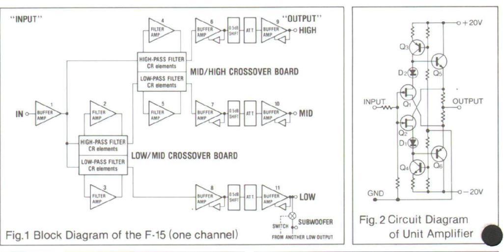
An electronic frequency dividing network is made up of a combination of active filter amps and buffer amplifiers. Figure 1 shows the block diagram of the F-15. All unit amps are identical at Gain "1". Amplifiers (2) to (5) are Active Filter Amps which form the crossover frequency characteristics in combination with their associated CR elements.
Amplifier (1) and those from (6) to (11) are buffer amplifiers which serve to minimize the effects of their respective following circuits on
The sound quality performance of an electronic frequency dividing network depends on the quality of its unit amplifiers and CR elements which, together, determine its filter characteristics. The sound improvement potential of a multi-amplification system cannot be realized without the closest attention to quality of those devices.
Therefore, in developing the F-15, various unit amplifier circuits were thoroughly examined and tested before the push-pull circuit of Figure 2, with its simple, straightforward signal path and exceptional performance characteristics was finally adopted. The input stage comprises a complementary push-pull source-follower configuration that utilizes low noise, high gm (mutual conductance) FETs. The output stage utilizes wideband transistors in a complementary, symmetry push-pull circuit.
All the active devices used were most discriminately selected and local feedback was employed instead of loop feedback to obtain the utmost limits of performance. Q3 and Q4 function to supply the constant, regulated current necessary to prevent distortion from large amplitude signals. In addition, low distortion over a wide passband is achieved by connecting the drains of Q1 and Q2 to the emitter of Q6 and Q5 to prevent Miller Effects.
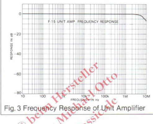
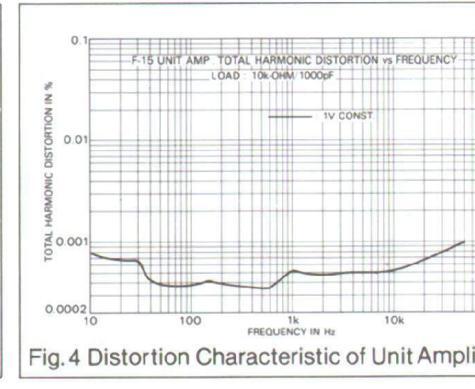
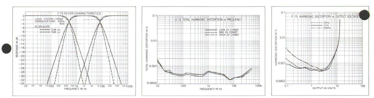
Figure 3 shows the frequency response characteristics of the F-15's unit amplifiers and their wide range which extends to 7 MHz (at -3 dB). Another outstanding feature of these unit amplifiers is their low distortion which has been held to less than the measurable limit of 0.001 % as shown in Figure 4.
2 DC SERVO CONTROL PERMITS PURE DC OPERATION OF OUTPUT UNITAMPS
Even without taking special measures, there was very little likelihood of DC drift in the F-15's unit amplifiers because of their high stability and Gain "1" function. However, Servo Control was added to make absolucertain that there would be no DC drift which is imperative for high quality sound.
For example, even the slightest DC drift in a stage before the attenuator can cause noise during attenuator adjustment. Also even a very slight DC drift at the output of a frequency divider can cause poor sound due to undesirable DC drift in the output of the power amplifier.
DC Servo Control employed for unit amplifiers Nos. 6~11 eliminates all such DC drift possibilities. Figure 5 shows the circuit used. It is based on the circuit of Figure 2, with the

2-WAY (Bi-Amplification)
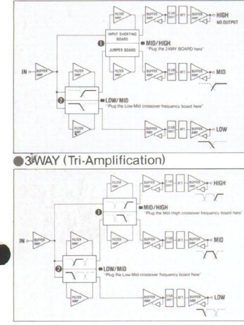
frequency, requires one crossover frequency MID" crossover socket. The special 2-WAY
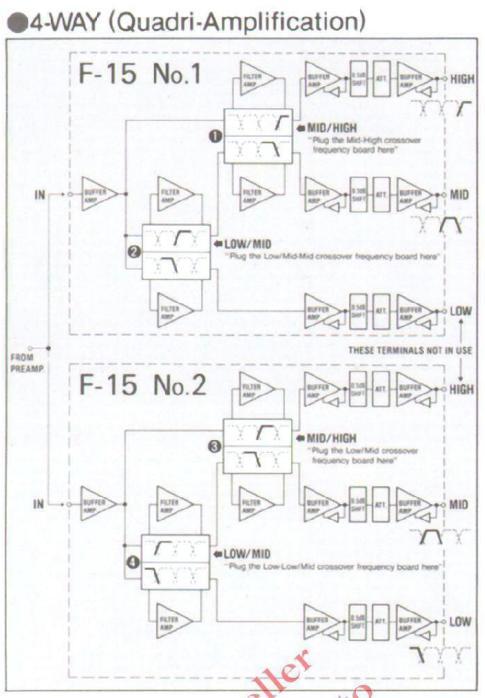
Two F-15 units are required for a Quadri Amplification installation. Both units should be connected in parallel, and led simultaneously with the preamplifier output. Two crossover boards of identical pequency should be used for the crossover boards designated (2) and (3) This means an additional cost, but sound quality that can be obtained through this amplification is well worth it. The LOW OUTPUT of the F-15 No. 1 and the HIGH OUTPUT of the F-15 No. 2
ccuphase
ELECTRONIC EBEQUENCY DIVIDING NETWORK
In a 5-WAY Amplification system, two F-15 S/N ratio, preamplifier output should be connected to the INPUT of F-15 No. 1, which provides the mid-high and high audio frequency No. 1 is fed into the F-15 No. 2, which then supplies the middle, mid-low and low audio


 Loading...