

Page 1
● Revolutionary AAVA volume control ● Power MOS-FETs in triple
parallel push-pull configuration driven in pure class A ● Current feedback
principle and MCS+ topology in power amplifier section ● Logic-control
relays for straight and short signal paths ● Sturdy power supply with
large toroidal transformer and high filtering capacity ● EXT PRE button
allows independent use of preamplifier and power amplifier sections
Page 2
The ultimate integrated pure class A amplifier – Power MOS-FETs arranged
in triple parallel push-pull configuration. Innovative AAVA volume control.
Strong power supply with large toroidal transformer and high filtering capacity
supports linear output progression of 120 watts/ch into 2 ohms, 60 watts/ch
into 4 ohms, or 30 watts/ch into 8 ohms. Power amp section uses current feedback
for optimum high-frequency phase characteristics and MCS+ topology.
The first integrated pure class A amplifier from
Accuphase, the E-530, drew a lot of attention and
praise. The E-550 now takes over as a further
improved and fully redesigned successor model.
It stands at the pinnacle of integrated amplifiers,
featuring latest technology and strictly selected
high-quality parts. For the first time in an integrated
amplifier, it offers the revolutionary AAVA type
volume control. In AAVA, amplification and volume
control are fully unified, and no variable resistors
are used. This ensures excellent sound quality and
performance, but the circuitry requires a
considerable amount of space. In order to enable
the use of AAVA in an integrated amplifier,
advanced design know-how and mounting
technology were brought into play, to increase
component density while keeping sonic purity and
performance at the high level that is the hallmark
of Accuphase. The result speaks for itself.
The power amplifier section features the highly
acclaimed current feedback principle developed
by Accuphase, as well as further improved “MCS+”
circuit topology, for even better electrical
characteristics. The output stage devices are
AAVA (Accuphase Analog Vari-gain Amplifier) volume control
■■
■ Volume control resolution
■■
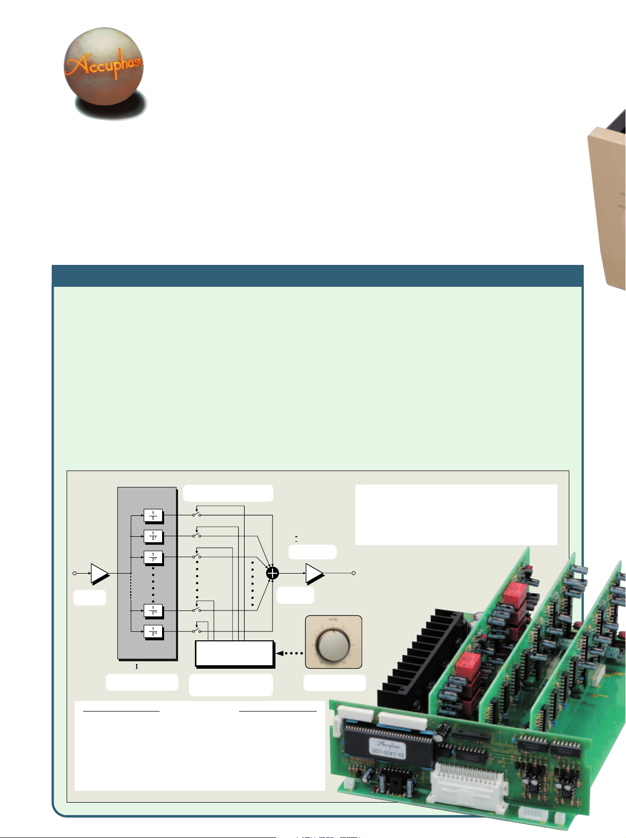
AAVA adjusts the listening volume by means of 16 current switches which are
operated by 16 weighted V-I converter amplifiers. The number of possible volume
steps set by the combination of these converter amplifiers is 2 to the power of
16 = 65,536.
■■
■ AAVA maintains high S/N ratio and uniform frequency response
■■
With conventional volume controls, the impedance increases significantly at
settings that correspond to normal listening levels, thereby leading to increased
noise. Because AAVA performs adjustment by selective use of V-I converter
amplifiers (changing the actual gain), there is no change in impedance and
thus no deterioration of S/N ratio or alteration of frequency response. Changing
the volume with AAVA does not mean introducing noise or detracting from the
high performance of the amplifier.
■■
■ Same operation feel as a conventional high-quality volume control
■■
The volume control knob position is detected by a dedicated CPU which in
turn selects the current switches for AAVA operation. Operating the knob
therefore feels exactly the same as with a conventional control, and as before,
operation via the remote commander is also possible.
power MOS-FETs famous for their musical
qualities, arranged in a triple parallel push-pull
configuration and driven in pure class A. Low
output impedance and constant voltage drive
ensure superb speaker control. The large highefficiency toroidal transformer (430 VA) in the
power supply, along with eight 10,000 µF filtering
capacitors selected for their sonic properties
support linear progression of output regardless of
impedance, with a per-channel rating of 120 watts
into 2 ohms, 60 watts into 4 ohms, or 30 watts into
8 ohms.
■■
■ Simple circuit configuration
■■
AAVA unifies the amplifier and volume control functions, resulting in a circuit
that is electrically very simple. Long-term reliability is excellent, with performance
and sound quality that will remain unchanged also after prolonged use.
■■
■ AAVA means analog processing
■■
The AAVA circuit converts the music signal from a voltage into a current,
switches gain by means of current switches, and then reconverts the current
into a voltage. The entire process is carried out in the analog domain.
■■
■ No more left/right tracking differences or crosstalk
■■
Because AAVA is an electronic circuit employing highly precise metal film
resistors, there is virtually no left/right tracking error also at low volume levels.
Since channels can be kept separate, crosstalk also does not present a problem.
■■
■ Attenuator and balance control also implemented by AAVA
■■
The functions of the attenuator and the left/right balance control are covered
by the AAVA circuit as well, eliminating the need for additional circuit stages.
Keeping the configuration simple helps to maintain high performance and sonic
purity.
16 current switches
(65,536 possible combinations)
BUFFER
INPUT
Input music
signal
V- I Converter
Conversion into current with 16
weighting stages (1/2 - 1/216)
Volume
Balance
CPU
Attenuator
CPU detects position of volume
knob and operates current on/off
switches according to knob position
Current values
are added
AAVA operation
AAVA operates by feeding the music signal to a V-I (voltage - current) converting amplifier
where it is weighted in 16 steps [1/2, 1/22, ... 1/215, 1/216]. The 16 current steps are turned
on or off by 16 current switches, and the combination of switch settings determines the
overall volume. The switching operation is controlled by a CPU according to the position of
the volume control knob. The combined signal current forms a variable gain circuit that
adjusts the volume. Finally, the combined current is converted back into a voltage by an
I-V (current - voltage) converter.
I-V Converter
Reconversion of
current into voltage
Volume knob is turned
and position is detected
The newly developed volume control called AAVA (Accuphase Analog
Vari-gain Amplifier) is totally different from conventional controls using
resistors. Because the music signal does not pass through variable
resistors, it is not affected by changes in impedance. This means that
high signal-to-noise ratio and low distortion of the signal are maintained.
Adjusting the volume does not introduce any deterioration in sound quality.
■■
■ AAVA control assembly with
■■
OUTPUT
three AAVA units and CPU
arranged neatly on a motherboard
■■
■ Output
■■
amplifie
triple p
power M
mounte
sink
Page 3

■■
■ Output stage and power
■■
amplifier assembly with
triple parallel push-pull
power MOS-FET devices
mounted to large heat
sink
+
B
3
INPUT
- B
3
BIAS
STABILIZER
Q
1
Q
5
Q
7
Q
3
BIAS
STABILIZER
Bias
stabilizer
Q
2
Q
6
Q
8
Q
4
BIAS
STABILIZER
MCS
+ (
Multiple Circuit Summing-up)
Q
9
Q11Q
Q10Q
Q12Q
■ Supplied remote commander RC-200
Allows volume adjustment and input
source switching
■ The output stage uses power
MOS-FETs in a triple parallel
push-pull configuration driven
in pure class A. Output power
progression is linear, with a
per-channel rating of 120 watts
into 2 ohms, 60 watts into 4
ohms, or 30 watts into 8 ohms.
■ Power amplifier section uses MCS+ topology and current feedback principle to achieve
excellent sound quality and optimum high-frequency phase characteristics.
■ Logic-controlled relays assure high
sound quality and long-term
reliability.
■ Balanced input connectors shut out
external noise interference.
■ “High Carbon” cast iron insulator feet
with superior damping characteristics further enhance sound
quality.
■ Ample power supply with
large high-efficiency
toroidal transformer (430
VA) and 10,000 µF × 8
filtering capacitors
2
■ Analog peak power
meters
■ Option board slots allow
functional expansion.
■ Two sets of large-size speaker terminals accept either Y lugs or banana plugs.
■ E-550 front panel switching
enables MC/MM selection
for Analog Disc Input Board
AD-20.
■ EXT PRE button and
preamplifier output/power
amplifier input connectors
allow independent use of
preamplifier and power
amplifier sections.
Q
17
BIAS
STABILIZER
Q
18
REGULATOR
NFB
NETWORK
REGULATOR
Q
13
15
14
16
+
B
1
+
Q
Q
19
Q
20
Q
21
23
Q
Q
22
24
-
B
1
B
Q
25
OUTPUT
Q
26
-
B
2
Gold-plated input/output jacks connected directly to relays
Toroidal transformer Filtering capacitors
Power MOS-FET devices
Large-size speaker terminals
Page 4

■ Tone controls using summing active filters for
optimum sound quality
Three types of option boards can be used in the E-550: the
Option Boards
Digital Input Board DAC-20, Analog Disc Input Board
-
Input Output
■ Loudness compensator for enhanced bass at low
listening levels
Compensator characteristics
■
Front panel
■
Rear panel
Option board
installation slots
A1
F1
VR1
F2
VR2
Tone control circuit principle
18
16
14
12
10
8
6
4
2
0
Response in dB
-2
-4
-6
10 100 1k 10k 100k
LOUDNESS COMPENSATOR: ON
Frequency in Hz
-
A2
AD-20, and Line Input Board LINE-10. These boards can be
installed in the rear-panel slots as required.
● It is possible to install two identical boards.
● The Digital Input Board DAC-10, Analog Disc Input Board AD-9/
AD-10, and Line Input Board LINE-9 can also be used.
● When using the AD-9/AD-10, the MC/MM button of the
E-550 has no effect. MC/MM switching must be performed on the
board.
★
A Input selector
LINE 2 LINE 1 LINE-BAL CD-BAL CD
TUNER OPTION 1 OPTION 2
B Left/right channel output meters
C Function indicator LEDs
D Volume control
E Power switch
F Speaker selector OFF A B A+B
G Copy selector 1➞2 OFF 2➞1
H Recording output selector REC OFF, SOURCE, 1, 2
I Function buttons
MC/MM, EXT PRE, MONO/STEREO, Meter ON/OFF
Compensator, Tone control ON/OFF
Remarks
★
This product is available in versions for 120/230 V AC. Make sure that the voltage shown on the
rear panel matches the AC line voltage in your area.
★
The shape of the AC inlet and plug of the supplied power cord depends on the voltage rating and
destination country.
J Bass control
K Treble control
L Balance control
M Attenuator button
N Headphone jack
O Line inputs (unbalanced)
P Tape recorder inputs and outputs
Q Left/right speaker output terminals A/B
R CD/LINE inputs (balanced)
S Preamplifier outputs
21
T Power amplifier inputs
U AC inlet
21
★
■ Supplied accessories: • AC power cord
• Remote Commander RC-200
Pressing this
button opens
the sub panel.
Digital Input Board DAC-20
The board features an MDS (Multiple Delta Sigma) ++ type
D/A converter and allows direct digital connection of a CD
player, MD or DAT recorder or other component with digital
output (sampling frequency up to 96 kHz, 24-bit), for highquality music reproduction.
● Inputs for coaxial and optical fiber connections are
provided.
Analog Disc Input Board AD-20
This board serves for playback of analog records. It
contains a high-performance, high-gain phono equalizer.
● MC/MM switching is possible on the front panel of the E-550.
● Internal DIP switches control MC input impedance and
subsonic filter on/off.
Gain: 62 dB
MC
Input impedance: 10/30/100 ohms
Gain: 36 dB
MM
Input impedance: 47 kilohms
(selectable)
Line Input Board LINE-10
AD-20
Option board installation example
This option board provides an additional set of unbalanced
line inputs.
GUARANTEED SPECIFICATIONS
[Guaranteed specifications are measured according to EIA standard RS-490.]
● Continuous Average Output Power (both channels driven, 20 ~ 20,000 Hz)
Note: Ratings marked ✽ are for music signals only.
● Total Harmonic Distortion (both channels driven, 20~20,000 Hz)
● Intermodulation Distortion 0.01%
● Frequency Response HIGH LEVEL INPUT/POWER INPUT
For rated continuous average output:
For 1 watt output:
● Damping Factor 140 (with 8-ohm load, 50 Hz)
● Input Sensitivity, Input Impedance
Input
HIGH LEVEL INPUT
BALANCED INPUT 77.7 mV 14.2 mV 40 kΩ
POWER INPUT 0.617 V 113 mV 20 kΩ
● Output Voltage, Output Impedance PRE OUTPUT: 0.617 V, 50 ohms
● Gain HIGH LEVEL INPUT ➞ PRE OUTPUT: 18 dB
● Tone Controls Turnover frequency and adjustment range
● Loudness Compensation +6 dB (100 Hz)
● Attenuator –20 dB
● Signal-to-Noise Ratio
Input
HIGH LEVEL INPUT 98 dB 103 dB
BALANCED INPUT 92 dB 103 dB
POWER INPUT 120 dB 117 dB
● Power Level Meters Logarithmic compression, peak reading meters
● Load Impedance 2 ~ 16 ohms
● Stereo Headphones Suitable impedance: 8 ~ 100 ohms
● Power Requirements
● Power Consumption 200 watts idle, 300 watts in accordance with IEC-60065
● Maximum Dimensions Width 465 mm (18-5/16”)
● Mass 23.9 kg (52.7 lbs) net
● Supplied Remote Commander RC-200
Remote control principle: Infrared pulse
Power supply: 3 V DC (IEC R03 batteries x 2)
Maximum dimensions: 56 mm × 75 mm × 26 mm
Mass: 153 g (including batteries)
150 watts per channel into 1 ohm (✽)
120 watts per channel into 2 ohms
60 watts per channel into 4 ohms
40 watts per channel into 6 ohms
30 watts per channel into 8 ohms
0.05% with 2-ohm load
0.02% with 4 to 16-ohm load
20 ~ 20,000 Hz +0, –0.2 dB
2 ~ 150,000 Hz +0, –3.0 dB
For rated output For 1 W output (EIA)
Sensitivity
77.7 mV 14.2 mV 20 kΩ
(at rated continuous average output)
POWER INPUT ➞ OUTPUT: 28 dB
BASS: 300 Hz ±10 dB (50 Hz)
TREBLE: 3 kHz ±10 dB (20 kHz)
Input shorted (A weighting)
S/N ratio at rated output
EIA S/N
Output dB/% scale
AC 120 V/230 V (Voltage as indicated on rear panel) 50/60 Hz
Height 196 mm (7-11/16”)
Depth 427 mm (16-13/16”)
30.0 kg (66.1 lbs) in shipping carton
Input
impedance
• Specifications and design subject to change without notice for improvements.
http://www.accuphase.com/
K0505Y PRINTED IN JAPAN 851-0152-00 (AD1)
 Loading...