

Page 1
m Revolutionary AAVA-II volume control m Parallel push-pull
output stage with high-power transistors delivers plenty of quality
power m Instrumentation amplifier principle enhances current
feedback and MCS+ topology in power amplifi er section m Logic-
control relays for straight and short signal paths m Robust power
supply with large toroidal transformer and high filtering capacity
Page 2

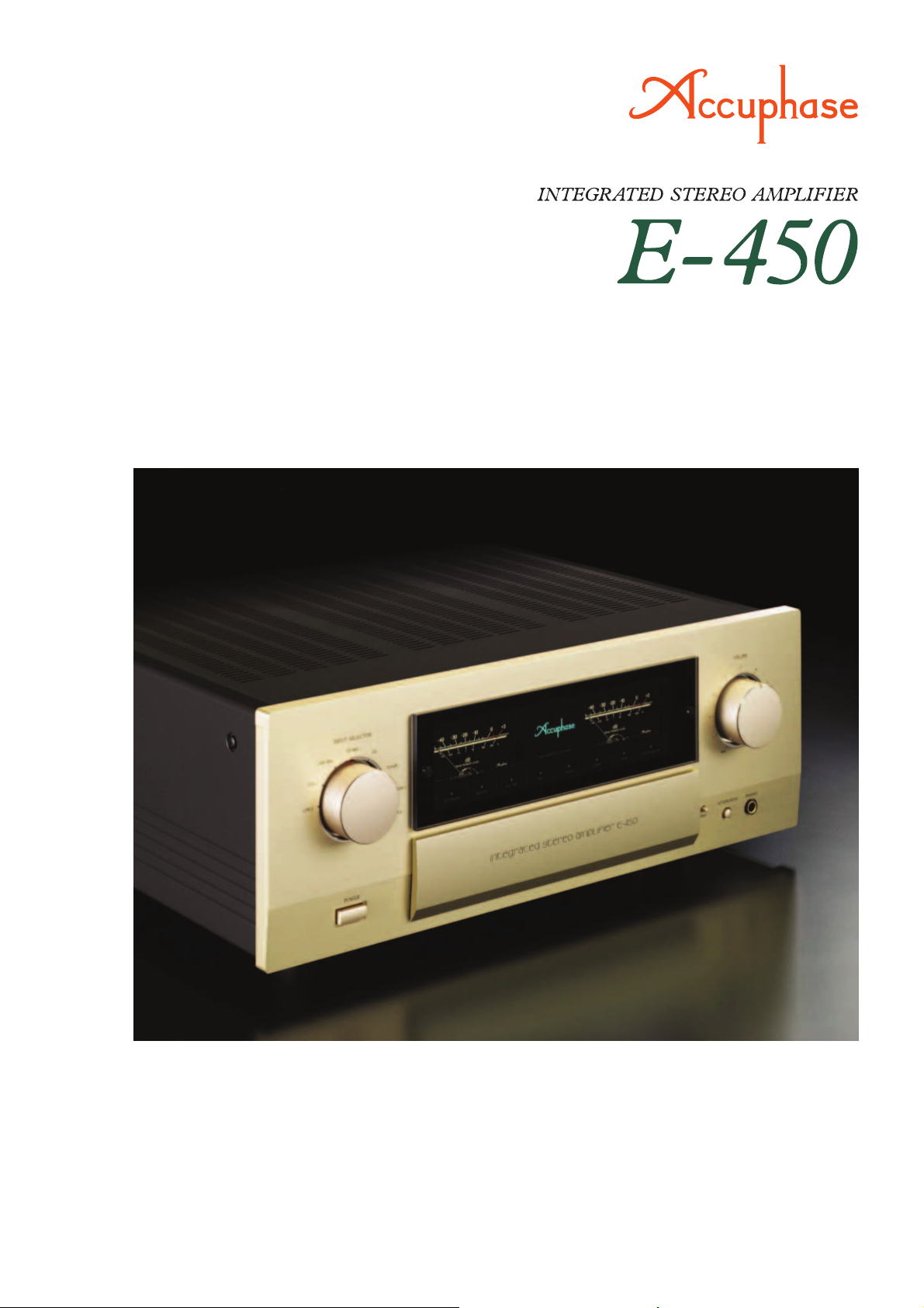
High-class integrated amplifi er with 180 watts per channel (8 ohms) – Innovative AAVA-II volume control opens up new musical frontiers. High-power
transistors operate in a parallel push-pull arrangement. Power supply with
large, highly effi cient toroidal transformer and oversized fi ltering capacitors
sustains ample power. Instrumentation amplifi er confi guration in power amplifi er makes optimum use of current feedback design combined with further improved MCS+ topology, resulting in excellent high-range phase characteristics.
The E-450 succeeds the highly popular and
successful Accuphase model E-408. It refl ects
latest research breakthroughs and features
the innovative AAVA-II volume control principle. Only top-quality parts are used throughout
its sophisticated circuitry. The overall result is
an integrated amplifi er that brings out even
the most delicate nuances in the music with
breathtaking immediacy.
The AAVA volume control principle developed
by Accuphase totally revolutionizes the way
that the listening volume is adjusted. However,
in its initial form, AAVA required a considerable amount of physical space. With AAVA-II,
Accuphase has now taken this principle to the
next level, delivering the same peerless performance in a more compact form factor. This
was made possible by implementing highly
sophisticated surface mount technology while
increasing component density and integration
and optimizing the layout. With AAVA-II, amplifi cation and volume control are fully integrated.
The use of highly reliable electronic components eliminates mechanical wear and associated problems, allowing the control to function
perfectly for many years.
Because an integrated amplifi er has very high
overall gain, even the slightest interference or
crosstalk at the input can have a considerable
effect on the signal provided at the output. To
preclude this possibility, the E-450 is built with
totally separate preamplifi er and power ampli-
fi er sections. Both electrically and structurally,
these two parts operate completely autonomously. A set of EXT PRE inputs and outputs
allows using the preamplifi er and power ampli-
fi er separately. In terms of performance quality,
the E-450 can hold its own even when compared with stand-alone components.
The power amplifi er section is built as an
advanced instrumentation amplifi er, which
enables fully balanced signal transmission
throughout. Together with further improved
MCS+ circuit topology and the highly acclaimed current feedback principle, this makes
for even better electrical characteristics. In the
output stage, high-power transistors designed
for audio applications are arranged in a parallel
push-pull confi guration, greatly improving the
capability of the amplifi er to drive low imped-
ance loads.
n Parallel push-pull power amplifi er unit achieves 180 watts
per channel into 8 ohms or 260 watts into 4 ohms.
The output stage devices feature excellent frequency response, current
amplifi cation linearity, and switching characteristics. These high-power
transistors have a rated collector dissipation of 220 watts.
n Instrumentation amplifi er principle in power amplifi er section
allows fully balanced signal paths. Current feedback design
ensures outstanding high-range phase characteristics together with further
improved MCS+ topology.
n Massive high-effi ciency toroidal transformer and large fi ltering capacitor
selected for sound quality provide ample reserves.
n
Logic-controlled relays assure high sound quality and long-term reliability.
n Tone controls using active fi lters for optimum sound quality.
n Loudness compensator for enhanced bass at low listening
levels.
n E-450 front panel switching enables MC/MM selection for
optional Analog Disc Input Board AD-20.
n “ EXT PRE” button and preamplifi er output/power amplifi er
input connectors allow independent use of preamplifi er and
power amplifi er sections.
n Dedicated headphone amplifi er delivers audiophile quality
sound.
n Analog peak power meters for monitoring output levels.
“MC/MM” Selector
“EXT PRE” button
n Two sets of large-size speaker terminals.
n “High Carbon” cast iron insulator feet further enhance sonic
purity.
n Versatile array of inputs with balanced connectors to shut out external
noise interference.
Unbalanced input/output jacks and balanced input connectors
High-reliability parts selected for sound quality
High-power transistors
Toroidal power transformer
Filtering capacitors
Large speaker terminals
INPUT
+
–
NFB
NETWORK
NFB
NETWORK
–
+
MCS+ (Multiple Circuit Summing-up)
Bias
+B3
–B3
stabilizer
Q
1
Q
Q
Q
3
stabilizer
stabilizer
Q
2
Q
Q
Q
4
stabilizer
Q
5
7
Bias
Bias
6
8
Bias
9
Q11Q
Q10Q
Q12Q
Q
13
15
14
16
REGULATOR
Q
17
stabilizer
Q
18
Bias
NFB
NETWORK
REGULATOR
Q
19
Q
20
Circuit diagram of E-450 power amplifi er
(one channel)
+B1
Q
21
Q
22
–B1
+B2
Q
23
OUTPUT
Q
24
–B2
Output stage and power amplifi er assembly
n
with parallel push-pull devices, MCS+ circuit
and current feedback circuitry mounted to
large heat sink
Page 3

AAVA-II (Accuphase Analog Vari-gain Amplifi er) type volume control
AAVA-II (Accuphase Analog Vari-gain Amplifi er) is a totally new volume control concept that completely does away with variable resistors in the signal path.
Because the music signal does not have to pass through such devices, there is no adverse infl uence from changes in impedance. This means that the outstanding
S/N ratio and low distortion of the amplifi er are not compromised in any way, and the same superb sound quality will be obtained at any volume setting.
AAVA-II input stage employs current feedback
n
principle that ensures high-speed, low-noise
operation and assures excellent characteristics
at high output voltages.
Volume control resolution.
n
The listening volume is adjusted by a combination of 16 V-I
converters. The number of possible volume steps is 2 to the
power of 16 = 65,536, as determined by current switches.
AAVA-II circuitry is deceptively simple.
n
Because AAVA-II employs circuitry that is electrically very
simple, long-term reliability is excellent, with performance and
AAVA-II
(65,536 possible combinations)
operation
principle
Current feedback
amplifi er
+
INPUT
AMP.
–
FEEDBACK
NETWORK
V-I Converter
Conversion into current
with 16 weighting stages
16
)
(1/2~1/2
CPU detects position of volume knob
and operates current on/off switches
according to knob position
sound quality that will remain unchanged also after prolonged
use.
AAVA-II means analog processing.
n
The AAVA-II circuit converts the music signal from a voltage
into a current, to allow control by current switches, and then
back into a voltage. The entire process is carried out in the
analog domain.
No more left/right tracking differences or
n
crosstalk.
Because AAVA-II is an electronic circuit employing only fi xed-value
resistors, there is virtually no left/right tracking error also at low
volume levels, and crosstalk also does not present a problem.
16 current switches
I-V Converter
Reconversion of current
into voltage
OUTPUT
CPU
Volume
Balance
Attenuator
Current
values are
added
Volume knob is turned
and position is detected
AAVA-II maintains high S/N ratio and uniform
n
frequency response.
Because AAVA-II does not introduce any change in impedance,
there is no deterioration of S/N ratio or alteration of frequency
response. Changing the volume with AAVA does not mean
introducing noise or otherwise degrading the sound quality of
the amplifi er.
Control knob gives same operation feel as with
n
a conventional high-quality volume control.
Attenuator and balance control also imple-
n
mented by AAVA-II.
How AAVA-II works
AAVA-II operates by feeding the music signal to a V-I (voltage - current) converting amplifi er where it is weighted in 16
steps [1/2, 1/2
turned on or off by 16 current switches, and the combination of switch settings determines the overall volume. The
switching operation is controlled by a CPU according to the
position of the volume control knob. The combined signal
current forms a variable gain circuit that adjusts the volume.
Finally, the combined current is converted back into a music
signal voltage by an I-V (current - voltage) converter.
2
, ..., 1/215, 1/216]. The 16 current steps are
AAVA-II volume control assembly
n
with higher integration density
of components and
circuitry
Supplied remote commander RC-200
n
Allows volume adjustment and input
source switching
Page 4

Tone controls using summing active
n
fi lters for optimum sound quality
Three types of option boards can be used in the E-450:
Option Boards
the Digital Input Board DAC-20, Analog Disc Input Board
Input
A1
F1
VR1
F2
VR2
–
A2
–
Tone control circuit principle
Loudness compensator for enhanced
n
Output
AD-20, and Line Input Board LINE-10. These boards can
be installed in the rear-panel slots as required.
m It is possible to install two identical boards.
m The Analog Disc Input Board AD-9/AD-10 and the Line Input
Board LINE-9 can also be used.
m When using the AD-9/AD-10, the MC/MM button of the E-450
has no effect. MC/MM switching must be performed on the
board.
bass at low listening levels
18
16
14
12
10
8
6
4
2
0
Response in dB
–
2
–
4
–
6
10 100 1k 10k 100k
Compensator characteristics
Front Panel
n
Rear Panel
n
Option board
installation
slots
Input selector
LINE 2 LINE 1 LINE-BAL CD-BAL CD
TUNER OPTION 1 OPTION 2
Left/right channel output meters
Function indicator LEDs
Volume control
Power switch
Speaker selector OFF A B A+B
Copy selector 1→2 OFF 2→1
Recording output selector REC OFF, SOURCE 1, 2
Function buttons
MC/MM, EXT PRE, MONO/STEREO, Meter ON/OFF
Compensator ON/OFF, Tone Control ON/OFF
Remarks
This product is available in versions for 120/230 V AC. Make sure that the voltage shown on the rear panel matches the AC line voltage in your area.
The shape of the AC inlet and plug of the supplied power cord depends on the voltage rating and destination country.
LOUDNESS COMPENSATOR: ON
Frequency in Hz
Pressing this button
opens the sub panel.
Bass control
Treble control
Balance control
Attenuator button
Headphone jack
Line inputs (unbalanced)
Recorder inputs and outputs
Left/right speaker output terminals A/B
CD/LINE inputs (balanced)
Preamplifi er outputs
Power amplifi er inputs
Switched AC outlet
AD-20
DAC-20
Photo shows
an example for option
board installation.
GUARANTEED SPECIFICATIONS
[Guaranteed specifi cations are measured according to EIA standard RS-490.]
m Continuous Average Output Power (both channels driven, 20–20,000 Hz)
260 watts per channel into 4 ohms
1 220 watts per channel into 6 ohms
1 180 watts per channel into 8 ohms
m Total Harmonic Distortion (both channels driven, 20–20,000 Hz)
0.05% with 4 to 16-ohm load
m Intermodulation Distortion 0.01%
m Frequency Response HIGH LEVEL INPUT/POWER IN
20 – 20,000 Hz +0, –0.2 dB (for rated continuous average output)
3 – 150,000 Hz +0, –3.0 dB (for 1 watt output)
m Damping Factor 120 (with 8-ohm load, 50 Hz)
m Input Sensitivity, Input Impedance
m Output Voltage, Output Impedance
PRE OUTPUT: 1.51 V, 50 ohms
(at rated continuous average output)
m Gain HIGH LEVEL INPUT → PRE OUTPUT: 18 dB
POWER IN
m Tone Controls Turnover frequency and adjustment range
BASS: 300 Hz ±10 dB (50 Hz)
TREBLE: 3 kHz ±10 dB (20 kHz)
m Loudness Compensation +6 dB (100 Hz)
m Attenuator –20 dB
m Signal-to-Noise Ratio (input-converted noise)
m Power Level Meters Logarithmic compression, peak reading meters
Output dB/% scale
m Load Impedance 4–16 ohms
m Stereo Headphones Suitable impedance: 8–100 ohms
m Power Requirements AC 120 V/230 V 50/60 Hz
m Power Consumption 60 watts idle
450 watts in accordance with IEC 60065
m Maximum Dimensions Width 465 mm (18-5/16”)
Height 181 mm (7-1/8”)
Depth 427 mm (16-13/16”)
m Mass 24.4 kg (53.8 lbs) net
30.0 kg (66.1 lbs) in shipping carton
m Supplied Remote Commander RC-200
Remote control principle: Infrared pulse
Power supply: 3 V DC (IEC R03 batteries × 2)
Maximum dimensions: 56 mm × 175 mm × 26 mm
Mass: 153 g (including batteries)
For rated output For 1 W output (EIA)
HIGH LEVEL INPUT
BALANCED INPUT 190 mV 14.2 mV 40 kΩ
POWER IN 1.51 V 113 mV 20 kΩ
HIGH LEVEL INPUT
BALANCED INPUT 93 dB 92 dB
POWER IN 123 dB 100 dB
Sensitivity
Input
Input
Digital Input Board DAC-20
The board features an MDS (Multiple Delta Sigma) ++
type D/A converter and allows direct digital connection of a CD player, MD or DAT recorder or other
component with digital output (sampling frequency
up to 96 kHz, 24 bits), for high-quality music reproduction.
m Inputs for coaxial and optical fi ber connections are pro-
vided.
Analog Disc Input Board AD-20
This board serves for playback of analog records.
It contains a high-performance, high-gain phono
equalizer.
m MC/MM switching is possible on the front panel of the
E-450.
m Internal DIP switches control MC input impedance and
subsonic fi lter on/off.
Gain : 62 dB
MC
Input impedance : 10/30/100 ohms (selectable)
Gain : 36 dB
MM
Input impedance : 47 kilohms
Line Input Board LINE-10
This option board provides an additional set of unbalanced line inputs.
Input
190 mV 14.2 mV 20 kΩ
Input shorted (A weighting)
S/N ratio at rated output
110 dB 92 dB
(Voltage as indicated on rear panel)
impedance
→
OUTPUT: 28 dB
EIA S/N
n Supplied accessories:
m
AC power cord
m
Remote Commander RC-200
m
Specifi cations and design subject to change without notice for improvements.
http://www.accuphase.com
C0705Y PRINTED IN JAPAN 851-0163-00 (AD1)
 Loading...