

Page 1
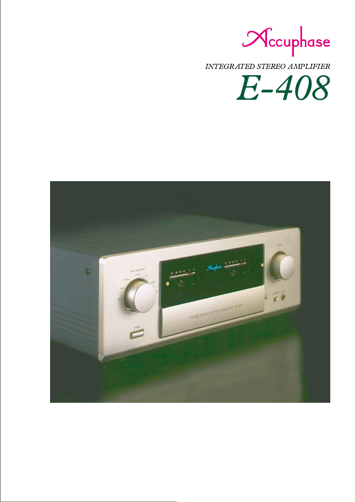
m Triple parallel push-pull output stage delivers high power: 180 watts
per channel into 8 ohms m Preamplifier and power amplifier with MCS
topology and current feedback m Logic-control relays permit straight
and short signal paths m T one control circuits m Ample power supply
with high-capacity R-toroidal transformer m Option board slots provide
capability for digital signal input or analog record playback
Page 2
High-output, high-performance integrated amplifier with MCS topology in
preamplifier and power amplifier stages. Current feedback ensures optimum
phase characteristics in high frequency range. Wide-band power transistors
in triple push-pull configuration and high-efficiency R-toroidal power
transformer deliver plenty of quality power: 260 watts per channel into 4
ohms or 180 watts into 8 ohms. Option boards can be used to implement
digital input or analog record playback with impeccable quality .
The E-408 is a further refined and enhanced
version of the highly popular and successful
E-407. Incorporating latest technology and
using only top quality parts, the E-408 is an
integrated amplifier that stands out through
sheer excellence. S/N ratio in the preamplifier
and power amplifier sections has been further
improved by the adoption of MCS (Multiple
Circuit Summing). Musical dynamics never
sounded so impressive, with every nuance
clearly outlined. The E-408 is the yardstick by
which integrated amplifiers will be measured
from now on.
Because an integrated amplifier has very high
overall gain, even the slightest interference or
crosstalk at the input can have a considerable
effect on the signal provided at the output. To
preclude this possibility, the E-408 is built with
totally separate preamplifier and power
amplifier sections. Both electrically and
structurally, these two parts operate completely
autonomously. Each has its own power supply
and dedicated regulator circuitry. A separate
set of inputs and outputs even allows using
the preamplifier and power amplifier as if they
were stand-alone components.
The circuits in the preamplifier and power
amplifier stages both use the MCS principle
as well as current feedback. MCS is a
sophisticated technique developed by
Accuphase for connecting multiple circuits in
parallel. The overall result of combining these
circuit topologies are improved performance
specs as well as superior sound quality. The
output stage of the power amplifier is
constructed as a triple parallel push-pull
configuration of multi-emitter type power
transistors designed for high-current audio
applications. The efficient R-toroidal power
transformer in the power supply and plenty of
filtering capacity support 260 watts per channel
(4 ohms) or 180 watts (8 ohms). The preamplifier
section features tone controls and a loudness
compensator designed to retain the purity of
the music signal. Functions such as recorder
Q
3a
Q
1a
Q
2a
Q
INPUT
4a
Q
3b
Q
1b
Q
2b
Q
4b
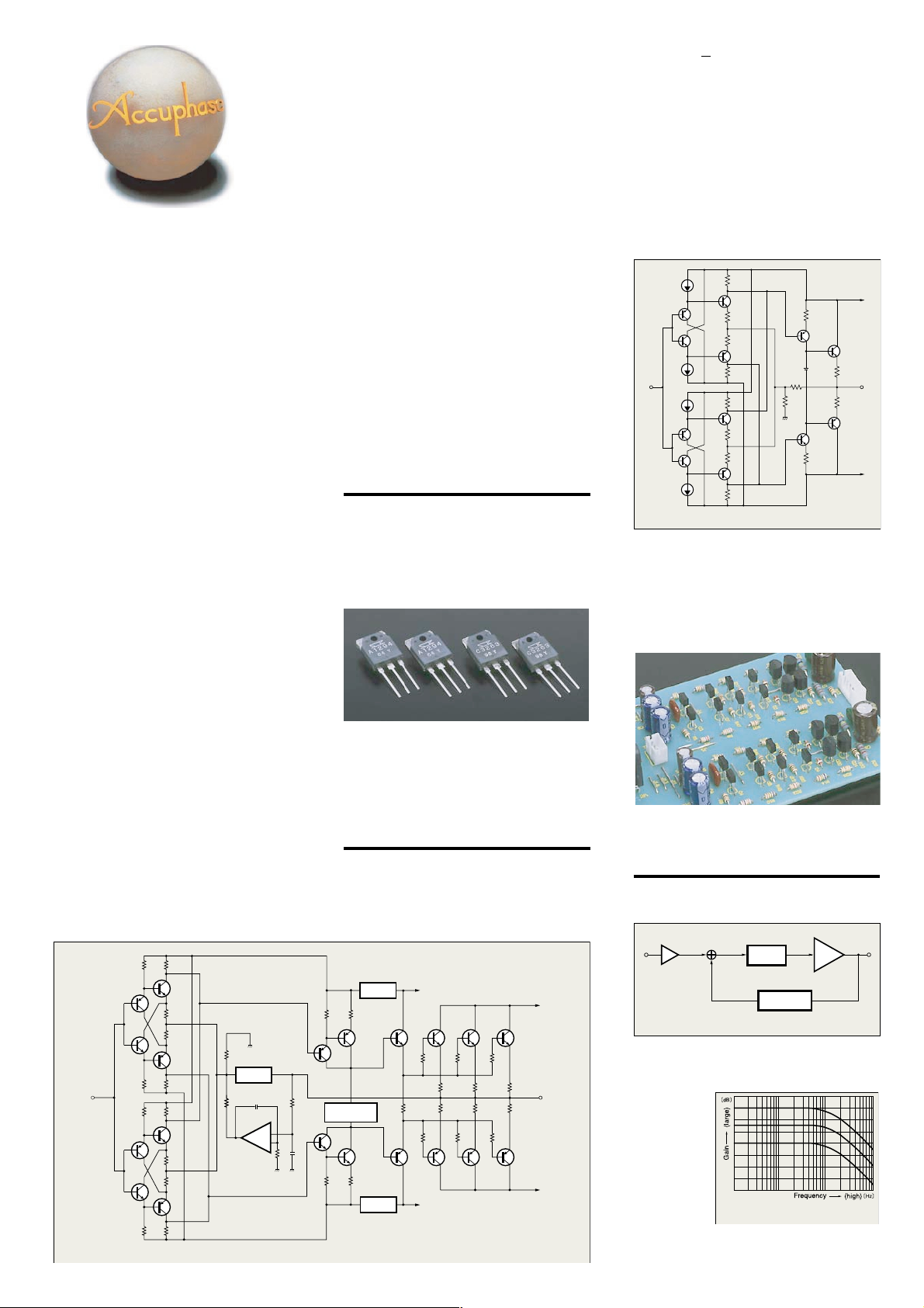
Fig. 1 Power amplifier circuit diagram (one channel)
NFB
NETWORK
+
–
monitoring and copying provide welcome
flexibility. All major parts were selected by strict
listening evaluation to assure a high all-round
standard of quality.
A Digital Input Board using a high-precision
MDS (Multiple Delta Sigma) D/A converter is
available as an option, allowing the digital signal
of a CD player or similar to be directly supplied
to the E-408. Another option is an Analog Disc
Input Board for high-grade reproduction of
analog records.
Triple parallel push-pull power unit delivers 260
watts/ch into 4 ohms, 220 watts/ch into 6 ohms,
and 180 watts/ch into 8 ohms
The power transistors used in the output stage are
multi-emitter devices designed for audio applications,
with optimum frequency response, forward-current
transfer ratio linearity, and switching performance
characteristics. By arranging these devices in a triple
parallel configuration (Figure 1), low impedance is
achieved. The transistors are mounted to a large
heat sink for efficient dissipiation of thermal energy.
As a result, the E-408 provides plenty of high-quality
output power.
Parallel connection MCS topology in preamplifier
and power amplifier stages
Both the power amplifier (Figure 1) and preamplifier
(Figure 2) employ the MCS (Multiple Circuit Summing)
topology developed by Accuphase. This design
results in significantly improved performance
characteristics such as higher S/N ratio and lower
Q
5
BIAS STABILIZER
Q
6
Q
CIRCUIT
Q
8
REGULA-
TOR
7
REGULA-
TOR
+
B
1
Q
9
Q
10
Q11Q13Q
Q12Q14Q
–
B
1
+
Q
7
OUTPUT
Q
8
B
-
B
INPUT
Q
1a
Q
3a
Q
Q
Q
Q
Q
4a
2a
1b
Q
3b
Q
4b
2b
5
Q
6
Fig. 2 Line amplifier circuit diagram
distortion. In the E-408, two separate amplification
circuits are fed the same signal, as well as the
feedback signal, and the output of the circuits is
combined, which is equivalent to parallel operation
of the overall circuit. Mathematically, when two
parallel circuits are employed, the improvement in
S/N ratio is 3 dB.
Current feedback circuit topology in power
amplifier and preamplifier sections prevents phase
shifts
In the E-408, the signal current rather than the more
conventionally used voltage is used for feedback.
Current
adder
Input
Buffer
+
B
2
15
Fig. 3 Current feedback amplifier principle diagram
I-V
converter
Trans-impedance
amplifier
Current NFB
network
Amplifier
Output
Because there is almost no phase shift, phase
compensation can be kept to a minimum, resulting in
OUTPUT
excellent
transient
response and
superb sonic
transparency.
16
–
B
2
Figure 4 shows
frequency
response for
different gain
settings of the
current
Fig. 4 Frequency response with current feedback
(response remains uniform even when gain changes)
feedback amplifier. The graphs demonstrate that
response remains uniform over a wide range.
Page 3
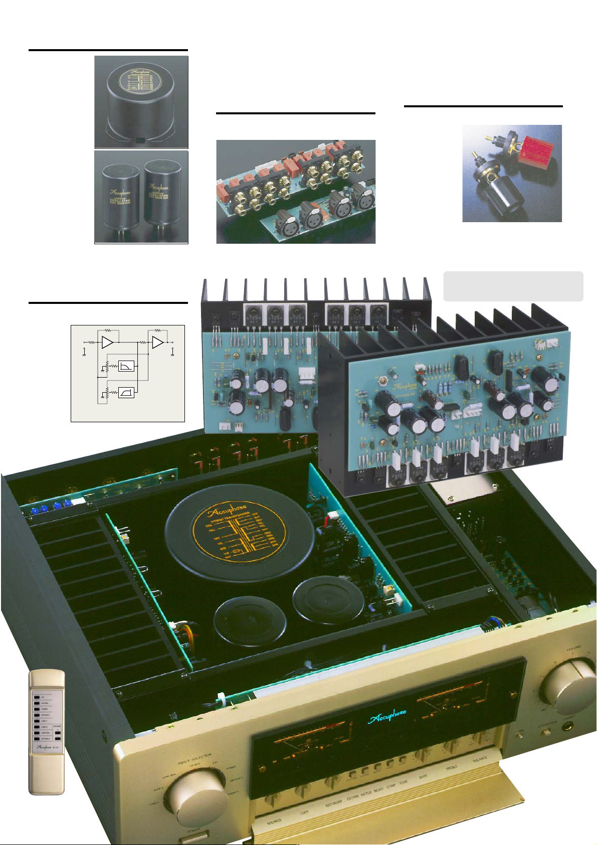
High-efficiency toroidal power transformer and high
filtering capacity
The power supply
section is a critical
aspect of any power
amplifier. The E-408
features a large toroidal power transformer with a rating
of 600 V A. The transformer is housed in
a non-resonant aluminum enclosure
filled with damping
material that has
excellent heat
transfer characteristics. Two large
33,000 µF capacitors smooth out any
current irregularities. This no-holdsbarred approach
manifests itself in
rock-solid, powerful sound even at ultra-deep frequencies.
Tone controls with summing active filters for
best sound
The tone control circuitry in the E-408 was specially
designed
with summing active
filters such
as found in
high-quality
graphic
equalizers.
Figure 5 illustrates the
operation
principle of
Input
–
A
1
F
1
VR
1
F
2
VR
2
Fig. 5 T one control principle
(Summing active filter type)
Output
–
A
2
this circuit. The flat signal is passed straight through,
and only when an adjustment is required, the characteristics are created at F
signal, thereby producing the desired change. This
1
and F2
and added to the
design provides efficient control without diluting signal purity.
Logic-controlled relays for signal switching assure
high sound quality and long-term reliability
All signal switching is performed by logic-controlled
relays which are arranged so as to permit the shortest
possible signal paths. The hermetically sealed relays
are high-quality types developed specifically for
demanding communication applications. The contacts
are twin crossbar types plated with gold for minimum
contact resistance and outstanding long-term
reliability.
Two sets of large size speaker terminals
The speaker terminals are made of extruded highpurity brass
material which
accept also
heavy-gauge
speaker cable.
Two sets of
outputs with a
speaker selector
are provided, and
bi-wiring
(supplying the
same signal via
dual leads to speakers with separate high-frequency
and low-frequency inputs) is also possible.
Output stage with triple parallel push-pull
arrangement, MCS, and current feedback
circuitry mounted to large heat sink
n Supplied remote
commander RC-20
allows volume
adjustment and input
source switching
Page 4
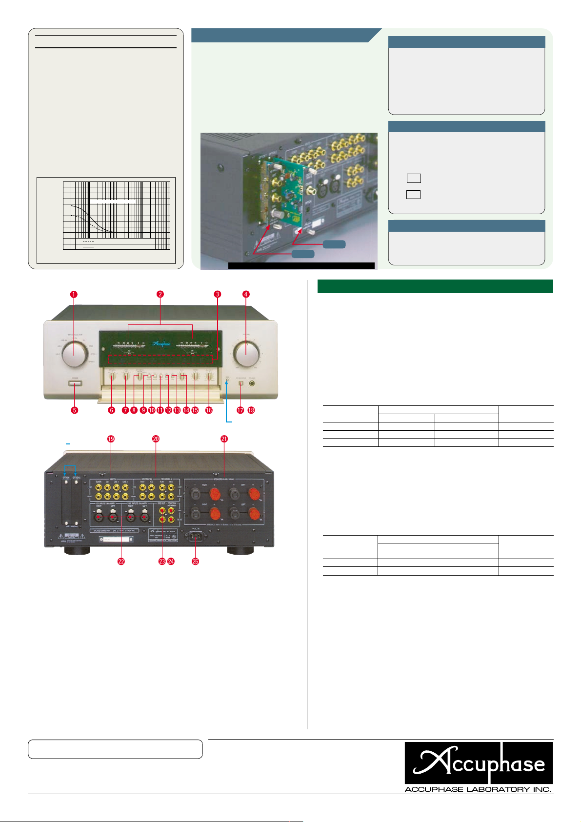
Other Functions and Features
n Digital input can be implemented via option board.
n Analog power meters
n High-quality volume control that can also be
operated via supplied remote commander
n “High Carbon” cast iron insulator feet with superior
damping characteristics further enhance sound
quality
n Dedicated headphone amplifier for optimum sound
n EXT PRE button and dedicated inputs/outputs
enable independent use of preamplifier and power
amplifier sections
n Loudness compensator restores natural balance at
low listening levels
18
16
14
12
10
8
6
4
2
0
Response in dB
–
2
–
4
–
6
10 100 1k 10k 100k
Compensator characteristics
LOUDNESS COMPENSATOR : ON
0dB : Volume Attenuation at – 20dB
0dB : Volume Attenuation at
Frequency in Hz
–
30dB
OPTION BOARDS
Three types of option boards are available for the E-408:
Digital Input Board DAC-10, Analog Disc Input Board AD-10,
and Line Input Board LINE-10.
m Two identical boards can also be installed.
m The Analog Disc Input Board AD-9 and Line Input
Board LINE-9 can also be used.
m The DAC-10 cannot be used in the models E-407,
E-406V, E-306V, E-211, and C-265.
DAC-10
AD-10
The photograph shows the E-408 with option boards installed.
Digital Input Board DAC-10
This board features an MDS (Multiple Delta Sigma)
D/A converter and has inputs for coaxial and optical
fiber connections.
It can accept the digital output signal from components such as
a CD player, MD recorder, DAT recorder, etc. (sampling
frequency range 32 - 96 kHz, 24 bits).
Analog Disc Input Board AD-10
This board contains a high-performance, high-gain
phono equalizer.
m Internal DIP switches control MM/MC operation, MC input
impedance, and subsonic filter on/off.
Gain : 36 dB
MM
Input impedance : 47 kΩ
Gain : 62 dB
MC
Input impedance : 10/30/100 Ω
(selectable)
Line Input Board LINE-10
This option board provides an additional set of
conventional line inputs which can be used to
connect a CD player, tuner, or other component
with analog output.
n Front panel
n Rear panel
Option Board
Slots
0
A
Input Selector
LINE2 LINE 1 LINE-BAL CD-BAL
CD TUNER OPTION 1 OPTION 2
B
Right/Left Channel Power Meters (dB scale/% indication)
C
Function LED Indicators
D
Volume Control
E
Power Switch
F
Speaker Selector OFF A B A+B
G
Copy Selector 1 ➝ 2 OFF 2 ➝ 1
H
Recorder Selector REC OFF SOURCE 1 2
I
EXT PRE (Preamplifier/Power Amplifier Separator)
ON/OFF Button
J
Meter Operation/Light Button
K
Stereo/Mono Button
Remarks
0
This product is available in versions for 120/230 V AC. Make sure that the voltage shown
on the rear panel matches the AC line voltage in your area.
0
The shape of the AC inlet and plug of the supplied power cord depends on the voltage
rating and destination country.
n Supplied accessories: • AC power cord
• Remote commander RC-20
L
Loudness Compensator Button
M
T one Control ON/OFF Button
N
Bass Control
O
T reble Control
P
Balance Control
Q
Attenuator Button
R
Headphone Jack
S
Line Input Connectors
T
Recorder Rec/Play Connectors
21
U
Left/Right Speaker Outputs
22
U
CD/LINE Balanced Input Connector
23
U
Preamplifier Output Connector
24
U
Power Amplifier Input Connectors
25
U
AC Power Supply Connector
Push to open sub panel
0
GUARANTEED SPECIFICATIONS
[Guaranteed specifications are measured according to EIA standard RS-490.]
m Continuous Average Output Power (both channels driven, 20 - 20,000 Hz)
m Total Harmonic Distortion (both channels driven, 20 - 20,000 Hz)
m Intermodulation Distortion 0.01%
m Frequency Response HIGH LEVEL INPUT/MAIN INPUT
m Damping Factor 120 (with 8-ohm load, 50 Hz)
m Input Sensitivity, Input Impedance
Input
HIGH LEVEL INPUT 158 mV 11.2 mV 20 kΩ
BALANCED INPUT 158 mV 11.2 mV 40 kΩ
MAIN INPUT 1.58 V 112 mV 20 kΩ
m Output Voltage, PRE OUTPUT: 1.58 V , 50 ohms
Output Impedance (at rated continuous average output)
m Gain HIGH LEVEL INPUT ➝ PRE OUTPUT: 20 dB
m Tone Controls T urnover frequency and adjustment range
m Loudness Compensation +6 dB (100 Hz) (Volume control setting –30 dB)
m Attenuator –20 dB
m Signal-to-Noise Ratio
Input
HIGH LEVEL INPUT 113 dB 82 dB
BALANCED INPUT 92 dB 82 dB
MAIN INPUT 129 dB 103 dB
m Power Level Meters Logarithmic compression, peak reading meters
m Load Impedance 4 - 16 ohms
m Stereo Headphones Suitable impedance: 8 - 100 ohms
m Power Requirements AC 120 V, 230 V (V oltage as indicated on rear panel) 50/60 Hz
m Power Consumption 55 watts idle
m Maximum Dimensions Width 475 mm (18-11/16”)
m Weight 23.4 kg (51.6 lbs) net
m Supplied Remote Commander RC-20
260 watts per channel into 4 ohms
220 watts per channel into 6 ohms
180 watts per channel into 8 ohms
0.02%, with 4 to 16 ohms load
2
0-120,000 Hz 0, –0.2 dB (for rated continuous average output)
02 - 150,000 Hz 0, –3.0 dB(for 1-watt output)
For rated output For 1 W output (EIA)
Sensitivity
Input impedance
MAIN INPUT ➝ OUTPUT: 28 d B
BASS: 300 Hz ±10 dB (50 Hz)
TREBLE: 003 kHz ±10 dB (20 kHz)
Input shorted (A weighting)
S/N ratio at rated output
Output dB/% scale
460 watts in accordance with IEC-65
Height 180 mm (7-1/16”)
Depth 422.7 mm (16-5/8”)
28.0 kg (61.7 lbs) in shipping carton
Remote control principle: infrared pulse
Power supply: 3 V DC (IEC R6 batteries x 2)
Maximum dimensions: 55 mm × 194 mm × 18 mm
Weight: 100 g (including batteries)
EIA S/N
• Specifications and design subject to change without notice for improvements.
F0305Y PRINTED IN JAP AN 851-0131-00 (AD1)http://www.accuphase.com/
 Loading...