

Page 1
INSTRUCTION MANUAL
MODE D’EMPLOI
BEDIENUNGSANLEITUNG
GEBRUIKSAANWIJZING
MANUALE DELLE ISTRUZIONI
Please read this manual and the separate Important Safety Instructions thoroughly before use, and retain these
documents for future reference.
Lire attentivement ce manuel et les consignes de sécurités importantes avant l’utilisation de cet appareil et conserver ces documents afi n de pouvoir y recourir ultérieurement.
Bitte lesen Sie sich diese Bedienungsanleitung und die beigefügten wichtigen Sicherheitshinweise vor der Inbetriebnahme des Gerätes sorgfältig durch und bewahren Sie diese Dokumente auf, um später jederzeit darauf
zurückgreifen zu können.
Lees deze gebruiksaanwijzing en de belangrijke veiligheidsinstructies in hun geheel door en bewaar beide documenten voor eventuele naslag in de toekomst.
Leggete attentamente sia questo manuale che le Importanti istruzioni di sicurezza separate prima dell’uso e
conservate questa documentazione per ogni futuro riferimento.
Page 2

Thank you for purchasing this Accuphase product, which is another manifestation of our efforts to create the
highest quality audio components. The strictest control was exercised throughout the entire manufacturing process
in producing this component – from basic research, the selection of each part, assembly, testing, data recording, up
to packing and shipping – so that we supply a product with every confi dence that it will provide full satisfaction and
pride in ownership.
We are pleased to heartily welcome you to the fast-growing Accuphase circle of distinguished audio enthusiasts and devotees of true sound.
ENGLISH
Nous vous remercions d’avoir fait l’achat de cet appareil Accuphase que nous vous présentons à titre
d’illustration de nos efforts dans la fabrication de composants audio aux critères haute fi délité les plus élevés. Le
montage de cet appareil est assuré avec les plus grands soins sous les plus rigoureux critères de qualité appliqués
à tous les niveaux de la production ; de l’étude fondamentale au choix délicat des composants, en passant par
l’assemblage, les essais, les résultats d’enregistrement, l’emballage et l’expédition. Ceci nous donne l’assurance
de vous envoyer un appareil parfait à tous points de vue, qui vous donnera entière satisfaction et dont vous serez
fi er d’être le possesseur.
FRANÇAISDEUTSCHNEDERLANDSITALIANO
Nous vous souhaitons la bienvenue dans le cercle grandissant des propriétaires d’appareils Accuphase, des
vrais audiophiles qui savent faire la différence.
Wir danken Ihnen, dass Sie sich für dieses Accuphase-Produkt entschieden haben. Sie können versichert sein,
dass unsere Mitarbeiter bei der Herstellung dieses Bausteins strengster Qualitätskontrolle besondere Beachtung
schenkten. Dasselbe gilt für den gesamten Herstellungsprozess von der Grundlagenforschung, Wahl der einzelnen
Teile, Montage, Prüfung, Datenaufzeichnung bis zur Verpackung und zum Versand, so dass wir unsere Hifi -Bausteine
mit der Überzeugung liefern können, dass diese hinsichtlich Klangqualität und Verarbeitung strengsten Ansprüchen
genügen.
Wir begrüßen Sie im schnell wachsenden Accuphase-Kreis anspruchsvoller Musikliebhaber und Anhänger
echter High Fidelity.
Hartelijk dank voor het aanschaffen van dit hoogwaardige Accuphase-product. U kunt ervan overtuigd zijn
dat dit product tijdens zijn vervaardiging voortdurend onderhevig was aan de strengste kwaliteitscontrole. Dit geldt
voor iedere stap in het productieproces – voorafgaande research, selectie van de onderdelen, assemblage, testen,
doormeten, verpakken en versturen – zodat wij er het volste vertrouwen in hebben dat dit product u volledige voldoening zal schenken.
Wij heten u verder van harte welkom in de snel groeiende Accuphase-kring van audiofanaten.
Vi ringraziamo per l’acquisto di questo prodotto Accuphase, un’ulteriore manifestazione dei nostri sforzi di
creare componenti audio della massima qualità. Durante ogni fase della sua fabbricazione – dalla progettazione,
selezione di ogni parte, montaggio, collaudo e registrazione dati, fi no all’imballaggio e alla spedizione – esso è stato
sottoposto ai più rigorosi controlli di qualità, in modo da poter garantire un prodotto di Vostra piena soddisfazione
che sarete fi eri di possedere.
Siamo lieti di accoglierVi nel sempre crescente circolo Accuphase, composto dai più esigenti appassionati
audio e alta fedeltà.
Page 3

Contents
WARNING / Accessories ...................................................................................2
Naming of Parts .................................................................................................3
Connection Diagram ..........................................................................................4
Parts and Functions ....................................................................................... 5, 6
Operation ......................................................................................................7 - 9
Option Boards / Optional Cables ............................................................... 10, 11
Remote Control ...............................................................................................12
Troubleshooting ............................................................................................... 12
Guaranteed Specifi cations ..............................................................................53
Performance Graphs .......................................................................................54
Block Diagram .................................................................................................55
This mark indicates an important instruction that must be observed to prevent the
About the R mark
possibility of death or injury to persons or severe damage to the unit. To ensure
safe use of the product, make sure that such instructions are fully understood
and observed.
WARNING:
Disregarding instructions bearing this mark incurs the risk of
R
death or severe injury.
CAUTION:
Disregarding instructions bearing this mark incurs the risk of
light injury or damage to the product.
ENGLISHFRANÇAISDEUTSCH
Table des matières
AVERTISSEMENT / Accessoires ......................................................................2
Nomenclature .................................................................................................... 3
Schéma de connexion ....................................................................................... 4
Pièces et fonctions .................................................................................. 13, 14
Fonctionnement ........................................................................................15 - 17
Cartes optionnelles / Câbles optionnels ....................................................18, 19
Télécommande ................................................................................................ 20
Localisation des pannes .................................................................................. 20
Spécifi cations garanties ...................................................................................53
Courbes des résultats ...................................................................................... 54
Schéma simplifi é .............................................................................................55
Inhalt
WARNUNG / Zubehör .......................................................................................2
Bezeichnung der Teile .......................................................................................3
Anschlussdiagramm ..........................................................................................4
Bauteile und Funktionen ...........................................................................21, 22
Bedienung ................................................................................................23 - 25
Zusatzplatinen / Optionale Kabel ............................................................... 26, 27
Fernbedienung ................................................................................................28
Fehlersuche .....................................................................................................28
Garantierte technische Daten ..........................................................................53
Leistungskurven .............................................................................................. 54
Blockschaltbild .................................................................................................55
Inhoudsopgave
WAARSCHUWING / Accessoires ...................................................................... 2
Benaming van de onderdelen ............................................................................ 3
Verbindingsdiagram ...........................................................................................4
Onderdelen en functies ............................................................................29, 30
Bediening ..................................................................................................31 - 33
Optionele kaarten / Optionele kabels ........................................................34, 35
Afstandsbediening ........................................................................................... 36
Oplossing van problemen ................................................................................36
Gegarandeerde technische gegevens ............................................................. 53
Prestatiecurves ................................................................................................ 54
Blokschema ..................................................................................................... 55
Ce signe indique une instruction importante qui doit être respectée pour éviter
d’entraîner des blessures graves ou mortelles ou d’endommager sérieusement
l’appareil. Pour une utilisation du produit en toute sécurité, s’assurer de bien
comprendre les instructions et de les respecter.
AVERTISSEMENT :
Ne pas respecter les instructions accompagnées de ce signe
risque d’entraîner la mort ou des blessures graves.
R
ATTENTION :
Ne pas respecter les instructions accompagnées de ce signe
risque d’entraîner des blessures légères ou d’endommager
le produit.
Wissenswertes über das Zeichen R
A propos du signe R
Dieses Zeichen weist auf wichtige Anweisungen hin, deren Nichtbeachtung
möglicherweise lebensgefährlich ist bzw. Verletzungen oder schwerwiegende
Geräteschäden verursachen kann. Stellen Sie für eine sichere Verwendung
die ses Gerätes sicher, dass diese Anweisungen sowohl vollständig verstanden
als auch befolgt werden.
WARNUNG:
Eine Nichtbeachtung der mit diesem Zeichen gekennzeichneten Anweisungen kann lebensgefährlich sein und schwere
Verletzungen verursachen.
R
VORSICHT:
Eine Nichtbeachtung der mit diesem Zeichen gekennzeichneten Anweisungen kann leichte Verletzungen oder Geräteschäden verursachen.
Het teken R
Dit teken wijst op een belangrijke richtlijn die moet worden gevolgd om het
risico op dood, letsels of ernstige schade aan het toestel te vermijden. Deze
richtlijnen moeten volledig worden begrepen en gevolgd om een veilig gebruik
van dit toestel te verzekeren.
WAARSCHUWING:
Niet-naleving van richtlijnen voorafgegaan door dit symbool
R
kan leiden tot de dood of tot ernstige letsels.
OPGELET:
Niet-naleving van richtlijnen voorafgegaan door dit symbool
kan leiden tot lichte letsels of schade aan het product.
NEDERLANDS
Sommario
AVVERTIMENTO / Accessori ............................................................................2
Nomenclatura dei componenti ...........................................................................3
Schema dei collegamenti ..................................................................................4
Parti e funzioni ...........................................................................................37, 38
Funzionamento .........................................................................................39 - 41
Schede opzionali / Cavi opzionali ..............................................................42, 43
Telecomando ................................................................................................... 44
Localizzazione dei guasti ................................................................................. 44
Specifi che garantite ......................................................................................... 53
Curve delle prestazioni .................................................................................... 54
Diagramma a blocchi .......................................................................................55
Questo simbolo indica importanti istruzioni che vanno seguite onde evitare il
Informazioni sul simbolo R
rischio di lesioni mortali o gravi alle persone o gravi danni all’unità. Per assicurare
un uso sicuro del prodotto, assicuratevi che tali istruzioni siano capite e osservate
in maniera assoluta.
AVVERTIMENTO:
L’inosservanza delle istruzioni che recano questo simbolo e questa
dicitura comporta rischi di lesioni gravi o addirittura mortali.
R
ATTENZIONE:
L’inosservanza delle istruzioni che recano questo simbolo e questa
dicitura comporta rischi di lesioni non gravi o danni materiali al
prodotto.
ITALIANO
1
Page 4

RWARNING
Before starting to use the unit, carefully read the separate
Instructions
■ Be sure to connect the power cord of the E-350 only to an AC outlet rated for the
voltage shown on the rear panel.
■ Never use any other power cord except the supplied cord.
■ Be sure to connect the power cord only to an AC outlet with protective earthing
connection.
■ Opening the unit is dangerous.
■ Do not place the unit in an enclosed rack without any means of fresh air ventilation.
Otherwise it could overheat, resulting in the risk of fi re and damage to the unit.
■
To reduce the risk of fi re or electric shock, do not expose the unit to rain or moisture.
to ensure correct use.
Important Safety
RAVERTISSEMENT
Avant de commencer à utiliser l’appareil, lire attentivement les
de sécurité importantes
■ S’assurer de brancher le cordon d’alimentation du E-350 uniquement sur une prise CA
correspondant à la tension indiquée sur le panneau arrière.
■ Ne jamais utiliser d’autre cordon d’alimentation que celui fourni.
■ Veiller à ne brancher le cordon d’alimentation qu’à une prise CA reliée à la terre.
■ Il est dangereux d’ouvrir l’appareil.
■ Ne pas placer l’appareil dans une étagère fermée sans ventilation. Sinon il risque de
surchauffer, de provoquer un incendie et d’être endommagé.
■ Afi n de réduire les risques d’incendie et d’électrocution, ne pas exposer cet appareil à la
pluie ou à l’humidité.
Afi n d’assurer une dissipation correcte de la chaleur, laisser suffi samment d’espace (au moins
■
pour garantir une bonne utilisation.
Consignes
RWARNUNG
Lesen Sie vor der Inbetriebnahme des Gerätes bitte die separaten
Wichtigen Sicherheitshinweise
sicherzustellen.
■ Schließen Sie das Netzkabel des E-350 ausschließlich an eine Wechsel strom-Netzsteckdose
mit der auf der Rückseite des Gerätes ange gebenen Spannung an.
■ Verwenden Sie niemals ein anderes als das im Lieferumfang enthaltene Netzkabel.
■ Schließen Sie das Netzkabel ausschließlich an eine Wechselstrom-Netzsteckdose mit einem
Schutz-Erdungsanschluss an.
■ Das Öffnen des Gerätes ist gefährlich.
■ Stellen Sie das Gerät niemals in einem geschlossenen Regal ohne Frisch luftzufuhr auf.
Anderenfalls könnte es sich überhitzen, was zum Entstehen eines Brandes oder einer
Beschädigung des Gerätes führen könnte.
■ Um das Risiko eines Brandes oder eines elektrischen Schlages zu verringern, setzen Sie
das Gerät weder Regen noch Feuchtigkeit aus.
, um eine ordnungsgemäße Verwendung
RWAARSCHUWING
Lees voor gebruik de afzonderlijke
zeker te zijn van een correct gebruik van het toestel.
■ Sluit het netsnoer van de E-350 uitsluitend aan op een stopcontact dat de op het achterpaneel
aangegeven voedingsspanning heeft.
■ Maak uitsluitend gebruik van het bijgeleverde netsnoer.
■ Sluit het netsnoer alleen aan op een stopcontact met beschermende aardaansluiting.
■ Het openen van de behuizing is gevaarlijk.
■ Plaats het toestel niet in een gesloten rek zonder goede ventilatie. Dit kan oververhitting
veroorzaken en leiden tot brandgevaar en beschadiging van het toestel.
■ Stel dit toestel niet bloot aan regen of vocht om gevaar voor brand en elektrische schokken
te verkleinen.
Belangrijke veiligheidsinstructies
om
■ To ensure proper heat dissipation, leave suffi cient clearance (at least 10 cm) between
the unit and other components and surrounding walls, etc.
■ Do not operate the EXT PRE button during playback.
Always turn the volume fully down before setting the switch to ON or OFF.
■ Be sure to turn power off before connecting anything to the POWER IN jacks.
Accessories
● Instruction manual ................................................................... 1
● Important Safety Instructions...................................................1
● Remote commander RC-200 ................................................. 1
● IEC R03 (size AAA) battery .................................................... 2
● AC power cord (2 m) ..............................................................1
10 cm) entre l’appareil et les autres composants ainsi que les murs environnants, etc.
■ Ne pas utiliser la touche EXT PRE pendant la lecture.
Toujours réduire le volume au minimum avant de mettre l’interrupteur en position ON ou OFF.
■ S’assurer d’éteindre l’appareil avant de connecter un autre appareil aux prises POWER IN.
Accessoires
● Mode d’emploi .........................................................................1
● Consignes de sécurité importantes .........................................1
● Télécommande RC-200 ........................................................... 1
● Pile IEC R03 (format AAA) .....................................................2
● Cordon d’alimentation CA (2 m) .............................................1
■ Lassen Sie bitte ausreichend Raum (mindestens 10 cm) zwischen dem Gerät, anderen
Komponenten und umgebenden Wänden o. Ä., um eine ordnungsgemäße Wärmeableitung
sicherzustellen.
■ Betätigen Sie die EXT PRE-Taste nicht während der Wiedergabe.
Drehen Sie die Lautstärke immer ganz herunter, bevor der Schalter auf ON oder OFF gestellt
wird.
■ Stellen Sie sicher, dass Sie die Stromversorgung ausschalten, bevor Sie irgendein Gerät an
die POWER IN-Buchsen anschließen.
Zubehör
● Bedienungsanleitung ............................................................... 1
● Wichtige Sicherheitshinweise ..................................................1
● Fernbedienung RC-200 ..........................................................1
● IEC R03-Batterien (Größe AAA) ............................................. 2
● Wechselstrom-Netzkabel (2 m) ...............................................1
■ Houd voldoende ruimte (tenminste 10 cm) tussen het toestel en de overige componenten
of nabij gelegen wanden, e.d., zodat u verzekerd bent van een goede warmteafvoer.
■ Bedien de EXT PRE-toets niet tijdens de weergave.
Stel het volume altijd op de minimumstand in voordat u deze toets op ON of OFF zet.
■ Schakel de spanning uit voordat u aansluitingen op de POWER IN-aansluitingen maakt.
Accessoires
● Gebruiksaanwijzing ................................................................. 1
● Belangrijke veiligheidsinstructies ............................................. 1
● Afstandsbediening RC-200 ....................................................1
● IEC R03-batterij (AAA-formaat) .............................................. 2
● Netsnoer (2 m) ........................................................................1
RAVVERTIMENTO
Prima di usare l’unità, leggete attentamente le
separate per assicurarne l’uso corretto.
sicurezza
■ Assicuratevi di collegare il cavo di alimentazione del modello E-350 solo ad una presa a
mura CA che fornisce il voltaggio nominale indicato sul pannello posteriore.
■ Non usate mai cavi d’alimentazione diversi da quello in dotazione.
■ Assicuratevi di collegare il cavo di alimentazione solo ad una presa CA con messa a terra.
■ L’apertura dell’unità può essere molto pericolosa.
■ Non posizionate l’unità in un mobile chiuso senza una ventilazione adeguata. In caso
contrario, l’unità si può surriscaldare, con rischi di incendio e danni alla stessa.
■ Per ridurre il rischio di scosse elettriche, non esponete l’unità a pioggia o umidità.
■ Per garantire un’adeguata dispersione del calore, lasciare spazio suffi ciente (almeno 10 cm)
tra l’unità e altri componenti o muri circostanti ecc.
2
Importanti istruzioni di
■ Non utilizzate il tasto EXT PRE durante la riproduzione.
Girate sempre il comando del volume completamente verso il basso prima di posizionare
l’interruttore su ON o OFF.
■ Assicuratevi di spegnere l’alimentazione prima di collegare i componenti alle prese POWER
IN.
Accessori
● Manuale delle istruzioni ........................................................... 1
● Importanti istruzioni di sicurezza ............................................. 1
● Telecomando RC-200 ..............................................................1
● Batteria IEC R03 (dimensione AAA) ...................................... 2
● Cavo di alimentazione CA (2 m) ..............................................1
Page 5
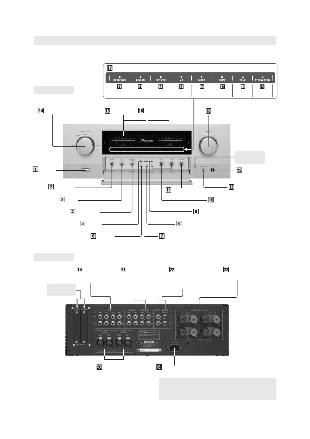
Naming of Parts
Display section ★ LED indicators show operation status
Front panel
Recorder
is playing
Recording
is possible
power amplifi er
INPUT SELECTOR Power meters Remote sensor
POWER
switch
SPEAKER
selector
COPY
selector
RECORDER
selector
MC/MM
(phono stage gain) selector
EXT PRE
(preamplifi er/power amplifi er
separator) button
Preamplifi er/
are separated
MC position
is selected
BALANCE
control
METER
display on/off button
MONO
(mono/stereo selector) button
Monophonic
operation
is selected
Loudness
compensator
is ON
VOLUME control
Tone controls
TONE ON/OFF button
COMP
BASS, TREBLE controls
(loudness compensator)
button
Tone controls
are ON
Attenuator
is ON
Push here to
open sub panel
PHONES
jack
ATTENUATOR button
Rear panel
Option board
slots
INPUTS
TUNER, CD,
LINE 1, 2
CD/LINE INPUTS
(BALANCED)
RECORDER 1, 2
Recorder Input/Output
jacks
AC Inlet
Remark
This product is available in versions for 120/230 V AC. Make
sure that the voltage shown on the rear panel matches the
AC line voltage in your area.
PRE OUT/
POWER IN
(EXT PRE IN)
jacks
SPEAKERS
terminals (A, B)
3
Page 6
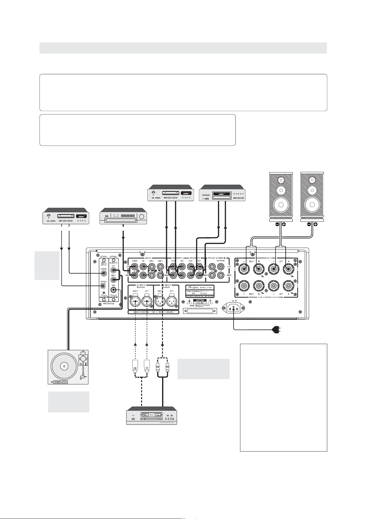
Connection Diagram
R
CAUTION:
Before making connections, be sure to switch the power to all components off.
Note:
● For connection between DAC-20 and digital equipment, use a digital coaxial cable or optical fi ber cable.
● For analog input/output connections, use shielded audio cables and take care not to mix up left and right channels.
● Do not make connections to a component with balanced and unbalanced cables at the same time. Otherwise ground loops
may occur which can cause noise.
The illustration shows a connection example for the unit, with separately available option
boards installed. (For information on option board types, see “Option Board types”.)
● OPTION 1: Digital Input Board DAC-20
● OPTION 2: Analog Disc Input Board AD-20
CD player, MD recorder,
or other digital
component
Optical fi ber
cable
Digital coaxial
cable
ANALOG OUTDIGTAL OUT
Tuner
Recorder 1
LINE OUT LINE IN LINE OUT LINE IN
Recorder 2
Speakers
Left
Right
For an
explanation
of the digital
input, see
“Option
Boards”
Record player
For an explanation of
analog disc playback,
see “Analog disc
(AD) playback”.
Balanced
cable
ANALOG
OUTPUTS
CD Player
Audio cable
with plug
✽ Use shielded cables for
audio connections (2-conductor shielded cables for
balanced connections).
AC power cord (supplied)
Be sure to plug this cord only into an AC outlet rated
for the same voltage as shown on the rear panel.
Cordon d’alimentation secteur (fourni)
Brancher ce cordon uniquement dans une prise
secteur ayant la même tension nominale qu’indiqué
sur le panneau arrière.
Wechselstrom-Netzkabel (im Lieferumfang
enthalten)
Verwenden Sie dieses Netzkabel nur bei
Netzsteckern mit der gleichen Spannung wie auf der
Geräte-Rückseite angegeben.
Netsnoer (bijgeleverd)
Steek dit snoer enkel in een stopcontact waarvan de
spanning identiek is aan die op het achterpaneel.
Cavo di alimentazione CA (in dotazione)
Assicuratevi di collegare questo cavo solo ad una
presa murale CA che fornisce il voltaggio nominale
indicato sul pannello posteriore.
4
Page 7

Parts and Functions
POWER – Power switch
Depress this switch to activate the amplifi er. Push once more to release
1
the switch and turn the amplifi er off. For an interval of about 5 seconds
after power is turned on, there will be no sound from the speakers, due
to the action of the muting circuit.
● After turning the power off, do not set the power switch immediately to ON
again (within 10 seconds).
SPEAKER – Speaker selector
Serves to select two pairs of speakers connected to the “A” and “B”
2
speaker terminals.
OFF
Both speaker pairs are turned off, for example for headphone listening.
A, B
The respective speaker pair is active.
A + B
Both pairs of speakers are driven simultaneously. In this case, use speakers with
a rated impedance of 4 ohms or more, as both sets are connected in parallel.
This position is also used for biwiring a single set of loudspeakers (using
separate cables for the low frequency range and mid/high frequency range).
COPY – Copy selector
When two recorders are connected to the E-350, dubbing can be carried
3
out in either direction by using this selector.
1 2, 2 1
To use the recorder connected to the RECORDER 1 jacks on the rear panel
as source and the recorder connected to the RECORDER 2 jacks as recorder,
set the selector to “1 2”. For dubbing in the opposite direction, use the
“2 1” position.
OFF
Set the selector to this position when dubbing is not desired.
RECORDER – Recorder selector
4
REC OFF
Select this position in normal operation (when not recording). The amplifi er
reproduces the selected program source, but the signal does not appear at
the REC outputs.
– “REC ON” LED lit
SOURCE
Select this position when wishing to record. The amplifi er reproduces the
selected program source, and the signal appears at the REC outputs.
– “RECORDER” and “REC ON” LEDs lit
1, 2
Select this to reproduce the signal from a recorder.
Select the position depending on the rear-panel “PLAY” input (RECORDER 1
or RECORDER 2) that is used.
MC/MM – MC/MM selector button
5
This function is only available when the Analog Disc Input Board
AD-20 is installed.
This selector button determines the phono stage gain for playback of analog
discs (phono records) with the AD-20.
● Button pressed (MC): “MC” LED is lit
● Button pressed once more (MM): “MC” LED is out
MC
This position should be used for moving-coil (MC) cartridges with low output.
Set the input impedance with the DIP switches on the board.
MM
This position should be used for moving-magnet (MM) cartridges. The input
impedance is 47 kilohms.
Note:
● MC/MM switching becomes available when the INPUT SELECTOR
set to the position for an option board slot where the AD-20 is installed.
● For MC/MM switching, the setting of the MC/MM selector
The AD-20 has DIP switch settings for MC/MM selection, but the board
settings are overridden by the selector of the E-350.
The MC LOAD and FILTER settings are made only on the AD-20 board.
●
There are no provisions for setting these items at the E-350.
● The Analog Disc Input Board AD-9 or AD-10 can also be used, but in this
case, MC/MM selection can only be made on the board. The setting of the
MC/MM selector of the E-350 has no effect.
EXT PRE – Preamplifi er/power amplifi er separator button
This button permits using the preamplifi er section and the power amplifi er
6
section of the E-350 separately.
5
is
14
has priority.
● Button pressed (ON): “EXT PRE” LED is lit
Preamplifi er and power amplifi er are separated.
● Button pressed once more (OFF): “EXT PRE” LED is out
Normal operation, preamplifi er and power amplifi er not separated.
Note:
Do not operate the switch during playback. Always turn the volume fully down
before setting the switch to ON or OFF.
MONO – Mono/stereo mode selector button
This switch selects stereo or mono operation. When the switch is pressed,
7
both channels are combined and the same signal is fed to the left and
right speakers. If the listening position is at approximately equal distance
from the speakers, the sound image should be centered.
● Button pressed (monophonic operation): “MONO” LED is lit
Button pressed once more (stereo operation): “MONO” LED is out
●
Note:
When the RECORDER selector setting is changed to “SOURCE”, the
monophonic setting will automatically be canceled. To record in monophonic
mode, press the MONO button again after using the RECORDER selector.
METER – Meter display on/off button
8
● Button pressed (OFF):
Meter lights are out and meters do not operate.
● Button pressed once more (ON):
Meter lights are on and meters operate.
COMP – Loudness compensator button
This button serves to restore natural tonal balance at low listening levels.
9
The human ear becomes less sensitive for the frequency extremes as
loudness decreases. This often causes the sound to be perceived as thin or
defi cient, especially in the bass range. The COMP button makes up for this effect
by boosting the lower range (+6 dB at 100 Hz).
● Button pressed (ON): “COMP” LED is lit
● Button pressed once more (OFF): “COMP” LED is out
TONE (BASS, TREBLE) – Tone controls
10
TONE – Tone control on/off button
● Button pressed (ON): “TONE” LED is lit
● Button pressed once more (OFF): “TONE” LED is out
✽ When the button is set to ON, the BASS and TREBLE controls can be
used.
✽ When the button is set to OFF, the entire tone control circuitry is by-
passed.
– Bass control
BASS
Turning this control to the right from the center (0) position boosts the lower
frequency range and turning the control to the left attenuates it.
● Turnover frequency: 300 Hz
● Adjustment range: ±10 dB at 50 Hz
– Treble control
TREBLE
Turning this control to the right from the center (0) position boosts the upper
frequency range and turning the control to the left attenuates it.
● Turnover frequency: 3 kHz
● Adjustment range: ±10 dB at 20 kHz
BALANCE – Balance control
This control serves to adjust the left/right stereo balance.
11
● Normally, the control should be left in the center (0) position.
ATTENUATOR – Attenuator button
Pressing the ATTENUATOR button will quickly reduce the volume level
12
of the amplifi er to one-tenth (-20 dB attenuation).
● Button pressed (ON): “ATTENUATOR” LED is lit
● Button pressed once more (OFF): “ATTENUATOR” LED is out
ENGLISH
5
Page 8
PHONES – Headphone jack
Stereo headphones can be plugged into this jack.
13
✽ When wishing to listen with headphones only, set the SPEAKERS selector to
ENGLISH
OFF.
✽ Adjust the listening level with the main volume control.
✽ Use headphones with an impedance between 8 and 100 ohms.
Note:
When the preamplifi er and power amplifi er sections have been separated
by setting the EXT PRE button to ON, this headphone jack carries the same
signal as the power amplifi er section of the E-350. The volume therefore must
be adjusted at the external preamplifi er.
INPUT SELECTOR – Input selector
Serves to select the various program sources connected to the rear
14
panel inputs. The corresponding buttons on the remote commander
RC-200 can also be used.
TUNER, CD, LINE 1, 2
Selects components connected to the conventional unbalanced inputs (for
unbalanced audio cable with plugs) on the rear panel.
CD-BAL, LINE-BAL
Selects components connected to the balanced inputs (for balanced audio
cable) on the rear panel.
OPTION 1, 2
Select components connected to option boards installed in the OPTION 1 and
OPTION 2 slots on the rear panel.
● For information on option boards, see “Option boards”.
✽ The INPUT SELECTOR has no marking or end stopper (it can be turned
continuously).
Peak power meters
The meter scale indicates the output level in dB (decibel) and is also
15
calibrated in watts for an 8-ohm load. With a 4-ohm load, the fi gures
must be doubled, and with a 16-ohm load halved. Output levels with a
sine-wave signal for various loads are shown below.
Output indication
(dB/%)
0 dB: 100 % 200 W 100 W 50 W
–10 dB: 10 % 20 W 10 W 5 W
–20 dB: 1 % 2 W 1 W 500 mW
–30 dB: 0.1 % 200 mW 100 mW 50 mW
–40 dB: 0.01 % 20 mW 10 mW 5 mW
The meters are peak-reading designs, which enables them to precisely follow the
rapid changes in amplitude and frequency that are common with music signals. To
make for easier reading, the decay time of the meters is set to a lower value than
the rise time. If the program source contains noise or a large amount of transients,
the meter indication and the aural volume impression may differ slightly.
Remote sensor
The infrared signals from the supplied remote commander RC-200 are
16
received by this sensor. When using the remote commander, point the
transmitter in the direction of this sensor.
Display section
The operation status of various buttons and controls is shown by the
17
on/off status of the LEDs on this panel.
LED lit Operation status
RECORDER
REC ON RECORDER selector: SOURCE 1, 2 (Recording is possible)
EXT PRE button: ON
EXT PRE
(Preamplifi er/power amplifi er are separated)
MC MC/MM button: MC
MONO MONO button: ON (Monophonic operation is selected)
COMP COMP button: ON (Loudness compensator is selected)
TONE BASS, TREBLE: Tone controls are active
ATTENUATOR
18
Note:
When changing the setting of the EXT PRE button, when changing program
sources, and when switching the power on and off, the volume control should
always be turned fully down.
ATTENUATOR button: ON (Attenuator function is active)
VOLUME – Volume control
Turning this control clockwise increases the listening level. The control
can also be operated with the remote commander RC-200.
4-ohm load 8-ohm load 16-ohm load
RECORDER selector: 1, 2 (Recorder is playing)
4
4
6
5
7
9
10
12
The E-350 incorporates an innovative volume control called AAVA-II
(Accuphase Analog Vari-gain Amplifi er-II). The operation principle of this
control is totally different from conventional controls using resistors. With
AAVA-II, the music signal is weighted in 16 stages, and a current switching
circuit serves to select the signal, thereby changing the volume.
In actual operation, a conventional rotary VR is used. When the
knob is turned, its position is detected by the adjustment circuit, and 16 current
switches are set to ON or OFF accordingly.
Note:
When high-effi ciency loudspeakers are used, a sound caused by the current
switch operation may be heard when turning the VOLUME knob. This is not
a defect.
INPUTS: TUNER, CD, LINE 1, LINE 2 – Line-level inputs
These inputs are conventional unbalanced line input jacks.
19
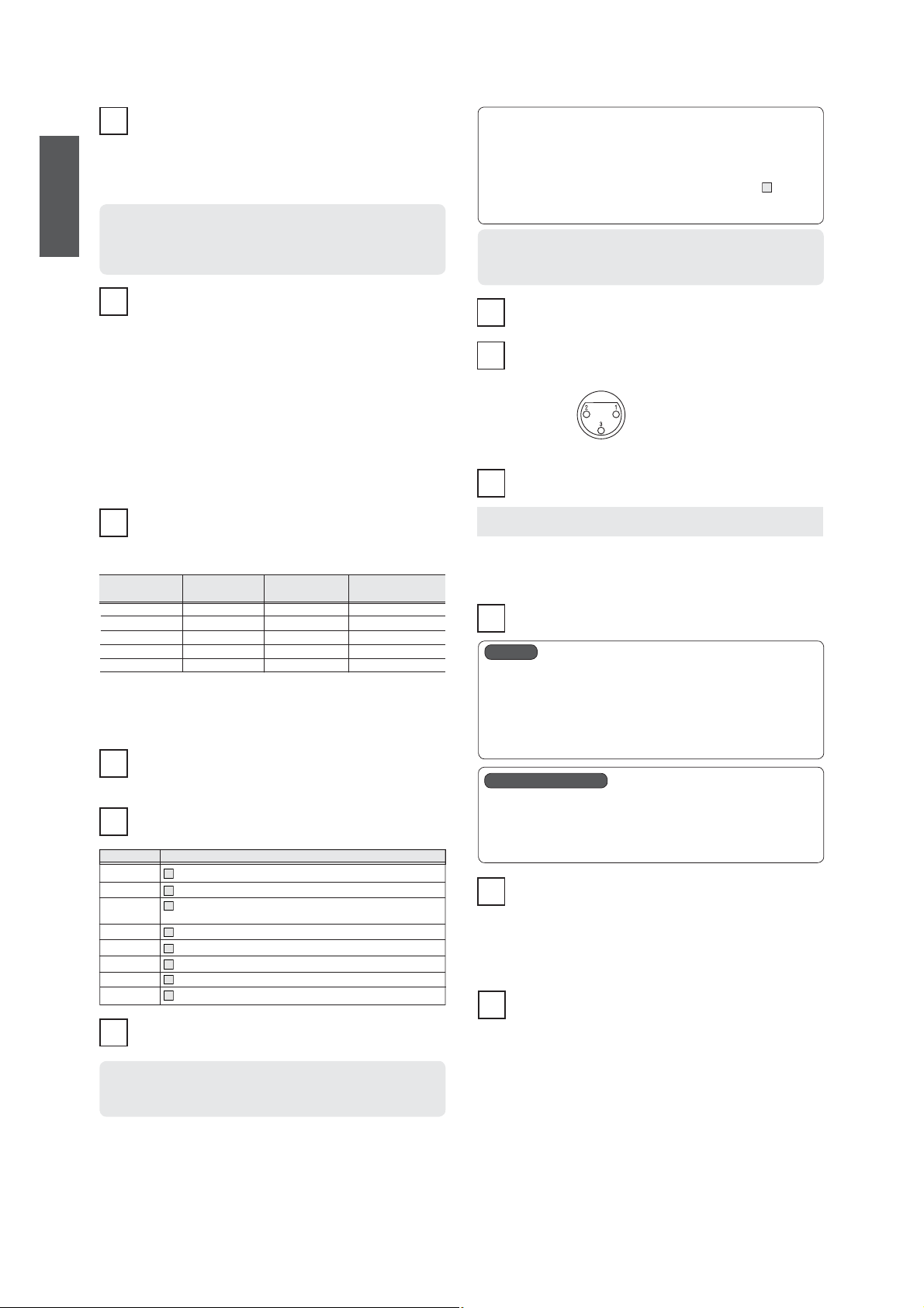
CD/LINE INPUTS (BALANCED) – Balanced inputs
These are inputs for a balanced connection which eliminates externally
20
induced noise. The inputs accept the signal of any component with
balanced outputs, such as a CD player or tuner.
A: Ground
B: Inverted (–)
C: Non-inverted (+)
● Balanced audio cables are available from Accuphase.
RECORDER 1, 2 – Recorder input/output jacks
These jacks serve for connection of two recorders.
21
PLAY jacks Ù LINE OUT jacks of recorder
REC jacks Ù LINE IN jacks of recorder
✽ The output signal at the REC jacks is not affected by the volume and tone
controls, or compensator settings of the amplifi er.
✽ Keep in mind that when the MODE switch is set to “MONO”, the recording
output will be monophonic.
What is AAVA-II?
18
VOLUME
PRE OUT/POWER IN (EXT PRE IN) jacks
22
PRE OUT
These jacks permit using the preamplifi er section separately.
● The signal at these jacks is always output, regardless of the setting of the
EXT PRE button.
● The outputs can be used to connect a second power amplifi er for biamping.
Bi-amping refers to using separate power amplifi ers for the low frequency range
✽
and mid/high frequency range.
POWER IN (EXT PRE IN)
These jacks permit using the power amplifi er section separately.
● When the EXT PRE button has been set to “ON” for separating the
preamplifi er and power amplifi er of the E-350, these jacks serve as power
amplifi er input jacks. Input source switching, volume adjustment, and other
preamplifi er functions must be performed at the external equipment.
SPEAKERS terminals (A, B)
Two pairs of speakers can be connected to the terminals A and B.
23
✽ Use speakers with a rated impedance of 4 to 16 ohms.
✽ When driving two pairs of speakers simultaneously, use speakers with a rated
impedance of 8 to 16 ohms.
✽ For a biwiring arrangement, connect the cables for the low frequency range
and mid/high frequency range separately to terminals A and B.
AC Inlet
Insert the supplied power cord into this connector and plug the other
24
end into an AC outlet.
6
Page 9

RWARNING
● Do not use the unit with any other than the supplied power cord.
● The shape of the AC inlet and the plug of the supplied power cord depend
on the destination country of the unit. Using any other type of cable except
the supplied power cord poses the risk of fi re and damage.
● This product is available in versions for 120/230 V AC. Make sure that
the voltage shown on the rear panel matches the AC line voltage in your
area.
Operation
● Opening the unit involves a severe risk of electric shock.
● If the unit does not operate, the internal fuse may have blown. Never
attempt to replace the fuse yourself. Be sure to contact your Accuphase
dealer or an authorized service station.
R CAUTION
● Before making connections, be sure to switch the power to the E-350 and all other components off. Especially when plugging or
unplugging a cable in the POWER IN jacks, the power to the E-350 must be off.
● Do not operate the EXT PRE button during playback. Always turn the volume fully down before setting the switch to ON or OFF.
Before starting to use the unit, set the controls as follows.
● VOLUME: Turned fully down (counterclockwise)
● SPEAKER: Set to the position for the desired speaker pair
● RECORDER: REC OFF (LED out)
● COPY: OFF
● MC/MM, MONO, COMP, EXT PRE, ATTENUATOR: OFF (LEDs out)
● BALANCE: Center position
Listening to a CD player (via analog input)
Connect the analog output of the CD player to the CD (or TUNER or LINE) input
jacks on the rear panel. If the CD player has balanced outputs, it is recommended
to use balanced cables and connect them to the balanced CD/LINE INPUTS
connectors.
For playback, perform the following steps.
A Confi rm that the VOLUME control is turned to minimum. Then switch on the
CD player and the amplifi er.
B Use the INPUT SELECTOR to select the “CD” position.
C Operate the CD player and adjust the desired listening level with the VOLUME
control.
D If desired, set the MONO button to ON (monophonic operation) and check that
the sound is centered between the two speakers, and check the action of the
tone controls, loudness compensator, and attenuator.
ENGLISH
Listening to radio broadcasts
Connect the output of the tuner to the TUNER (or CD or LINE) input jacks on the
rear panel. If the tuner has balanced outputs, it is recommended to use balanced
cables and connect them to the balanced LINE INPUTS.
Set the INPUT SELECTOR to the required position and perform the same steps
as described for CD playback. After tuning to the desired station, adjust the
listening level with the VOLUME control.
Recording and playback with a recorder
Confi rm that the inputs and outputs of the recorder are properly connected to the RECORDER 1 or RECORDER 2 jacks on the rear panel of the E-350.
REC jacks Ù LINE IN jacks of recorder
PLAY jacks Ù LINE OUT jacks of recorder
Playback
Set the RECORDER selector to “1” (or “2”) and set the recorder to the playback
mode. The sound will be heard via the E-350.
✽ For playback only, a recorder may also be connected to any other line input of
the E-350.
Recording
For recording, perform the following steps.
A Select the desired program source with the INPUT SELECTOR and check that
it is reproduced properly over the loudspeakers.
B Set the RECORDER selector to “SOURCE”. The signal of the selected program
source is now supplied at the recording outputs of the amplifi er.
C Star t the recorder. The sound heard over the loudspeakers is now recorded
on the recorder.
D The volume, attenuator and tone controls, or compensator settings of the
amplifi er do not affect the recording output. The volume can therefore be turned
all the way down if desired. The recording level must be adjusted with the input
controls of the recorder.
E By setting the RECORDER selector to “1” (or “2”), you can monitor the recorded
sound (when using a recorder with three heads).
F Since the same signal is being output at the RECORDER 1 and RECORDER
2 jacks, recording can also be carried out on two recorders simultaneously.
Note:
When the RECORDER selector setting is changed to “SOURCE”, the
monophonic setting will automatically be canceled. To record in monophonic
mode, press the MONO button again after using the RECORDER selector.
Dubbing
Because the E-350 provides a COPY selector, dubbing between two recorders
can be carried out, regardless of which program source is being reproduced.
However, dubbing is not possible while the E-350 is turned off.
For dubbing, perform the following steps.
A For dubbing from RECORDER 1 to RECORDER 2, set the COPY selector to
“1 2”. For dubbing in the opposite direction, use the “2 1” position.
B Set the source recorder to the playback mode and the target recorder to the
recording mode.
C If dubbing is carried out in the “1 2” direction, setting the RECORDER selector
to “RECORDER 1” causes the playback sound of the source recorder to be
reproduced. Setting the selector to “RECORDER 2” permits monitoring of the
recorded sound. During dubbing in the “2 1” direction, the reverse applies.
Tuner recording while power is off
While power to the amplifi er is off, the signal from the TUNER inputs is always
connected to the RECORDER REC outputs, regardless of the INPUT SELECTOR
and the RECORDER and COPY selector settings. Therefore it is possible to carry
out unattended recording of the source connected to the tuner inputs with a timer
even without turning on the amplifi er.
Note:
Do not turn power to the E-350 on while unattended recording (with the E-350
in the power off condition) is in progress. If the input position of the E-350
has not been set to TUNER beforehand, recording will be interrupted at the
point where you turn the power on. Always verify fi rst that any unattended
recording has been completed.
7
Page 10
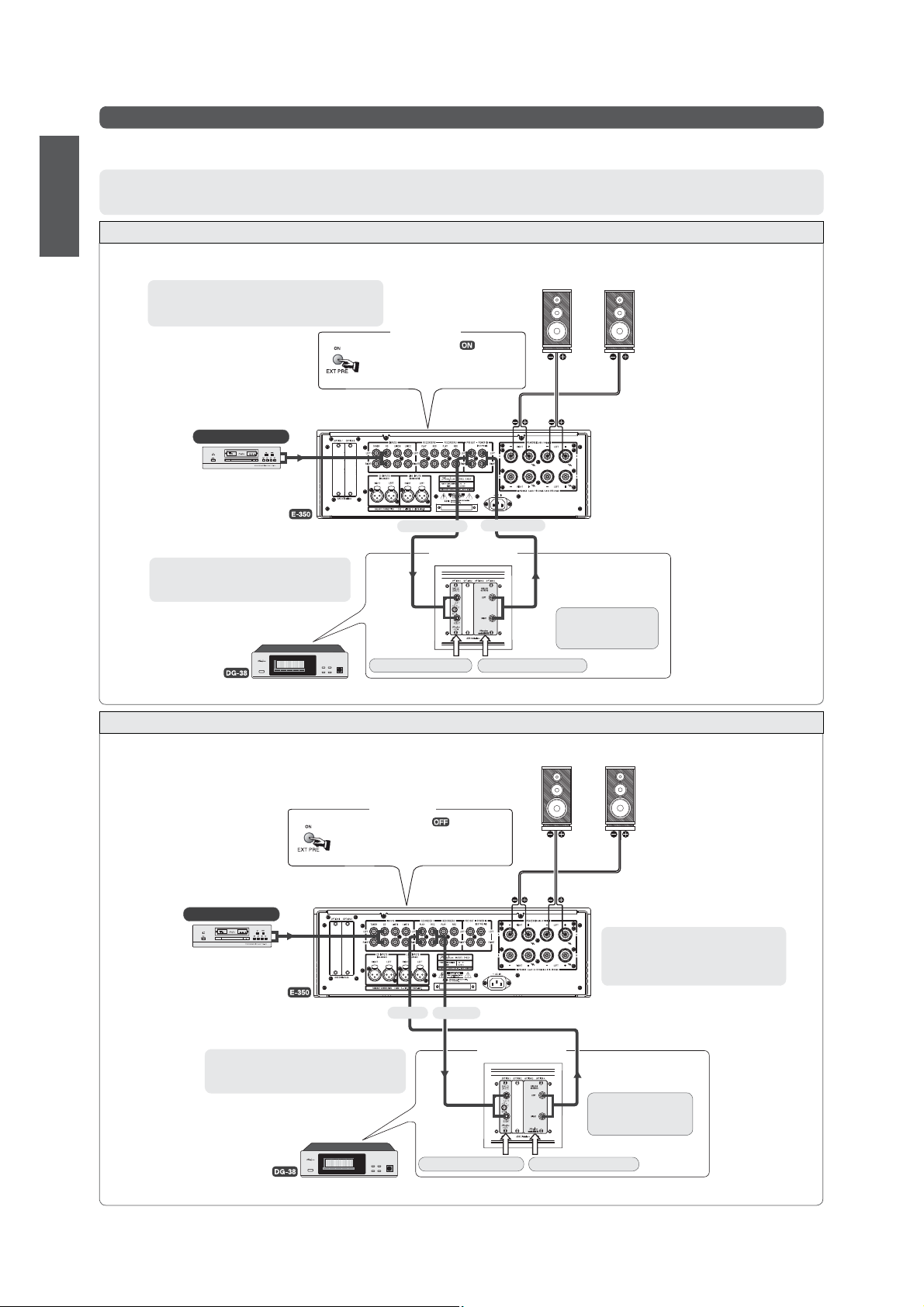
Playback with DG-38/DG-48 connected
The Digital Voicing Equalizer DG-38 or DG-48 can be connected to the E-350, allowing highly precise sound fi eld compensation during playback of program sources.
ENGLISH
● For details on connection and operation of the DG-38/DG-48, please refer to instruction manual of the respective component.
Memo
Both connection examples below show the connection to the DG-38.
When using the DG-48, option boards are not required, because the DG-48 incorporates line inputs and outputs as standard equipment.
Connection example 1
The DG-38/DG-48 is connected between the preamplifi er and power amplifi er sections of the E-350, with the EXT PRE button set to ON to separate the
preamplifi er and power amplifi er sections.
Note:
Do not set the EXT PRE button to OFF. Doing so takes
the DG-38 out of the signal path and may cause a sudden
increase in volume.
✽ Use INPUT SELECTOR of E-350
to select program source.
Source component
CD player
Analog
output
Front panel
Set EXT PRE button to
LED lit)
● Preamplifi er and power amplifi er sections are
separated.
(“EXT PRE”
Left speaker
Right speaker
From PRE OUT
To POWER IN
DG-38 rear panel
Use audio cables with plugs
E-350 PRE OUT Ù AI2-U1
E-350 POWER IN Ù AO2-U1
✽ Select “Analog in-1”
on INPUT SELECTOR
menu of DG-38.
Line input board: AI2-U1 Line output board: AO2-U1
Install AI2-U1 and AO2-U1 in option board slots of DG-38.
✽ Set switch on AI2-U1 board to 96 kHz.
Connection example 2
The DG-38/DG-48 is connected to the RECORDER jacks (RECORDER 1 or RECORDER 2) of the E-350.
Left speaker Right speaker
✽ In the illustration example, RECORDER selector of E-350 is set to “1”.
✽ Use INPUT SELECTOR of E-350 to select the program source.
Front panel
Set EXT PRE button to (“EXT PRE”
LED out)
● Preamplifi er and power amplifi er sections are not
separated.
Source component
CD player
Analog
output
Note:
When the RECORDER selector is set to
“SOURCE” or “REC OFF”, the DG-38 is taken
out of the signal path which may cause a sudden
increase in volume.
From REC
To PLAY
Use audio cables with plugs
E-350 PRE OUT Ù AI2-U1
E-350 POWER IN Ù AO2-U1
DG-38 rear panel
✽ Select “Analog in-1”
on INPUT SELECTOR
menu of DG-38.
Line input board: AI2-U1 Line output board: AO2-U1
Install AI2-U1 and AO2-U1 in option board slots of DG-38.
✽ Set switch on AI2-U1 board to 96 kHz.
8
Page 11
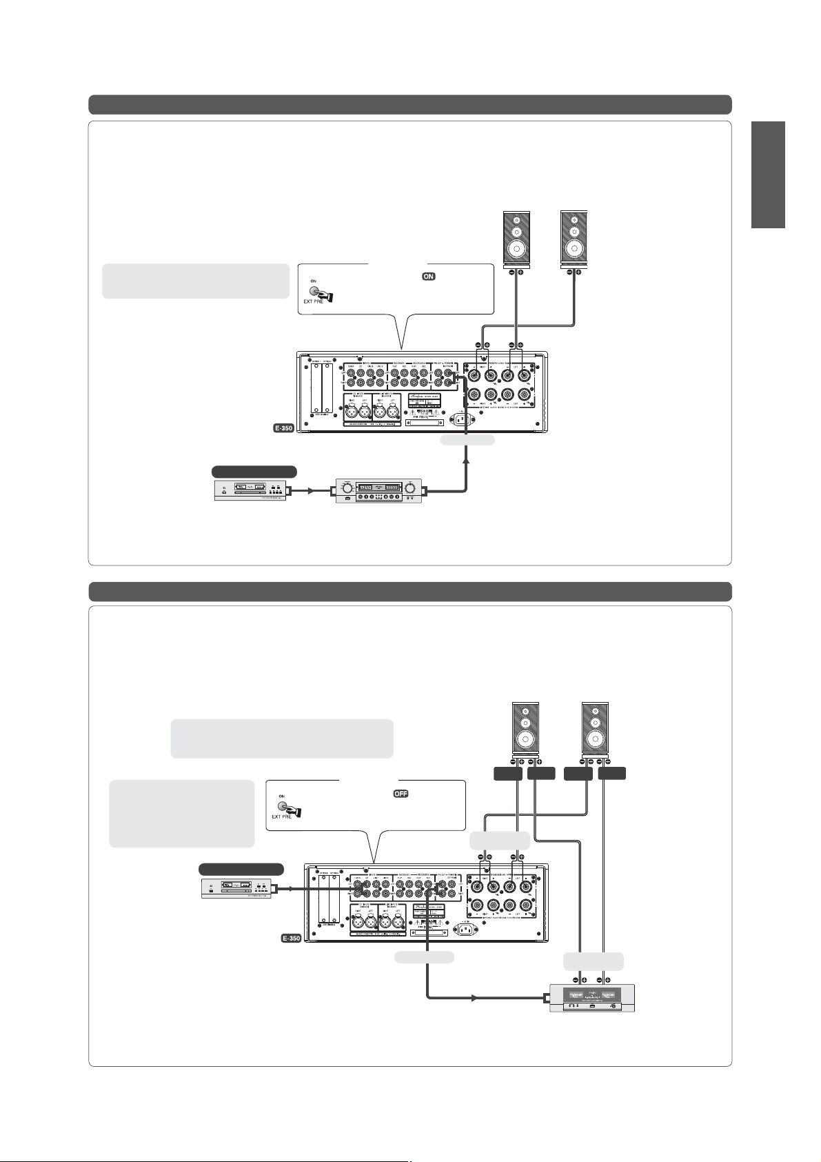
Playback with external preamplifi er
You can set the EXT PRE button to ON to separate the preamplifi er and power amplifi er of the E-350, and use an external
preamplifi er or A/V amplifi er with the power amplifi er of the E-350. An example of such a connection is shown below.
● Connect the output of the external preamplifi er to the POWER IN jacks of the E-350.
● Only the power amplifi er of the E-350 is used in this case. The preamplifi er is inactive. Input
source switching, volume adjustment, and other preamplifi er functions must be performed
at the external equipment.
Left speaker
Right speaker
ENGLISH
Note:
If you set the EXT PRE button to OFF, the E-350 will
operate normally (using the internal preamplifi er).
Front panel
Set EXT PRE button to (“EXT PRE”
LED lit)
● Preamplifi er and power amplifi er sections are
separated.
To POWER IN
Source component
CD player
External preamplifi er
or A/V amplifi er etc.
Preamplifi er output
Audio cable
with plugs
Bi-amping connection example
Bi-amping means to drive the low frequency range and high frequency range of a loudspeaker with separate
amplifi ers, for higher sound quality.
● A loudspeaker with built-in crossover network and separate LOW and HIGH input terminals
is required.
● In addition to the E-350, use one more power amplifi er of similar gain.
All Accuphase power amplifi ers have the same gain (28 dB).
Left speaker Right speaker
Connections for example shown in illustration
E-350 speaker outputs Ù LOW terminals of speaker
Other power amplifi er Ù HIGH terminals of speaker
Note:
Do not set the EXT PRE button to
ON while the power amplifi er is being
used. Otherwise the LOW driver (the
driver connected to the power amplifi er
of the E-350) of the loudspeaker will
be cut off.
Source component
CD player
LOW
terminals
terminals
To HIGH terminals
of speakers
HIGH
HIGH
LOW
terminals
Front panel
Set EXT PRE button to (“EXT PRE”
LED out)
● Preamplifi er and power amplifi er sections are not
separated.
Analog
output
terminals
To LOW terminals
of speakers
From PRE OUT
INPUTS
Audio cable with plugs
Power amplifi er
9
Page 12
Option Boards
ENGLISH
Three types of option boards can be used in the E-350: the Digital Input Board DAC-20, Analog Disc Input Board AD-20, and Line Input Board LINE-10. These boards
can be installed in the two rear-panel slots (OPTION 1 or 2), as required.
● Always turn the power of the E-350 off before inserting or removing any option board.
● Any board can be installed in any of the two slots.
● The Analog Disc Input Board AD-9/AD-10 and the Line Input Board LINE-9 can also be used.
Using Option Boards
Playback of CD or similar with digital input
Install the Digital Input Board DAC-20.
✽ The board can handle digital output signals from a CD player, MD recorder
or other digital component with a sampling frequency of up to 96 kHz. The
connection can be made with coaxial or optical fi ber cable.
Connection cables
COAXIAL: Use a digital coaxial cable with RCA plugs.
OPTICAL: This is a connector for JEITA standard optical fi ber cable.
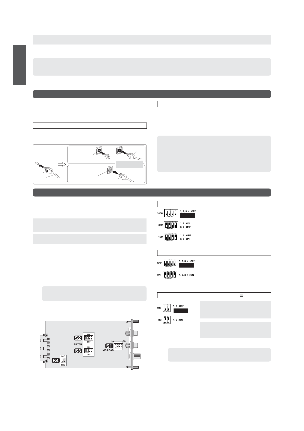
Optical fi ber cable
connection
Remove protective cover
from connector tip
Plug
Optical fi ber
cable
If connector has a
blind plug
Optical connector
Pull out blind plug
If connector has a shutter
Push inwards to
open shutter
Align plug guide with
connector and insert
Plug
Plug
Analog disc (AD) playback
Install the Analog Disc Input Board AD-20.
[When using the AD-10: The setting content is the same, but because the number
and position of DIP switches and the setting procedure are different, be sure to
consult the AD-10 documentation.]
Note:
Always turn the power of the E-350 off before inserting or removing any
option board.
Before inserting the board, the DIP switches (S1 - S3) on the board must
be set to the required positions.
Note: Use a sharp pointed object to move the switch levers and make sure
that the levers are set fully to one side. If a lever is set only half-way,
correct operation will be not be achieved.
A S1: MC LOAD
MC input impedance selector: 10/30/100 ohms
B S2, S3: FILTER
Subsonic fi lter on/off
C S4: MC/MM selection
Memo
In the E-350, the MC/MM button on the front panel has priority. Therefore
there is no need to set the S4 switch on the board.
Playback
A Verify that the VOLUME control is turned fully down and then turn on the
E-350 and the other components. Set the INPUT SELECTOR to the position
for the option board slot in which the DAC-20 is installed (OPTION 1 or 2).
B Set the source component to the play condition and adjust the volume to a
suitable level.
Note:
● Do not connect both the COAXIAL output and the analog outputs (balanced/
unbalanced) of a component to the E-350 at the same time. Otherwise
ground loops may occur which can cause noise.
● When equipment is connected to both the COAXIAL and the OPTICAL
input (of the DAC-20), only one of the signals will be selected. To control
the selection, disconnect the cable for the component that is currently not
playing, or turn power of that component off.
A
S1: MC LOAD – MC input impedance selector (Set on board)
Factory default
setting
B
S2, S3: FILTER – Subsonic fi lter on/off (Set on board)
Factory default
setting
C
S4: MC/MM – Equalizer gain selection (Setting of MC/MM button 5 on panel has priority)
Factory default
setting
As a general guideline, set this switch according to the
rated internal impedance of the MC cartridge.
20 ohms or more: 100 ohm position
Less than 20 ohms: 30 ohm or 10 ohm position
● Generally, the input impedance setting should be
about 2 to 3 times the rated cartridge impedance.
However, since the requirements of some car tridges
may vary, the fi nal setting should be determined by
ear.
● This switch affects both the left and right channels.
This fi lter has a cut-off frequency of 25 Hz and a steep
attenuation slope of –12 dB/octave. It cuts off unwanted
subsonic signal components without affecting the audible
range. Removing subsonic noise components is useful
for example to stop excessive woofer excursions caused
by record warps or turntable rumble, etc.
● Be sure to set both switches to the same position.
MM: For moving magnet cartridges with high
output
Gain: 36 dB
Input impedance: 47 kilohms
10
AD-20 component side (location of switches S1 - S4)
MC: For moving coil cartridges with low output
Gain: 62 dB
Input impedance: As selected with S1
● This switch affects both the left and right channels.
Memo
When installed in the E-350, the DIP switch S4 on the AD-20 board need
not be set.
Page 13
Connection
Connect the output cable from the analog record player correctly to the input
jacks on the board. Also connect the ground cable from the analog record player
to the ground (GND) terminal on the board.
Playback
A Verify that the VOLUME control is turned fully down and then turn on the
E-350 and the other components. Set the INPUT SELECTOR to the position
for the option board slot in which the AD-20 is installed (OPTION 1 or 2).
B Lower the stylus onto the record and adjust the volume to a suitable level.
C If the record is notably warped or if there are excessive woofer excursions
caused by turntable rumble, enabling the subsonic fi lter can help to reduce
noise.
ENGLISH
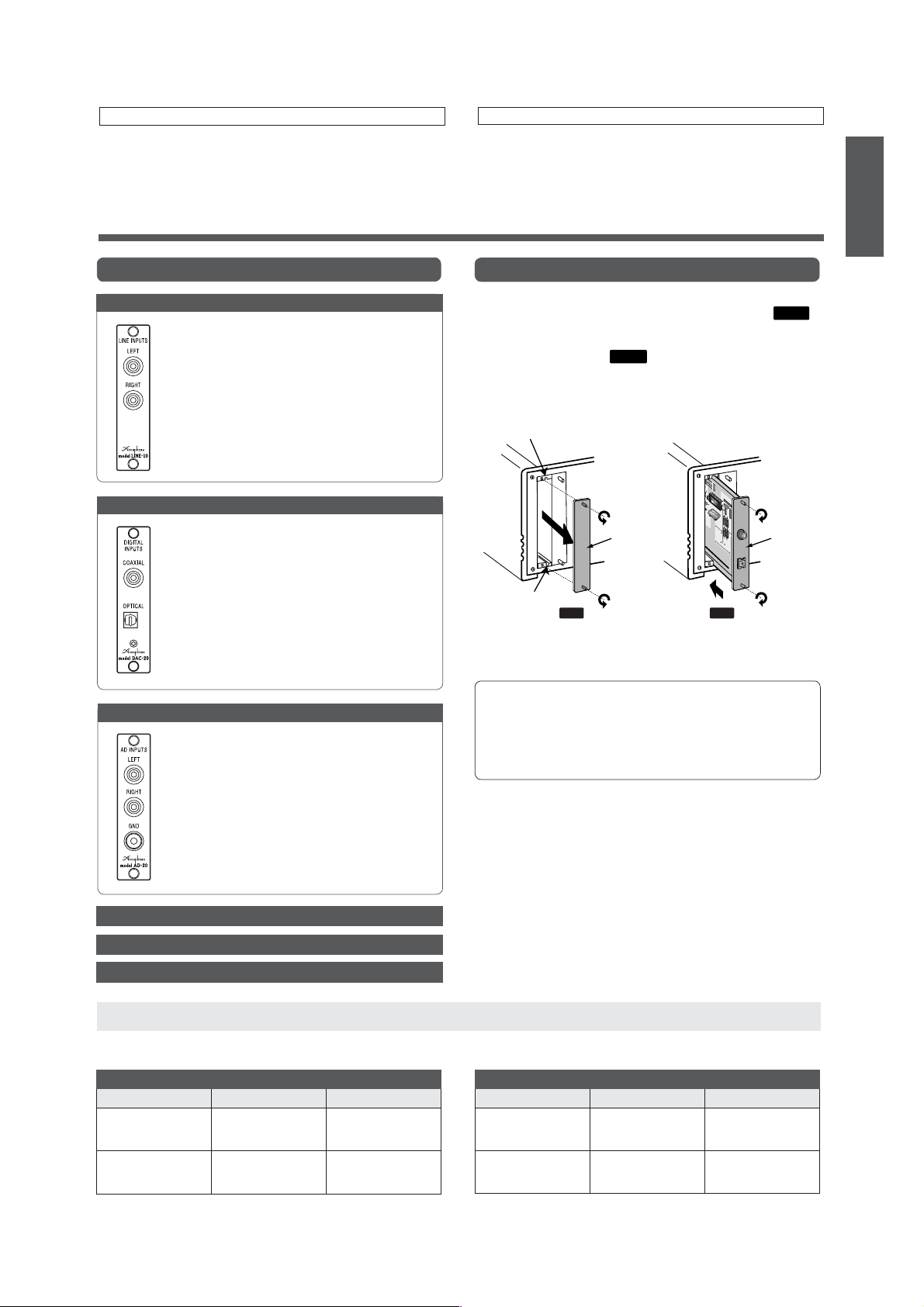
Option Board Types
Line Input Board LINE-10
This option board provides an additional set of analog line
inputs that are similar to the INPUTS of the E-350. They can
be used to connect a CD player, tuner, or other component
with analog output.
Digital Input Board DAC-20
This board provides a coaxial and an optical input for connecting
the digital signal from source components with digital output.
As there is no provision for input switching, select one of the
inputs.
Connection cables
COAXIAL: For digital coaxial cable
OPTICAL: For optical fi ber cable
Guaranteed specifi cations, standards
Input format: JEITA CP-1201 / AES-3 compliant
Sampling frequency:
Digital input: COAXIAL 0.5 Vp-p, 75 ohms
OPTICAL –27 to –15 dBm
Analog Disc Input Board AD-20
This board serves for playback of analog records. It contains a
high-performance, high-gain phono equalizer. The board can
be used with any type of phono cartridge.
● By installing two of these boards, two different phono
cartridges can be connected at the same time.
LEFT, RIGHT analog record player input jacks
Connect the output cable from the analog record player to
these jacks.
GND terminal
Connect the ground cable from the analog record player to
this terminal.
32 – 96 kHz
Option Board Installation
A Set the power switch of the E-350 to OFF.
B
On the rear panel, remove the panel covering the option slot (see
✽Retain the removed sub panel.
C Insert the option board by sliding it into the top and bottom guide rails of
the option board slot
connector, give it a slight push until the board is fi rmly seated. (The board
must be fl ush with the panel.)
D Secure the board with the two screws at the top and bottom.
Guide rail
Guide rail
(see
Fig 1 Fig. 2
)
. When the board touches the internal
Fig. 2
Sub
panel
* The illustration shows the DAC-20.
Fig. 1
Option board
).
RCAUTION
● Be sure to turn the E-350 OFF before inserting or removing any option
board. Otherwise damage to the board or to the amplifi er can occur.
● Take care not to touch the components, the printed circuit side, or the
connector edge of the board, to prevent possible contact problems or
damage. Hold the board only by the edges or the rear panel.
● Be sure to securely fasten the board with the two screws. Otherwise
insuffi cient grounding may lead to function problems and damage.
Analog Disc Input Board AD-10
Analog Line Input Board AI2-U1 (for use in DG-38)
Analog Line Output Board AO2-U1 (for use in DG-38)
Optional Cables
Analog unbalanced cables (with RCA plugs) and balanced cables (with XLR plugs) for audio connections are available as options from Accuphase.
✽ 5 m, 7.5 m, and 10 m cable lengths are also available.
OFC Series: Oxygen-Free Copper Litz Wire
Model number Cable length Plug type
L-10G
L-15G
L-30G
LC-10A
LC-15A
LC-30A
1.0 m (2 cables)
1.5 m (2 cables)
3.0 m (2 cables)
1.0 m (2 cables)
1.5 m (2 cables)
3.0 m (2 cables)
RCA
RCA
RCA
XLR
XLR
XLR
Model number Cable length Plug type
SL-10G
SL-15G
SL-30G
SLC-10
SLC-15
SLC-30
SR Series: 7N Purity Twisted Wire
1.0 m (2 cables)
1.5 m (2 cables)
3.0 m (2 cables)
1.0 m (2 cables)
1.5 m (2 cables)
3.0 m (2 cables)
RCA
RCA
RCA
XLR
XLR
XLR
11
Page 14
Remote Control
ENGLISH
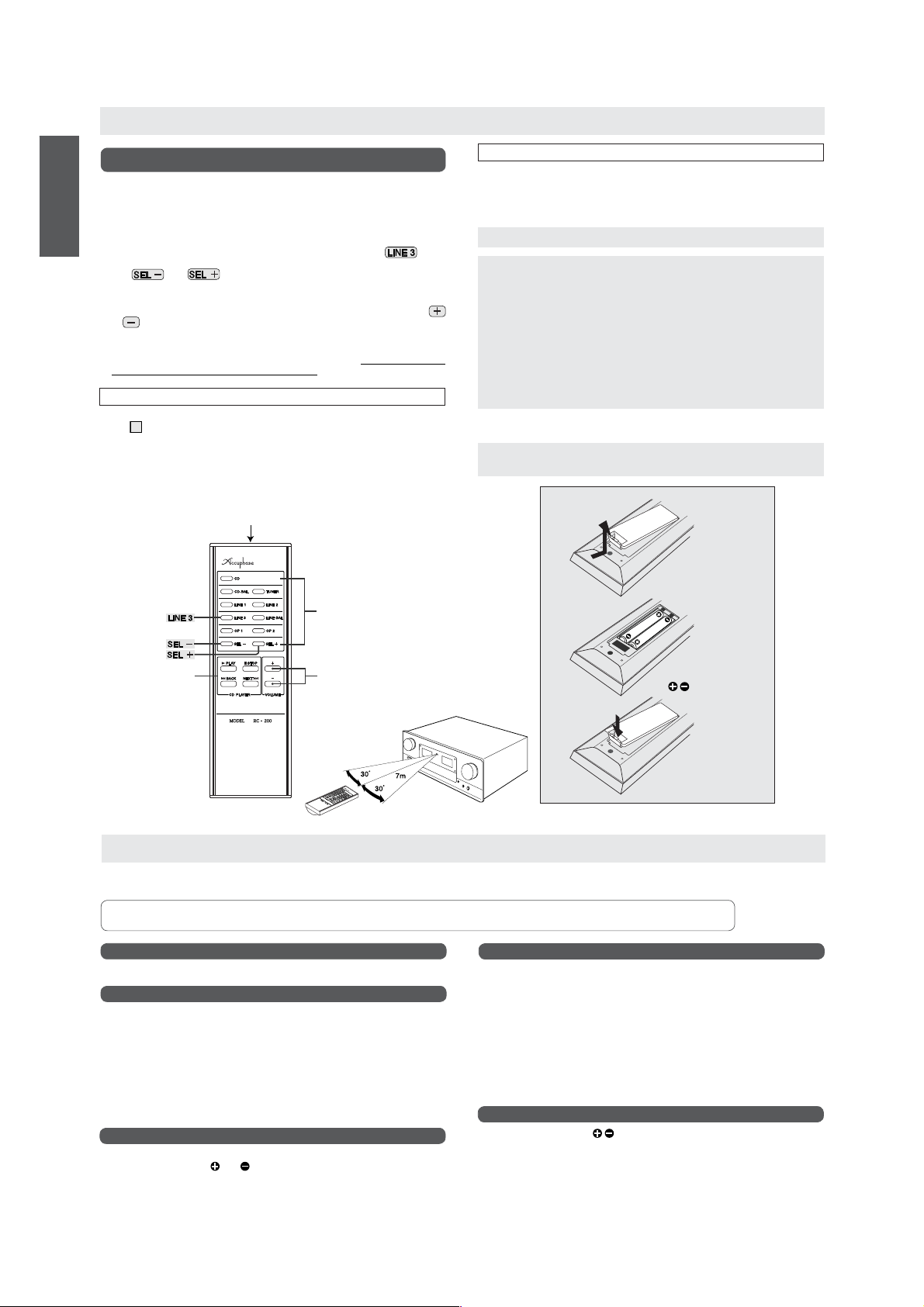
Using the remote commander RC-200
The supplied remote commander RC-200 can be used to operate the E-350 from
anywhere in the room.
A
INPUT SELECTOR buttons
Serve to select program sources connected to the inputs on the rear panel of the
E-350. Simply press a button for the desired program source. The corresponding
LED on the circumference of the INPUT SELECTOR knob of the E-350 lights up.
Because the E-350 does not have a LINE 3 position, pressing the
on the remote commander has no effect.
The
SELECTOR on the E-350 counterclockwise and clockwise.
B
VOLUME buttons
These buttons are linked to the volume control on the unit. Press the VOLUME
or
VOLUME control knob on the E-350 turns accordingly.
3
CD PLAYER – CD player control
These buttons allow operation of an Accuphase CD player. Please note that the
SA-CD/CD transport DP-100 cannot be controlled.
and buttons have the same effect as turning the INPUT
button to increase or decrease the volume. When a button is pressed, the
Operation
To operate the unit, point the transmitter at the tip of the remote commander towards the
on the E-350. The effective operation range is shown in the illustration.
sensor
16
● Take care not to drop the remote commander or spill any liquid on it.
● Do not subject the remote commander to high temperatures or humidity, such as in
locations exposed to direct sunlight or close to heating appliances, etc.
Transmitter
(point at sensor on E-350)
A INPUT
(No effect)
SELECTOR
button
About Batteries
■ Battery replacement
The batteries will last for about 8 months with normal use. When you notice that
the effective range of the remote commander decreases, you should replace the
batteries. When the batteries are totally exhausted, pressing any of the buttons will
have no effect.
The battery type is IEC R03 (size AAA). Always replace both batteries together.
RCAUTION
Observe the following precautions to prevent battery leakage or damage.
● Insert the batteries with correct polarity, as marked inside the case.
● Do not use a mixture of old and new batteries together.
● Use only the specifi ed battery type, and do not mix different battery types.
● Remove the batteries if the remote commander will not be used for a long
time.
● If battery leakage has occurred, contact an Accuphase Service Station. If battery
fl uid has come into contact with your body, wash the affected part with plenty of
water.
RWARNING
Never try to charge regular dry cell batteries not designed for recharging. Otherwise
there is a risk of explosion, leakage, fi re, and injury.
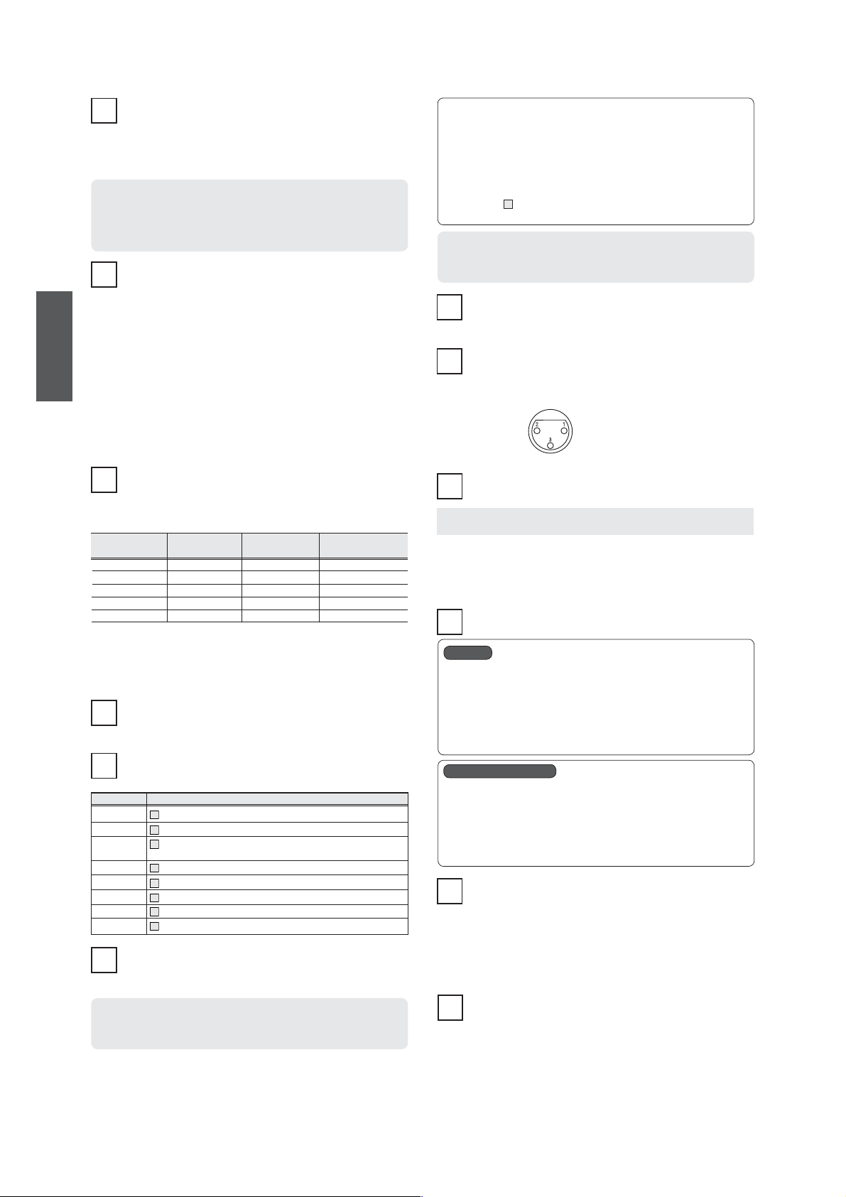
Replacing the Batteries
Push the tab in the
arrow direction to open
the battery case.
C CD PLAYER buttons
for operation of an
Accuphase CD player
(except DP-100)
B VOLUME
control buttons
Insert two IEC R03 (size
AAA) batteries with correct
polarity.
Push the lid down until it
snaps into place.
Troubleshooting
If there seems to be a problem with the unit, please check the following points fi rst. If the problem persists, contact an Accuphase Service Station or your
Accuphase dealer.
RCAUTION
No power
● Is the power cord plugged in correctly?
No sound
● Are the program source components turned on?
● Check the setting of the speaker selector.
... When set to OFF, no sound will be heard.
● Check the setting of the EXT PRE button.
... When set to ON, the preamplifi er and power amplifi er sections are separated,
and no sound will be heard if no component is connected to the POWER IN
jacks.
● Are all components and the loudspeakers connected correctly?
● Is the input selector set to the correct position?
● Is the recorder selector set to the correct position?
Remote commander does not operate
● Check whether batteries are inserted.
● Check whether battery
● Replace the batteries with fresh ones.
● Remove any obstacles between the commander and the unit.
Before changing any connections, be sure to turn the power to all components OFF.
No sound in one channel
● Are all components and the loudspeakers connected correctly?
● Is the balance control set correctly?
● Try reversing the left and right speaker cables.
Still no sound in the same channel:
... Check the cables and the loudspeaker itself.
No sound in the other channel:
... E-350 or source component may be defective.
● Try reversing the left and right input cables.
Still no sound in the same channel:
... E-350 may be defective.
No sound in the other channel:
... Cables or source component may be defective.
Stereo image is fuzzy
● Check whether speaker
and polarity is correct.
polarity is not reversed in one channel.
12
Page 15

Pièces et fonctions
POWER – Interrupteur d’alimentation
Enfoncer cet interrupteur pour allumer l’amplificateur. Appuyer à
1
nouveau sur l’interrupteur pour l’éteindre. Pendant un inter valle d’environ
5 secondes après la mise sous tension, aucun son n’est émis des
enceintes, à cause de l’activation du circuit de sourdine.
● Après avoir éteint l’appareil, ne pas le rallumer immédiatement (attendre au
moins 10 secondes).
SPEAKER – Sélecteur d’enceinte
Sert à sélectionner deux paires d’enceintes connectées aux bornes
2
d’enceinte “A” et “B”.
OFF
Les deux paires d’enceintes sont désactivées, par exemple pour l’écoute par
casque.
A, B
La paire d’enceinte respective est activée.
A + B
Deux paires d’enceintes sont entraînées simultanément. Dans ce cas, utiliser
des enceintes ayant une impédance nominale de 4 ohms ou plus, car les deux
paires sont connectées en parallèle.
Cette position est également utilisée pour le bi-câblage d’une simple paire
d’enceintes (utilisant des câbles séparés pour les gammes de fréquences
basses et pour les fréquences moyennes/hautes).
COPY – Sélecteur de copie
Lorsque deux enregistreurs sont connectés au E-350, la copie peut être
3
effectuée dans chaque direction à l’aide de ce sélecteur.
1 2, 2 1
Pour utiliser l’enregistreur connecté aux prises RECORDER 1 du panneau
arrière comme source et l’enregistreur connecté aux prises RECORDER 2
comme enregistreur, régler le sélecteur sur “1 2”. Pour copier dans la direction
opposée, utiliser la position “2 1” .
OFF
Régler le sélecteur sur cette position lorsque la copie n’est pas souhaitée.
RECORDER – Sélecteur d’enregistreur
4
REC OFF
Sélectionner cette position en fonctionnement normal (sans enregistrement).
L’amplifi cateur reproduit la source de programme sélectionnée, mais le signal
n’apparaît pas sur les sorties REC.
– Voyant “REC ON” allumé
SOURCE
Sélectionner cette position lorsqu’on veut enregistrer. L’amplifi cateur reproduit la
source de programme sélectionnée, et le signal apparaît sur les sorties REC.
– Voyants “RECORDER” et “REC ON” allumés
1, 2
Sélectionner pour reproduire le signal à partir d’un enregistreur.
Sélectionner la position selon l’entrée “PLAY” du panneau arrière (RECORDER
1 ou RECORDER 2) utilisée.
MC/MM – Sélecteur MC/MM
5
Cette fonction est disponible uniquement lorsque la carte d’entrée du
disque analogique AD-20 est installé
Ce sélecteur détermine le gain phono pour la lecture de disques
analogiques (disques phono) avec la AD-20.
● Touche enfoncée (MC) : Voyant “MC” allumé
● Touche enfoncée de nouveau (MM) : Voyant “MC” éteint
MC
Cette position doit être utilisée pour des cellules à bobine mobile (MC) avec
une sortie basse. Régler l’impédance d’entrée à l’aide des commutateurs DIP
de la carte.
MM
Cette position doit être utilisée pour des cellules à aimant mobile (MM).
L’impédance d’entrée est de 47 kohms.
Remarque :
● La commutation MC/MM est disponible lorsque INPUT SELECTOR
réglée sur la position correspondant à la fente de la carte optionnelle dans
laquelle la AD-20 est installée.
Pour la commutation MC/MM, le réglage du sélecteur MC/MM 5 a la priorité.
●
La AD-20 a des réglages de commutateur DIP pour la sélection MC/MM,
mais les réglages de la carte sont remplacés par le sélecteur du E-350.
●
Les réglages MC LOAD et FILTER sont effectués uniquement sur la carte
AD-20. Il n’y a pas de provisions pour le réglage de ces éléments sur le
E-350.
● La carte d’entrée analogique AD-9 ou AD-10 peut également être utilisée,
mais dans ce cas, la sélection MC/MM peut être effectuée uniquement sur
la carte. Le réglage du sélecteur MC/MM du E-350 n’a pas d’effet.
EXT PRE – Touche de séparation préamplificateur/
6
amplifi cateur de puissance
Cette touche permet d’utiliser séparément les sections préamplifi cateur
et amplifi cateur de puissance du E-350.
est
14
● Touche enfoncée (ON) : Voyant “EXT PRE” s’allume
Préamplifi cateur et amplifi cateur de puissance sont séparés.
● Touche enfoncée de nouveau (OFF) : Voyant “EXT PRE” s’éteint
Fonctionnement normal, préamplifi cateur et amplifi cateur de puissance
non séparés.
Remarque :
Ne pas utiliser l’interrupteur pendant la lecture. Toujours réduire le volume au
minimum avant de mettre l’interrupteur en position ON ou OFF.
MONO – Sélecteur de mode mono/stéréo
Ce commutateur permet de sélectionner le fonctionnement stéréo ou
7
mono. Lorsque le commutateur est enfoncé, les deux canaux sont
combinés et le même signal est envoyé aux enceintes gauche et droite.
Si la position d’écoute est approximativement à distance égale des enceintes,
l’image sonore devrait être centrée.
Touche enfoncée (fonctionnement monophonique) : Voyant “MONO” allumé
●
● Touche enfoncée de nouveau (fonctionnement stéréo) : Voyant “MONO” éteint
Remarque :
Lorsque le réglage du sélecteur RECORDER est commuté à “SOURCE”,
le réglage monophonique est annulé automatiquement. Pour enregistrer en
mode mono, appuyer de nouveau sur la touche MONO après l’utilisation du
sélecteur RECORDER.
METER – Touche allumage/extinction de l’affi chage du
8
crête-mètre
● Touche enfoncée (OFF) :
Les voyants du crête-mètre sont éteints et les crête-mètres ne fonctionnent pas.
● Touche enfoncée de nouveau (ON) :
Les voyants du crête-mètre s’allument et les crête-mètres fonctionnent.
COMP – Touche de compensation physiologique
Cette touche sert à restaurer l’équilibre de tonalité naturelle à des niveaux
9
d’écoute faibles. L’oreille humaine devient moins sensible aux fréquences
extrêmes car la compensation physiologique diminue. Cela crée souvent une
perception du son comme faible ou défi cient, en particulier dans la gamme des
basses fréquences. La touche COMP compense cet effet en accentuant la gamme
inférieure (+6 dB à 100 Hz).
● Touche enfoncée (ON) : Voyant “COMP” allumé
● Touche enfoncée de nouveau (OFF) : Voyant “COMP” éteint
TONE, (BASS, TREBLE ) – Commandes de tonalité
10
TONE – Touche de commande de tonalité activée/désactivée
● Touche enfoncée (ON) : Voyant “TONE” allumé
● Touche enfoncée de nouveau (OFF) : Voyant “TONE” éteint
✽ Lorsque la touche est placée en position ON, les commandes BASS et
TREBLE peuvent être utilisée.
✽ Lorsque la touche est réglée sur OFF, l’ensemble de la circuiterie de
contrôle des tonalités sera court-circuitée.
– Commande des graves
BASS
Lorsque cette commande est tournée vers la droite à partir de cette position
centrale (0), la gamme des basses fréquences est accentuée et lorsque
cette commande est tournée vers la gauche, les basses fréquences sont
atténuées.
● Fréquence de retournement : 300 Hz
● Plage de réglage : ±10 dB à 50 Hz
TREBLE
– Commande des aiguës
Lorsque cette commande est tournée vers la droite à partir de la position
centrale (0), la gamme des hautes fréquences est accentuée et lorsque
cette commande est tournée vers la gauche, les hautes fréquences sont
atténuées.
● Fréquence de retournement : 3 kHz
● Plage de réglage : ±10 dB à 20 kHz
BALANCE – Commande d’équilibre
11
Cette commande sert à régler l’équilibre stéréo gauche/droite.
● Normalement, la commande doit être en position centrale (0).
ATTENUATOR – Touche d’atténuateur
12
Chaque pression sur la touche ATTENUATOR permet de réduire le niveau
sonore d’un dixième (ce qui équivaut à une atténuation de -20 dB).
● Touche enfoncée (ON) :
● Touche enfoncée de nouveau (OFF) : Voyant “ATTENUATOR” éteint
Voyant “ATTENUATOR” allumé
13
FRANÇAIS
Page 16
PHONES – Prise casque
Un casque stéréo peut être branché à cette prise.
13
✽ Lorsqu’on veut utiliser seulement le casque, placer le commutateur SPEAKERS
en position OFF.
✽ Régler le niveau d’écoute à l’aide de la commande de volume global.
✽ Utiliser un casque d’une impédance comprise entre 8 et 100 ohms.
Remarque :
Si les sections préamplificateur et amplificateur de puissance ont été
séparées par le réglage de la touche EXT PRE en position ON, la prise
casque de l’appareil transportera le signal de la section de l’amplifi cateur de
puissance du E-350. Le volume devra par conséquent être ajusté au niveau
du préamplifi cateur externe.
INPUT SELECTOR – Sélecteur d’entrée
Sert à sélectionner les différentes sources de programme connectées
14
aux entrées du panneau arrière. Les touches correspondantes de la
FRANÇAIS
télécommande RC-200 peuvent également être utilisées.
TUNER, CD, LINE 1, 2
Sert à sélectionner les différents composants connectés aux entrées
dissymétriques classiques (avec câble audio à fi ches dissymétriques) du
panneau arrière.
CD-BAL, LINE-BAL
Sert à sélectionner les différents composants connectés aux entrées
symétriques (avec câble audio à fi ches symétriques) du panneau arrière.
OPTION 1, 2
Sélectionner les composants connectés aux cartes optionnelles installées dans
les fentes OPTION 1 et OPTION 2 du panneau arrière.
● Pour des informations sur les cartes optionnelles, voir “Cartes optionnelles”.
✽ Le sélecteur INPUT SELECTOR n’a pas de cran d’arrêt ou de butée (il peut
être tourné en continu).
Crête-mètre
L’échelle du crête-mètre indique le niveau de sortie en dB (décibels) et
15
est également calibrée en watts sous une charge de 8 ohms. Sous une
charge de 4 ohms, les chiffres doivent être doublés, et sous une charge
de 16 ohms, ils doivent être réduits de moitié. Les niveaux de sor tie avec un signal
d’onde sinusoïdale pour les différentes charges sont indiqués ci-dessous.
Indication de sortie
(dB/%)
0 dB: 100 % 200 W 100 W 50 W
–10 dB : 10 % 20 W 10 W 5 W
–20 dB : 1 % 2 W 1 W 500 mW
–30 dB : 0,1 % 200 mW 100 mW 50 mW
–40 dB : 0,01 % 20 mW 10 mW 5 mW
Les crête-mètres sont des conceptions à lecture de crête, qui permettent de suivre
avec précision les variation rapides d’amplitude et de fréquence des signaux
musicaux. Afi n de faciliter la lecture, le temps de retard des crête-mètres est
réglé à une valeur inférieure au temps de montée. Si la source de programme
contient du bruit ou une grande quantité de transitoires, l’indication du crête-mètre
et l’impression de volume auditif pourraient être légèrement différentes.
Détecteur de télécommande
Les signaux infrarouges de la télécommande RC-200 fournie sont
16
reçus par ce détecteur. Lors de l’utilisation de la télécommande, pointer
l’émetteur dans la direction de ce détecteur.
Section d’affi chage
Cet état de fonctionnement des différentes touches et commandes est
17
affi ché par l’état des voyants allumés/éteints sur ce panneau.
Voyant allumé
RECORDER
REC ON Sélecteur RECORDER : SOURCE 1, 2 (L’enregistrement est possible)
EXT PRE
(Le préamplifi cateur/amplifi cateur de puissance sont séparés)
MC Touche MC/MM : MC
MONO Touche MONO : ON (Le mode mono est sélectionné)
COMP Touche COMP : ON (La compensation physiologique est sélectionnée)
TONE BASS, TREBLE : Les commandes de tonalité sont actives
ATTENUATOR
18
Remarque :
Lors du changement du réglage de la touche EXT PRE, au cours d’un
changement de sources de programme, et lors de la mise sous et hors tension,
la commande de volume doit toujours être tournée au minimum.
Etat de fonctionnement
Touche EXT PRE : ON
Touche ATTENUATOR : ON (La fonction d’atténuation est activée)
VOLUME – Commande de volume
Le fait de tourner cette commande dans le sens des aiguilles d’une montre
augmente le niveau d’écoute. La commande peut également être utilisée
avec la télécommande RC-200.
de 4 ohms de 8 ohms de 16 ohms
Sélecteur RECORDER : 1, 2 (L’enregistreur est en cours de lecture)
4
4
6
5
7
9
10
12
Le E-350 est équipé d’une commande de volume innovatrice appelée
AAVA-II (Accuphase Analog Vari-gain Amplifi er-II) (amplifi cateur de gain varianalogique Accuphase). Le principe de fonctionnement de cette commande
est totalement différent de celui des commandes conventionnelles utilisant des
résistances. Avec le AAVA-II, le signal musical est pondéré en 16 étapes, et
un circuit de commutation de courant sert à sélectionner le signal, modifi ant
ainsi le volume.
En fonctionnement effectif, un VR rotatif conventionnel est utilisé. Lorsque la
commande de
de réglage, et les 16 commutateurs de courant sont réglés sur ON ou OFF.
Remarque :
Lorsque des enceintes à haut rendement sont utilisées, un son émis par le
fonctionnement du commutateur de courant pourra être entendu lorsque la
commande de VOLUME est tournée. Ceci ne signifi e pas une défaillance.
INPUTS : TUNER, CD, LINE 1, LINE 2 – Entrées de niveau
19
de ligne
Ces entrées sont des prises d’entrée de ligne asymétriques
conventionnelles.
CD/LINE INPUTS (BALANCED) – Entrées symétriques
Ce sont des entrées pour une connexion symétrique qui élimine le
20
bruit externe induit. Les entrées acceptent le signal de n’importe quel
composant équipé de sorties symétriques, tel qu’un lecteur de CD ou
un tuner.
A : Masse
B : Inversé (–)
C : Non-inversé (+)
● Des câbles audio symétriques sont disponibles auprès de Accuphase.
RECORDER 1, 2 – Prises d’entrée/sortie de l’enregistreur
21
Ces prises servent à la connexion de deux enregistreurs.
Prises PLAY Ù Prises LINE OUT de l’enregistreur
Prises REC Ù Prises LINE IN de l’enregistreur
✽ Le signal de sortie aux prises REC n’est pas affecté par les commandes de
volume, de commande de tonalité, et les paramètres du compensateur de
l’amplifi cateur.
✽ Garder à l’esprit que, lorsque le commutateur MODE est placé en position
“MONO”, la sortie d’enregistrement sera monophonique.
Prises PRE OUT/POWER IN (EXT PRE IN)
22
PRE OUT
Ces prises permettent d’utiliser séparément la section préamplifi cateur.
● Le signal sur ces prises est toujours émis, indépendamment du réglage
de la touche EXT PRE.
● Les sorties peuvent être utilisées pour connecter un second amplifi cateur
de puissance pour la bi-amplifi cation.
La bi-amplification utilise des amplificateurs de puissance séparés pour la gamme
✽
basses fréquences et pour la gamme moyennes/hautes fréquences.
POWER IN (EXT PRE IN)
Ces prises permettent d’utiliser séparément la section de l’amplifi cateur
de puissance.
● Lorsque la touche EXT PRE a été réglée sur “ON” pour la séparation du
préamplifi cateur et de l’amplifi cateur de puissance du E-350, ces prises
servent de prises d’entrée d’amplifi cateur. La commutation de la source
d’entrée, le réglage de volume et les autres fonctions du préamplifi cateur
doivent être effectués sur l’équipement externe.
Bornes SPEAKERS (A, B)
Deux paires d’enceintes peuvent être connectées aux bornes A et B.
23
✽ Utiliser des enceintes ayant une impédance nominale de 4 à 16 ohms.
✽ Si deux paires d’enceintes sont entraînées simultanément, utiliser des
enceintes ayant une impédance nominale de 8 à 16 ohms.
✽ Pour une disposition bi-câblée, connecter les bornes d’entrée A et B
séparément aux câbles pour les gammes de fréquences basses et pour les
fréquences moyennes/hautes.
Entrée secteur
Insérer le cordon d’alimentation fourni dans ce connecteur et brancher
24
l’autre extrémité dans une prise secteur.
Qu’est-ce que c’est AAVA-II ?
18
VOLUME est tournée, sa position est détectée par le circuit
14
Page 17

RAVERTISSEMENT
● Ne pas utiliser l’appareil avec un cordon autre que le cordon d’alimentation
fourni.
● La forme de la prise secteur et de la fi che du cordon d’alimentation
fourni dépendent du pays de destination de l’appareil. Le fait d’utiliser
un autre type de câble que le cordon d’alimentation fourni crée un risque
d’incendie et de dommage.
● Ce produit est disponible dans les versions d’alimentation secteur de
120/230 V CA. S’assurer que la tension indiquée sur le panneau arrière
est identique à la tension de secteur CA de votre région.
Fonctionnement
● Ouvrir l’appareil peut provoquer une électrocution.
● Si l’appareil ne fonctionne pas, il se peut que le fusible interne ait sauté.
Ne jamais essayer de changer le fusible soi-même. Toujours contacter
le revendeur Accuphase ou un centre de service après-vente agréé.
R ATTENTION
● Avant de faire les connexions, s’assurer de mettre le E-350 et tous les autres composants hors tension. En particulier lors du branchement
ou débranchement d’un câble aux prises POWER IN, le E-350 doit être éteint.
● Ne pas utiliser la touche EXT PRE pendant la lecture. Toujours réduire le volume au minimum avant de mettre le commutateur en position
ON ou OFF.
Avant de commencer à utiliser cet appareil, régler les commandes comme ceci.
● VOLUME :
● SPEAKER : Réglé en position pour la paire d’enceinte désirée
● RECORDER : REC OFF (Voyant éteint)
● COPY : OFF
● MC/MM, MONO, COMP, EXT PRE, ATTENUATOR : OFF (Voyants éteints)
● BALANCE : En position centrale
Tourné au minimum (dans le sens contraire des aiguilles d’une montre)
Ecouter un lecteur de CD (via sortie analogique)
Connecter la sortie analogique du lecteur de CD aux prises d’entrée CD (ou
TUNER ou LINE) du panneau arrière. Si le lecteur de CD est équipé de sorties
symétriques, il est recommandé d’utiliser des câbles symétriques et de les
connecter aux connecteurs symétriques CD/LINE INPUTS.
Pour utiliser le mode lecture, suivre les étapes ci-dessous.
A Confi rmer que la commande de VOLUME est tournée au minimum. Puis,
allumer le lecteur de CD et l’amplifi cateur.
B Utiliser le sélecteur INPUT SELECTOR pour sélectionner la position “CD”.
C Faire fonctionner le lecteur de CD et ajuster le niveau d’écoute désiré à l’aide
de la commande VOLUME.
D Si ce réglage est souhaité, régler la touche MONO sur ON (fonctionnement
monophonique) et vérifi er que le son est centré entre les deux enceintes, ainsi
que vérifi er l’action de la commande de tonalité, du compensateur de volume,
et de l’atténuateur.
Ecoute des émissions radio
Connecter la sortie du tuner aux prises d’entrée TUNER (ou CD ou LINE) du
panneau arrière. Si le tuner est équipé de sorties symétriques, il est conseillé
d’utiliser des câbles symétriques et de les connecter aux LINE INPUTS
symétriques.
Placer le INPUT SELECTOR à la position requise et effectuer les mêmes étapes
que celles décrites pour la lecture de CD. Après avoir réglé la station désirée,
ajuster le niveau d’écoute à l’aide de la commande VOLUME.
Enregistrement et lecture avec un enregisteur
Confi rmer que les entrées et sorties de l’enregistreur sont connectées correctement aux prises RECORDER 1 ou RECORDER 2 du panneau arrière du E-350.
Prises REC Ù Prises LINE IN de l’enregistreur
Prises PLAY Ù Prises LINE OUT de l’enregistreur
Lecture
Placer le sélecteur RECORDER sur “1” (ou “2”) et régler l’enregistreur en mode
de lecture. Le son sera entendu via le E-350.
✽ Pour la lecture uniquement, un enregistreur peut également être connecté à
n’importe quelle autre entrée de ligne du E-350.
Enregistrement
Pour l’enregistrement, effectuer les étapes suivantes.
A Sélectionner la source de programme désirée à l’aide du INPUT SELECTOR
et vérifi er qu’elle est bien reproduite par les enceintes.
B Placer le sélecteur RECORDER sur “SOURCE”. Le signal de la source de
programme désirée est maintenant alimenté aux sorties d’enregistrement de
l’amplifi cateur.
C Démarrer l’enregistreur. Le son reproduit par les enceintes est enregistré par
l’enregistreur.
D Les commandes de volume, de l’atténuateur, de la tonalité ou du compensateur
de l’amplificateur n’affectent pas la sortie d’enregistrement. Le volume
peut par conséquent être complètement rabaissé si nécessaire. Le niveau
d’enregistrement doit être changé à l’aide des commandes d’entrée sur
l’enregistreur.
E En réglant le sélecteur RECORDER sur “1” (ou “2”), le son enregistré peut
être contrôlé (lors de l’utilisation d’un enregistreur équipé de trois têtes).
F Etant donné que le même signal est envoyé des prises RECORDER 1 et
RECORDER 2, l’enregistrement peut également être effectué sur deux
enregistreurs simultanément.
Remarque :
Lorsque le réglage du sélecteur RECORDER est commuté à “SOURCE”,
le réglage monophonique est annulé automatiquement. Pour enregistrer en
mode mono, appuyer de nouveau sur la touche MONO après l’utilisation du
sélecteur RECORDER.
Copie
Parce que le E-350 est équipé d’un sélecteur COPY, la copie entre deux
enregistreurs peut être effectuée, indépendamment de la source de programme
reproduite. Toutefois, la copie n’est pas possible lorsque le E-350 est éteint.
Pour effectuer la copie, exécuter les étapes suivantes.
A Pour copier de RECORDER 1 sur RECORDER 2, placer le sélecteur COPY
en position “1 2”. Pour copier dans la direction opposée, utiliser la position
“2 1” .
B Régler l’enregistreur source en mode de lecture et l’enregistreur cible en mode
d’enregistrement.
C Si la copie est effectuée dans le sens “1 2” , le fait de régler le sélecteur
RECORDER sur “RECORDER 1” reproduit le son de lecture de l’enregistreur
source. Le fait de régler le sélecteur sur “RECORDER 2” permet de contrôler
le son enregistré. Pendant la copie dans le sens “2 1”, le phénomène inverse
se produit.
Enregistrement de tuner lorsque l’appareil est éteint
Pendant que l’amplifi cateur est éteint, le signal des entrées TUNER est toujours
connecté aux sorties RECORDER REC, indépendamment des réglages des
sélecteurs INPUT SELECTOR et RECORDER et COPY. Il est par conséquent
possible d’effectuer des enregistrements de la source connectée aux entrées
du tuner sans que votre présence soit nécessaire, à l’aide de la minuterie, sans
même allumer l’amplifi cateur.
Remarque :
Ne jamais allumer l’E-350 alors qu’un enregistrement sans présence est en
cours (et que l’E-350 soit éteint). Si la position de l’entrée du E-350 n’a pas
été confi gurée au préalable sur TUNER, l’enregistrement sera immédiatement
coupé dès la mise en marche de l’appareil. S’assurer à chaque fois qu’aucun
enregistrement sans présence ne soit en marche.
FRANÇAIS
15
Page 18

Lecture avec le DG-38/DG-48 connecté
L’égaliseur numérique DG-38 ou DG-48 peut être connecté au E-350, permettant d’obtenir une compensation très précise du champ sonore pendant la lecture de
sources de programme.
● Pour les détails sur la connexion et sur le fonctionnement du DG-38/DG-48, se référer au mode d’emploi du composant concerné.
Mémo
Les deux fi gures donnent des exemples de connexion possibles du DG-38.
Lorsqu’un DG-48 est utilisé, aucune carte en option n’est nécessaire, car le DG-48 dispose d’entrées et de sorties dans sa version standard.
Exemple de connexion 1
DG-38/DG-48 est connecté entre les sections préamplifi cateur et amplifi cateur de puissance du E-350, à l’aide de la touche EXT PRE placée en position
ON pour séparer les sections préamplifi cateur et amplifi cateur de puissance.
Enceinte droite
FRANÇAIS
Remarque :
Ne pas placer la touche EXT PRE en position OFF. A défaut
d’une telle précaution le DG-38 sort du chemin du signal et
pourrait augmenter brusquement le volume.
✽ Utiliser le sélecteur INPUT SELECTOR
du E-350 pour sélectionner une source
de programme.
Composant source
Lecteur de CD
Sortie
analogique
Panneau avant
Placer la touche EXT PRE en
position (Voyant “EXT PRE” allumé)
● Les sections préamplifi cateur et l’amplifi cateur
de puissance sont séparées.
Enceinte gauche
Vers POWER IN
du DG-38
Carte de sortie de ligne : AO2-U1
Utiliser des câbles audio avec des fi ches
E-350 PRE OUT Ù AI2-U1
E-350 POWER IN Ù AO2-U1
A partir de PRE OUT
Panneau arrière
Carte d’entrée de ligne : AI2-U1
Installer AI2-U1 et AO2-U1 dans les fentes de carte optionnelle du DG-38.
✽ Placer le commutateur de la carte AI2-U1 sur 96 kHz.
Exemple de connexion 2
DG-38/DG-48 est connecté aux prises RECORDER (RECORDER 1 ou RECORDER 2) du E-350.
✽ Dans l’illustration indiquée, le sélecteur RECORDER du E-350 est placé
en position “1”.
✽ Utiliser le sélecteur INPUT SELECTOR du E-350 pour sélectionner une
source de programme.
Panneau avant
Placer la touche EXT PRE en position
(Voyant “EXT PRE” éteint)
● Les sections préamplifi cateur et l’amplifi cateur de
puissance ne sont pas séparées.
Composant source
Lecteur de CD
Sortie
analogique
Enceinte gauche Enceinte droite
✽
Sélectionner “Analog
in-1” dans le menu INPUT
SELECTOR du DG-38
Remarque :
Lorsque le sélecteur RECORDER est placé en
position “SOURCE” ou “REC OFF”, le DG-38
sort du chemin du signal et le volume risque
d’augmenter brusquement.
.
16
Vers PLAY
Utiliser des câbles audio avec des fi ches
E-350 PRE OUT Ù AI2-U1
E-350 POWER IN Ù AO2-U1
A partir de REC
Panneau arrière
du DG-38
✽ Sélectionner “Analog in-
1” dans le menu INPUT
SELECTOR du DG-38.
Carte d’entrée de igne : AI2-U1
Installer AI2-U1 et AO2-U1 dans les fentes de carte optionnelle du DG-38.
✽ Placer le commutateur de la carte AI2-U1 sur 96 kHz.
Carte de sortie de ligne : AO2-U1
Page 19

Lecture avec un préamplifi cateur externe
La touche EXT PRE peut être placée en position ON pour séparer les sections préamplifi cateur et amplifi cateur de puissance du E-350, et utiliser un
préamplifi cateur externe ou un amplifi cateur A/V avec l’amplifi cateur de puissance du E-350. Un exemple de connexion est illustré ci-dessous.
● Connecter la sortie du préamplifi cateur externe aux prises POWER IN du E-350.
● Seule la section amplificateur de puissance du E-350 est utilisée dans ce cas. Le
préamplifi cateur est inactif. La commutation de la source d’entrée, le réglage de volume et
les autres fonctions du préamplifi cateur doivent être effectués sur l’équipement externe.
Enceinte gauche
Enceinte droite
Remarque :
Si la touche EXT PRE est placée en position OFF,
le E-350 fonctionnera normalement (en utilisant le
préamplifi cateur interne).
Panneau avant
Placer la touche EXT PRE en position
(Voyant “EXT PRE” allumé)
● Les sections préamplifi cateur et l’amplifi cateur de
puissance sont séparées.
Vers POWER IN
Composant source
Lecteur de CD
Préamplifi cateur externe
ou amplifi cateur A/V etc.
Sortie préamplifi cateur
Câble audio
avec prises
Exemple de connexion bi-amplifi cation
Bi-ampli signifi e l’entraînement de la gamme basses fréquences et de la gamme hautes fréquences d’une enceinte avec des amplifi cateurs séparés,
pour obtenir une qualité audio supérieure.
● Une enceinte avec un réseau de croisement intégré et des bornes d’entrée LOW et HIGH
séparées est nécessaire.
● En supplément au E-350, utiliser un amplificateur de puissance de plus de gain
similaire.
Tous les amplifi cateurs de puissance Accuphase ont le même gain (28 dB).
Enceinte gauche Enceinte droite
FRANÇAIS
Exemple de connections montré en illustration
Sorties de l’enceinte E-350 Ù
Autre amplifi cateur de puissance Ù
Remarque :
Ne pas placer la touche EXT PRE en
position ON pendant l’utilisation de
l’amplifi cateur de puissance. Autrement,
le driver LOW (le driver connecté à
l’amplifi cateur de puissance du E-350)
de l’enceinte sera coupé.
Composant source
Lecteur de CD
Bornes d’entrée LOW de l’enceinte
Bornes d’entrée HIGH de l’enceinte
Bornes
Bornes
Bornes
LOW
Panneau avant
Placer la touche EXT PRE en position
(Voyant “EXT PRE” éteint)
● Les sections préamplifi cateur et l’amplifi cateur de
puissance ne sont pas séparées.
Vers les bornes d’entrée
LOW des enceintes
Sortie
analogique
A partir de PRE OUT
HIGH
Vers les bornes d’entrée
Bornes
LOW
HIGH
HIGH des enceintes
ENTREES
Câble audio avec prises
Amplifi cateur de
puissance
17
Page 20

Cartes optionnelles
Trois types de cartes optionnelles peuvent être utilisés sur le E-350 : une carte d’entrée numérique DAC-20, une carte d’entrée de disque analogique AD-20 et une
carte d’entrée de ligne LINE-10. Ces cartes peuvent être installées dans les deux fentes du panneau arrière (OPTION 1 ou 2), comme indiqué.
● Toujours éteindre le E-350 avant d’insérer ou de retirer une carte optionnelle.
● N’importe quelle carte peut être installée dans l’une des deux fentes.
● La carte d’entrée de disque analogique AD-9/AD-10 et la carte d’entrée de ligne LINE-9 peuvent également être utilisées.
Utilisation DE Cartes EN Option
Lecture de CD ou de disques similaires avec une entrée numérique
Installer la carte d’entrée numérique DAC-20.
✽ La carte peut traiter des signaux de sortie numérique d’un lecteur de CD,
FRANÇAIS
enregistreur MD ou tout autre composant numérique avec une fréquence
d’échantillonnage jusqu’à 96 kHz. La connexion peut être effectuée avec un
câble coaxial ou fi bre optique.
Câbles de connexion
COAXIAL: Utilise un câble coaxial numérique équipé de prises RCA.
OPTICAL : C’est un connecteur pour câble à fi bre optique standard JEITA.
Connexion pour câble
àfi bre optique
Retirer le capuchon protecteur
de l’extrémité du connecteur
Fiche
Câble à fi bre
optique
Si le connecteur a une
prise aveugle
Connecteur optique
Retirer la prise aveugle
Si le connecteur a un volet
obturateur
Enfoncer pour ouvrir le
cache
Fiche
Lecture de disque analogique (AD)
Installer la carte d’entrée de disque analogique AD-20.
[Lors de l’utilisation du AD-10 : Le contenu des réglages est identique, mais
comme le nombre et la position des commutateurs DIP ainsi que la procédure de
réglage sont différents, bien s’assurer de consulter la documentation concernant
le disque analogique AD-10.]
Remarque :
Toujours éteindre le E-350 avant d’insérer ou de retirer une carte
optionnelle.
Avant d’insérer la carte, les commutateurs DIP (S1 - S3) de la carte
doivent être réglés dans les positions nécessaires.
Remarque : Utiliser un objet pointu pour déplacer les leviers du commutateur
A S1 : MC LOAD
B S2, S3 : FILTER
C S4 : Sélection MM/MC
et s’assurer qu’ils sont placés complètement sur un côté. Si un
levier est placé uniquement à mi-course, il ne sera pas possible
d’obtenir un fonctionnement correct.
Sélecteur d’impédance d’entrée MC : 10/30/100 ohms
Filtre subsonique activé/désactivé
Mémo
Dans le E-350, la touche MC/MM du panneau avant a la priorité. Par
conséquent, il n’est pas nécessaire de régler le commutateur S4 de
la carte.
Fiche
Aligner le guide
de fi che avec le
connecteur et insérer
Lecture
A Vérifi er que la commande VOLUME est complètement tournée vers le bas,
puis mettre le E-350 sous tension ainsi que les autres composants. Placer le
sélecteur INPUT SELECTOR dans la position pour la fente de carte optionnelle
dans laquelle la DAC-20 est installée (OPTION 1 ou 2).
B Régler les composants source sur la position lecture et ajuster le volume au
niveau souhaité.
Remarque :
● Ne jamais connecter simultanément les sorties COAXIAL et analogiques
(symétriques/dissymétriques) d’un même composant sur le E-350. Dans
le cas contraire, des parasites pourraient être créés par l’intermédiaire de
boucles de terre.
● Lorsqu’un composant est connecté à la fois aux entrées COAXIAL et
OPTICAL (sur le DAC-20), seul un des deux signaux sera sélecté. Pour
contrôler la sélection, débrancher le câble du composant qui n’est pas en
cours de lecture ou éteindre ce composant.
A
S1: MC LOAD – Sélecteur d’impédance d’entrée MC (Réglage de la carte)
Réglage d’usine
par défaut
B
S2, S3: FILTRE – Filtre subsonique activé/désactivé (Réglage de la carte)
Réglage d’usine
par défaut
C
S4 : MC/MM – Sélection de gain de l’égaliseur MC/MM (Priorité du réglage
de la touche MC/MM
Réglage d’usine
par défaut
Comme recommandation générale, placer ce commutateur
en fonction de l’impédance interne nominale de la cellule
MC.
20 ohms ou plus : Position 100 ohms
Inférieur à 20 ohms : Position 30 ohms ou 10 ohms
● Généralement, le réglage de l’impédance d’entrée
doit être équivalent à 2 ou 3 fois l’impédance nominale
de la cellule. Cependant, comme les conditions de
certaines cellules peuvent varier, le réglage défi nitif
doit être effectué à l’oreille.
● Ce commutateur affecte les canaux gauche et droit.
Ce fi ltre a une fréquence de coupure de 25 Hz et une
pente d’atténuation raide de –12 dB/octave. Il coupe
les composants indésirables du signal subsonique
sans affecter la plage audible. La suppression de bruit
subsonique du composant est utile par exemple pour
arrêter les excursions excessives du woofer provoquées
par les gondolements des disques ou un ronronnement
de la platine tourne-disque, etc.
● S’assurer de placer les deux commutateurs dans la
même position.
5
sur le panneau)
MM : Pour les cellules à aimants mobiles avec
une sortie élevée
Gain : 36 dB
Impédance d’entrée : 47 kohms
Côté composant AD-20 (emplacement des commutateurs S1 - S4)
18
MC : Pour les cellules à bobine mobile avec une
sortie faible
Gain : 62 dB
Impédance d’entrée : Comme sélectionnée
à l’aide de S1
● Ce commutateur affecte les canaux gauche et
droit.
Mémo
Lorsqu’il est installé dans le E-350, il n’est pas nécessaire de régler le
commutateur DIP S4 de la carte AD-20.
Page 21

Connexion
Brancher correctement le câble de sortie de la platine de disques analogique aux
prises d’entrée la carte. Brancher également le câble de mise à la terre de lecteur
de disque analogique à la borne de mise à la terre (GND) de la carte.
Lecture
A Vérifi er que la commande VOLUME est complètement tournée vers le bas,
puis mettre le E-350 sous tension ainsi que les autres composants. Placer
le sélecteur INPUT SELECTOR dans la position pour les fentes de carte
optionnelle dans lesquelles la AD-20 est installée (OPTION 1 ou 2).
B Abaisser la pointe de lecture sur le disque et ajuster le volume à un niveau
convenable.
C Si le disque est fortement gondolé ou s’il y a des excursions excessives du
woofer provoquées par le ronronnement de la platine tourne-disque, le fait
d’activer le fi ltre subsonique permet de réduire le bruit.
Types de cartes optionnelles
Carte d’entrée de ligne LINE-10
Cette carte optionnelle fournit un jeu supplémentaire d’entrées
de ligne analogique qui sont similaires aux INPUTS du E-350.
Elles peuvent être utilisées pour connecter un lecteur de CD,
tuner, ou autre composant équipé d’une sortie analogique.
Carte d’entrée numérique DAC-20
Cette carte fournit une entrée coaxiale et une entrée optique
pour la connexion du signal numérique des composants sources
équipés d’une sortie numérique.
Comme il n’y a pas de provision pour la commutation d’entrée,
sélectionner une des entrées.
Câbles de connexion
COAXIAL : Pour câble coaxial numérique
OPTICAL : Pour câble à fi bre optique
Spécifi cations garanties, normes
Format d’entrée :
Fréquence d’échantillonnage : 32–96 kHz
Entrée numérique : COAXIAL 0,5 Vc-c, 75 ohms
OPTICAL –27 à –15 dBm
Carte d’entrée de disque analogique AD-20
Cette carte sert à la lecture de disques analogiques. Elle contient
un égaliseur phono à haut gain et de haute performance. La
carte peut être utilisée avec tout type de cellule phono.
● En installant deux de ces cartes, deux cellules phono
différentes peuvent être connectées en même temps.
Prises d’entrée de lecteur de disque analogique LEFT,
RIGHT
Connecter le câble de sortie d’un lecteur de disque analogique
à ces prises.
Borne GND
Connecter le câble de mise à la terre qui sort du lecteur de
disque analogique à cette borne.
Conforme JEITA CP-1201 / AES-3
Installation de la carte optionnelle
A Placer l’interrupteur d’alimentation du E-350 en position OFF.
B
Sur le panneau arrière, retirer le panneau couvrant la fente optionnelle (voir
).
Fig. 1
✽ Conserver le panneau arrière après l’avoir démonté.
C Insérer la carte optionnelle en la glissant dans les rails de guidage supérieur
et inférieur de la fente
interne, la pousser légèrement jusqu’à ce que la carte soit fermement installée.
(La carte doit être au ras bord du panneau.)
D Fixer la carte à l’aide de deux vis sur le dessus et le dessous.
Rail de guidage
Rail de guidage
(voir
Fig. 1 Fig. 2
)
. Lorsque la carte touche le connecteur
Fig. 2
Panneau
secondaire
* L’illustration montre le DAC-20.
Carte optionnelle
RATTENTION
● Eteindre le E-350 avant d’insérer ou de retirer une carte optionnelle.
Autrement, la carte ou l’amplifi cateur risquent d’être endommagés.
● Prendre garde à ne pas toucher les composants, le côté imprimé du
circuit ou les bords du connecteur de la carte afi n d’éviter des problèmes
ou dommages éventuels causés par le contact. Ne tenir la car te que par
les côtés ou par la face arrière.
● S’assurer de fi xer fermement la carte à l’aide des deux vis. Autrement,
une mise à la terre insuffi sante risque de créer des problèmes et des
dommages.
FRANÇAIS
Carte d’entrée de disque analogique AD-10
Carte d’entrée de ligne analogique AI2-U1 (pour utilisation avec le DG-38)
Carte de sortie de ligne analogique AO2-U1 (pour utilisation avec le DG-38)
Câbles optionnels
Des câbles asymétriques analogiques (avec des prises de type RCA ) et des câbles symétriques (avec des prises de type XLR) pour les connexions audio sont
disponibles en option chez votre revendeur Accuphase.
✽ Des câbles d’une longueur de 5 m, 7,5 m et 10 m sont aussi disponibles.
Série OFC : Fil de litz cuivre exempt d’oxygène
Numéro de modèle Longueur de câble Type de prise
L-10G
L-15G
L-30G
LC-10A
LC-15A
LC-30A
1,0 m (2 câbles)
1,5 m (2 câbles)
3,0 m (2 câbles)
1,0 m (2 câbles)
1,5 m (2 câbles)
3,0 m (2 câbles)
RCA
RCA
RCA
XLR
XLR
XLR
Numéro de modèle Longueur de câble Type de prise
SL-10G
SL-15G
SL-30G
SLC-10
SLC-15
SLC-30
Série SR : Fil torsadé Pureté 7N
1,0 m (2 câbles)
1,5 m (2 câbles)
3,0 m (2 câbles)
1,0 m (2 câbles)
1,5 m (2 câbles)
3,0 m (2 câbles)
RCA
RCA
RCA
XLR
XLR
XLR
19
Page 22

Télécommande
Utilisation de la télécommande RC-200
La télécommande RC-200 fournie peut être utilisée pour faire fonctionner le E-350 à
partir de n’importe quel endroit de la pièce.
A
Touches INPUT SELECTOR
Sert à sélectionner les sources de programme connectées aux entrées sur le panneau
arrière du E-350. Appuyer simplement sur une touche pour la source de programme
souhaitée. Le voyant correspondant au sélecteur INPUT SELECTOR du E-350 s’allume.
Parce que le E-350 n’a pas de position LINE 3, le fait d’appuyer sur la touche
de la télécommande n’a pas d’effet.
Les touches
SELECTOR du E-350 tourné dans le sens contraire des aiguilles d’une montre et
dans le sens des aiguilles d’une montre.
B
Touches VOLUME
Ces touches sont reliées à la commande de volume de l’appareil. Appuyer sur
FRANÇAIS
VOLUME
pression sur une de ces touches, la commande de VOLUME sur le E-350 tourne
en conséquence.
3
CD PLAYER – Commande du lecteur de CD
Ces touches permettent de faire fonctionner un lecteur de CD Accuphase. Veuillez
remarquer qu’elles ne permettent pas de contrôler le lecteur SA-CD/CD Transport
DP-100.
Fonctionnement
Pour faire fonctionner l’appareil, pointer l’émetteur situé à l’extrémité de la télécommande vers
16 du E-350. La portée de fonctionnement effective est indiquée sur l’illustration.
le capteur
● Faire attention à ne pas faire tomber la télécommande et à ne pas renverser de
liquides sur la télécommande.
● Ne pas exposer la télécommande à des températures élevées et ne pas la placer
dans un endroit humide, par exemple dans des endroits exposés aux rayons directs
du soleil ou près d’appareils de chauffage, etc.
(Sans effet)
et ont le même effet que le sélecteur INPUT
ou la touche pour augmenter ou diminuer le volume. En cas de
Emetteur
(pointer sur le capteur du E-350)
A INPUT
SELECTOR
A propos des piles
■ Remplacement des piles
Les piles ont une durée de vie de 8 mois environ dans des conditions d’utilisation
normales. Lorsqu’on constate que la portée effective de la télécommande diminue,
les piles doivent être remplacées. Lorsque les piles sont totalement déchargées, il
ne se passe rien quand on appuie sur les touches.
Le type de piles à utiliser est IEC R03 (format AAA). Toujours remplacer les deux
piles en même temps.
RATTENTION
Respecter les précautions suivantes pour éviter une fuite des piles ou des dégâts.
● Insérer les piles en respectant la polarité indiquée à l’intérieur du boîtier.
● Ne pas mélanger des piles usagées avec des piles neuves.
● Utiliser uniquement le type de pile spécifi é, et ne pas mélanger des piles de
marques différentes.
● Retirer les piles si la télécommande ne sera pas utilisée pendant une longue
période.
● S’il y a fuite des piles, contacter un centre de service Accuphase. En cas de
contact de la peau avec le liquide de la pile, rincer abondamment la partie
touchée.
RAVERTISSEMENT
Ne jamais essayer de recharger des piles à anode sèche normale n’étant pas
prévues à cet effet. Cela risquerait en effet de causer une explosion, une fuite, un
incendie ou des blessures.
Remplacement des piles
Enfoncer la languette
dans le sens de la
fl èche pour ouvrir le
compartiment à piles.
C Touches CD PLAYER
pour faire fonctionner un
lecteur de CD Accuphase
(excepté le DP-100)
B Touche de
commande
VOLUM E
Insérer deux piles IEC R03
(format AAA) en respectant
la polarité
Enfoncer le couvercle
jusqu’à l’encliquetage en
place.
.
Localisation des pannes
Si l’appareil présente un problème, vérifi er tout d’abord les points suivants. Si le problème persiste, contacter un centre de service Accuphase ou votre revendeur Accuphase.
RATTENTION
Absence d’alimentation
● Le cordon d’alimentation est-il correctement branché ?
Absence de son
● Les composants de programme de source sont-ils allumés ?
● Vérifi er le réglage du sélecteur d’enceinte.
... Lorsqu’il est réglé en position OFF, aucun son n’est émis.
● Vérifi er le réglage de la touche EXT PRE.
... Lorsqu’il est réglé en position ON, les sections préamplifi cateur et amplifi cateur
de puissance sont séparées, et aucun son ne sera entendu si aucun composant
n’est connecté aux prises POWER IN.
● Tous les composants et enceintes sont-ils connectés correctement ?
● Le sélecteur d’entrée est-il placé en position correcte ?
● Le sélecteur d’enregistrement est-il placé en position correcte ?
La télécommande ne fonctionne pas
● Vérifi er si les piles sont insérées.
● Vérifi er si les piles et
● Remplacer les piles par des nouvelles.
Retirer tout obstacle entre la télécommande et l’appareil.
●
si la polarité sont correctes.
Avant de modifi er une connexion, s’assurer de désactiver tous les composants.
Pas de son sur un canal
● Tous les composants et enceintes sont-ils connectés correctement ?
● La commande d’équilibre est-elle réglée correctement ?
● Essayer d’inverser les câbles gauche/droite des enceintes.
Toujours pas de son sur ce même canal :
... Vérifi er les câbles et l’enceinte.
Pas de son sur l’autre canal :
... Le E-350 ou le composant source est peut-être défectueux.
● Essayer d’inverser les prises gauche/droite des câbles d’entrée.
Toujours pas de son sur ce même canal :
... Le E-350 est peut-être défectueux.
Pas de son sur l’autre canal :
... Les câbles ou le composant source sont peut-être défectueux.
L’image stéréo est fl oue
● Vérifi er si la polarité des enceintes
n’est pas inversée dans un canal.
20
Page 23

Bauteile und Funktionen
POWER – Netzschalter
Drücken Sie diesen Schalter, um den Verstärker in Betrieb zu nehmen.
1
Wenn Sie den Schalter nochmals drücken, um ihn freizugeben, schalten
Sie den Verstärker aus. Aufgrund der aktivierten Stummschaltung wird
für einen Zeitraum von ca. 5 Sekunden nach Einschalten des Gerätes kein Ton
von den Lautsprechern ausgegeben.
● Stellen Sie den Netzschalter nach dem Ausschalten des Gerätes nicht sofort
wieder auf ON (innerhalb von 10 Sekunden).
SPEAKER – Lautsprecher-Wahltaste
Zum Anwählen von zwei Paar an die “A”- und “B”-Lautsprecherbuchsen
2
angeschlossenen Lautsprecher.
OFF
Für den Kopfhörerbetrieb werden beispielsweise beide Lautsprecherpaare
ausgeschaltet.
A, B
Das entsprechende Lautsprecherpaar ist aktiv.
A + B
Beide Lautsprecherpaare sind gleichzeitig in Betrieb. Verwenden Sie in einem
derartigen Fall Lautsprecher mit einer Nennimpedanz von mindestens 4 Ohm,
da beide Lautsprecherpaare parallel angeschlossen sind.
Diese Position wird auch für das Bi-Wiring eines einzelnen Lautsprechersatzes
verwendet (bei Verwendung getrennter Kabel für den niedrigen Frequenzbereich
und den mittleren/hohen Frequenzbereich).
COPY – Kopierwahltaste
Wenn an den E-350 zwei Recorder angeschlossen sind, ist das
3
Überspielen von Bändern mit Hilfe dieser Wahltaste in beliebiger
Richtung möglich.
1 2, 2 1
Stellen Sie die Wahltaste auf “1 2”, um den an die Buchse RECORDER
1 auf der Rückseite angeschlossenen Recorder als Quelle und den an die
Buchse RECORDER 2 auf der Rückseite angeschlossenen Recorder als
Aufnahmegerät zu verwenden. Stellen Sie die Wahltaste auf die Position “2
1”, um in der umgekehrten Richtung zu überspielen.
OFF
Stellen Sie die Wahltaste auf diese Position, wenn Sie keine Bänder überspielen
möchten.
RECORDER – Recorder-Wahltaste
4
REC OFF
Wählen Sie diese Position während des normalen Betriebes (wenn Sie nicht
aufnehmen). Der Verstärker gibt die ausgewählte Programmquelle wieder, das
Signal erscheint jedoch nicht an den REC-Ausgängen.
– Die “REC ON”-LED leuchtet
SOURCE
Wählen Sie diese Position, wenn Sie eine Aufnahme machen möchten. Der
Verstärker gibt die ausgewählte Programmquelle wieder und das Signal
erscheint an den REC-Ausgängen.
– Die “RECORDER”- und “REC ON”-LEDs leuchten
1, 2
Wählen Sie diese Position, um Signale von einem Recorder wiedergeben zu lassen.
Wählen Sie die Position entsprechend dem verwendeten “PLAY”-Eingang
(RECORDER 1 oder RECORDER 2) auf der Rückseite.
MC/MM – MC/MM-Wahltaste
5
Diese Funktion ist nur dann verfügbar, wenn die analoge DiscEingangsplatine AD-20 installiert wurde.
Diese Wahltaste bestimmt die Phonostufen-Verstärkung für die Wiedergabe
analoger Platten (Schallplatten) mit der AD-20.
● Taste gedrückt (MC): Die “MC”-LED leuchtet.
● Taste erneut gedrückt (MM): Die “MC”-LED erlischt.
MC
Diese Position sollte für Tonabnehmer (MC) mit niedrigem Ausgang verwendet werden.
Stellen Sie die Eingangsimpedanz mit den DIP-Schaltern auf der Platine ein.
MM
Diese Position sollte für Tonabnehmer (MM) verwendet werden. Die
Eingangsimpedanz liegt bei 47 kOhm.
Hinweis:
● Die MC/MM-Umschaltung ist verfügbar, wenn der INPUT SELECTOR
entsprechend dem Steckplatz für die Zusatzplatine eingestellt ist, in dem
die AD-20 installiert ist.
● Bei der MC/MM-Umschaltung hat die Einstellung der MC/MM-Wahltaste
Vorrang. Die AD-20 verfügt über eine DIP-Schaltereinstellung für die MC/
MM-Auswahl, aber die Platineneinstellungen werden durch die Wahltaste
des E-350 aufgehoben.
Die Einstellungen MC LOAD und FILTER werden ausschließlich über die
●
Platine AD-20 durchgeführt. Es gibt keinerlei Möglichkeit, diese Punkte über
den E-350 einzustellen.
● Die analoge Disc-Eingangsplatine AD-9 oder AD-10 kann auch verwendet
werden;in diesem Fall kann die MC/MM-Auswahl allerdings nur über die
Platine durchgeführt werden. Die Einstellung der MC/MM-Wahltaste des
E-350 hat keinerlei Auswirkungen.
EXT PRE – Vorverstärker-/Leistungsverstärker-Trennungstaste
Diese Taste ermöglicht die separate Verwendung des Vorverstärkerbereichs
6
und Leistungsverstärkerbereichs des E-350.
14
5
● Taste gedrückt (ON): “EXT PRE” LED leuchtet.
Vorverstärker und Leistungsverstärker sind getrennt.
● Taste erneut gedrückt (OFF): Die “EXT PRE”-LED erlischt.
Normaler Betrieb, Vorverstärker und Leistungsverstärker sind nicht getrennt.
Hinweis:
Betätigen Sie den Schalter nicht während der Wiedergabe. Drehen Sie
die Lautstärke immer ganz herunter, bevor der Schalter auf ON oder OFF
gestellt wird.
MONO – Mono-/Stereo-Betriebswahl-Taste
Mit diesem Schalter können Sie zwischen Stereo- und Mono-Betrieb
7
wählen. Wenn dieser Schalter gedrückt wird, werden beide Kanäle
miteinander kombiniert und dasselbe Signal wird zum linken und rechten
Lautsprecher geführt. Wenn die Zuhörposition etwa gleich weit von beiden
Lautsprechern entfernt ist, sollte das Klangbild mittig sein.
● Taste gedrückt (monophoner Betrieb): Die “MONO”-LED leuchtet.
Taste erneut gedrückt (Stereo-Betrieb): Die “MONO”-LED erlischt.
●
Hinweis:
Wenn die RECORDER-Wahltaste auf “SOURCE” gestellt wird, wird die
monophone Einstellung automatisch abgebrochen. Drücken Sie die MONOWahltaste nach der Verwendung der RECORDER-Wahltaste erneut, um im
monophonen Modus aufzunehmen.
METER – Messeranzeige Ein/Aus-Taste
8
● Taste gedrückt (OFF):
Die Messerleuchten sind ausgeschaltet und die Messer sind außer Betrieb.
● Taste erneut gedrückt (ON):
Die Messerleuchten sind eingeschaltet und die Messer arbeiten.
COMP – Lautstärke-Kompensationsschalter
Diese Taste dient der Wiederherstellung der Tonbalance bei niedrigen
9
Hörpegeln. Das menschliche Ohr wird für Frequenzextreme wie
Lautstärkeverringerungen unempfi ndlicher. Dadurch wird der Ton besonders
im Tiefenbereich als schwach oder unzureichend wahrgenommen. Die COMPTaste gleicht diesen Effekt durch Verstärkung des Niederfrequenzbereiches (+6
dB bei 100 Hz) aus.
● Taste gedrückt (ON): Die “COMP”-LED leuchtet.
● Taste erneut gedrückt (OFF): Die “COMP”-LED erlischt.
TONE (BASS, TREBLE) – Klangsteuerung
10
TONE – Klangsteuerungstaste Ein/Aus
● Taste gedrückt (ON): Die “TONE”-LED leuchtet.
● Taste erneut gedrückt (OFF): Die “TONE”-LED erlischt.
✽ Wenn die Taste auf ON steht, können die BASS- und TREBLE-Regler
benutzt werden.
✽ Wenn die Taste auf OFF steht, wird der gesamte Klangsteurungs-Schalt-
kreis umgangen.
– Tiefenregler
BASS
Wenn Sie diesen Regler von der Mitte (0) aus nach rechts drehen, wird der
Niedrigfrequenzbereich verstärkt. Wird dieser Regler nach links gedreht,
dämpft dies den Niedrigfrequenzbereich.
● Übergangsfrequenz: 300 Hz
● Einstellungsbereich: ±10 dB bei 50 Hz
– Höhenregler
TREBLE
Wenn Sie diesen Regler von der Mitte (0) aus nach rechts drehen, wird der
Hochfrequenzbereich verstärkt. Wird dieser Regler nach links gedreht, dämpft
dies den Hochfrequenzbereich.
● Übergangsfrequenz: 3 kHz
● Einstellungsbereich: ±10 dB bei 20 kHz
BALANCE – Balance-Regler
Mit diesem Regler wird die linke/rechte Stereo-Balance eingestellt.
11
● Für den Normalbetrieb sollte der Regler auf der Mittelposition (0)
bleiben.
ATTENUATOR – Dämpfertaste
Durch Drücken der ATTENUATOR-Taste wird die Verstärker-Lautstärke
12
umgehend auf ein Zehntel (Dämpfung -20 dB) reduziert.
● Taste gedrückt (ON): Die “ATTENUATOR”-LED leuchtet.
● Taste erneut gedrückt (OFF): Die “ATTENUATOR”-LED erlischt.
21
DEUTSCH
Page 24

PHONES – Kopfhörerbuchse
An diese Buchse können Stereo-Kopfhörer angeschlossen werden.
13
✽ Wenn Sie sich die Musik ausschließlich über Kopfhörer anhören möchten,
müssen Sie die SPEAKERS-Wahltaste auf die Position OFF stellen.
✽ Stellen Sie die Lautstärke über den Haupt-Lautstärkeregler ein.
✽ Verwenden Sie Kopfhörer mit einer Impedanz zwischen 8 und 100 Ohm.
Hinweis:
Wenn der Vorverstärker- und Leistungsverstärkerbereich durch die Einstellung
der EXT PRE-Taste auf ON getrennt wurden, transportiert diese GeräteKopfhörerbuchse stets dasselbe Signal wie der Vorverstärkerbereich des
E-350.Aus diesem Grund muss die Lautstärke am angeschlossenen externen
Vorverstärker eingestellt werden.
INPUT SELECTOR – Eingangswahltaste
Dient der Auswahl der verschiedenen Programmquellen, welche an
14
den Eingängen auf der Rückseite des Gerätes angeschlossen sind.
Sie können auch die entsprechenden Tasten auf der Fernbedienung
RC-200 verwenden.
TUNER, CD, LINE 1, 2
Hiermit werden die an die konventionellen unsymmetrischen Eingänge
(bei unsymmetrischen Audiokabeln mit Steckern) auf der Rückseite
angeschlossenen Komponenten ausgewählt.
CD-BAL, LINE-BAL
Hiermit werden die an die symmetrischen Eingänge (bei symmetrischen AudioKabeln) auf der Rückseite angeschlossenen Komponenten ausgewählt.
OPTION 1, 2
Dient der Auswahl von Komponenten, die an den Zusatzplatinen angeschlossen
sind, die an den OPTION 1- und OPTION 2-Steckplätzen auf der Rückseite
des Gerätes installiert sind.
● Hinsichtlich weiterer Informationen über die Zusatzplatinen, lesen Sie bitte
den Abschnitt “Zusatzplatinen”.
✽ Diese Drehwahltaste hat weder eine Markierung noch einen Anschlag (sie
DEUTSCH
kann durchgehend gedreht werden).
Spitzenleistungsmesser
Über die Messanzeige wird der Ausgangspegel in dB (Dezibel) angezeigt;
15
zudem ist der Messer in Watt für eine 8-Ohm-Last kalibriert. Bei einer
4-Ohm-Last müssen die Zahlenangaben verdoppelt und bei einer
16-Ohm-Last halbiert werden. Die Ausgangsstufen für ein Sinuswellen-Signal
verschiedener Lasten werden nachfolgend gezeigt.
Ausgabeanzeige
(dB/%)
0 dB: 100 % 200 W 100 W 50 W
–10 dB: 10 % 20 W 10 W 5 W
–20 dB: 1 % 2 W 1 W 500 mW
–30 dB: 0,1 % 200 mW 100 mW 50 mW
–40 dB: 0,01 % 20 mW 10 mW 5 mW
Die Messer verfügen über eine Konstruktion zur Höchstwertmessung, das es ihnen
ermöglicht, schnelle Veränderungen hinsichtlich der Amplitude und Frequenz, die
bei herkömmlichen Musiksignalen normal sind, präzise zu lesen. Um das Lesen
noch einfacher zu gestalten, wurde die Abfallzeit der Messer auf einen niedrigeren
Wert als die Anstiegszeit eingestellt. Falls die Programmquelle Störungen oder
eine große Menge Transienten enthält, kann sich die Messeranzeige etwas vom
auditiven Lautstärkeeindruck unterscheiden.
Fernbedienungssensor
Die Infrarotsignale von der beiliegenden Fernbedienung RC-200 werden
16
von diesem Sensor empfangen. Bei Verwendung dieser Fernbedienung
den Sender auf diesen Sensor richten.
Display-Bereich
Der Betriebsstatus der verschiedenen Tasten und Regler wird durch den
17
Ein-/Aus-Status der LEDs auf diesem Feld angezeigt.
LED leuchtet
RECORDER
REC ON RECORDER-Wahltaste: SOURCE 1, 2 (Aufnahme ist möglich.)
EXT PRE-Taste: ON
EXT PRE
(Vorverstärker/Leistungsverstärker sind getrennt.)
MC MC/MM-Taste: MC
MONO MONO-Taste: ON (Monophoner Betrieb wurde ausgewählt.)
COMP COMP-Taste: ON (Lautstärke-Kompensation wurde ausgewählt.)
TONE BASS, TREBLE: Die Klangsteuerung wurde aktiviert.
ATTENUATOR
VOLUME – Lautstärkeregler
Wenn dieser Regler im Uhrzeigersinn gedreht wird, erhöht sich der
18
Lautstärkepegel. Der Regler kann auch mit der Fernbedienung RC-200
bedient werden.
Hinweis:
Wenn die Einstellung der EXT PRE-Taste geändert wird, wenn die
Programmquellen geändert werden und wenn die Stromversorgung ein- und
ausgeschaltet wird, sollte der Lautstärkeregler stets vollständig herunter
gedreht sein.
4-Ohm-Last 8-Ohm-Last 16-Ohm-Last
RECORDER-Wahltaste: 1, 2 (Recorder wird wiedergegeben.)
4
4
6
5
7
9
10
12
ATTENUATOR-Taste: ON (Die Dämpfer-Funktion wurde aktiviert.)
Der E-350 umfasst eine innovative Lautstärkeregelung, die als AAVA-II
(Accuphase Analog Var i-gain Amplifi er-II) bezeichnet wird. Das Arbeitsprinzip
dieser Regelung unterscheidet sich vollständig von herkömmlichen
Regelungen mit Widerständen. Bei AAVA-II wird die Musik in 16 Stufen
bewertet und ein Stromschaltkreis dient der Auswahl des Signals, wodurch
die Lautstärke verändert wird.
Beim eigentlichen Betrieb wird ein konventioneller Dreh-VR verwendet.
18
Beim Drehen des VOLUME-Knopfes wird seine Stellung durch den
Einstellungsschaltkreis erkannt, und die 16 Stromschalter werden
entsprechend auf ON oder OFF eingestellt.
Hinweis:
Wenn hochwirksame Lautsprecher verwendet werden, wird beim Drehen des
VOLUME-Knopfes u. U. ein durch den Stromschaltbetrieb verursachter Ton
hörbar. Dies stellt keinerlei Fehlfunktion dar.
INPUTS: TUNER, CD, LINE 1, LINE 2 – Line-Pegel-Eingänge
Bei diesen Eingängen handelt es sich um konventionelle unsymmetrische
19
Line-Pegel-Eingangsbuchsen.
CD/LINE INPUTS (BALANCED) – Symmetrische Eingänge
Hierbei handelt es sich um Eingänge für einen symmetrischen
20
Anschluss, die sämtliche Möglichkeiten von extern induzierten Störungen
ausschließen. Diese Eingänge akzeptieren Signale von allen beliebigen,
mit symmetrischen Ausgängen ausgestatteten Komponenten, wie z. B. einem
CD-Player oder Tuner.
A: Erde
B: Invertiert (–)
C: Nicht-invertiert (+)
● Symmetrische Audiokabel von Accuphase sind als Zubehör im Handel
erhältlich.
RECORDER 1, 2 – Recorder-Eingangs-/Ausgangsbuchsen
Diese Buchsen dienen dem Anschluss von zwei Recordern.
21
PLAY-BuchsenÙ LINE OUT-Buchsen des Recorders
REC-BuchsenÙ LINE IN-Buchsen des Recorders
✽ Das Ausgangssignal an den REC-Buchsen wird durch die Lautstärke-,
Klangsteuerungs- oder Kompensationseinstellungen des Verstärkers nicht
beeinfl usst.
✽ Wenn der MODE-Schalter auf “MONO” gestellt wurde, wird die Aufnahme
monophon ausgegeben.
PRE OUT/POWER IN (EXT PRE IN)-Buchsen
22
PRE OUT
Diese Buchsen ermöglichen die separate Verwendung des
Vorverstärkerbereichs.
● Das Signal an diesen Buchsen wird ungeachtet der Einstellung der EXT
PRE-Taste immer ausgegeben.
● An diesen Ausgängen kann ein zweiter Leistungsverstärker für Bi-Amping
angeschlossen werden.
✽
Bi-Amping bezieht sich auf die Verwendung separater Leistungsverstärker für den
Niedringfrequenzbereich und Mittel-/Hochfrequenzbereich.
POWER IN (EXT PRE IN)
Diese Buchsen ermöglichen die separate Verwendung des
Leistungsverstärkerbereichs.
● Wenn die EXT PRE-Taste für das Trennen des Vorverstärkers und
Leistungsverstärkers des E-350 auf “ON” gestellt wurde, dienen diese
Buchsen als Leistungsverstärker-Eingangsbuchsen. EingangsquellenWechsel, Lautstärke-Einstellung und andere Vorverstärkerfunktionen
müssen am externen Gerät ausgeführt werden.
SPEAKERS-Anschlüsse (A, B)
An die Buchsen A und B können zwei Lautsprecherpaare angeschlossen
23
werden.
✽ Verwenden Sie Lautsprecher mit einer Nennimpedanz zwischen 4 und
16 Ohm.
✽ Wenn Sie beide Lautsprecherpaare gleichzeitig betreiben, müssen Sie
Lautsprecher mit einer Nennimpedanz von 8 bis 16 Ohm verwenden.
✽ Für einen Bi-Wiring-Anschluss müssen die Kabel für den Niedrigfrequenzbereich
und den Mittel-/Hochfrequenzbereich getrennt an die Buchsen A und B
angeschlossen werden.
Netzeingang
Schließen Sie das eine Ende des im Lieferumfang enthaltenen Netzkabels
24
an diesen Anschluss und das andere Ende an eine Netzsteckdose an.
Was ist AAVA-II?
22
Page 25

R WARNUNG
● Benutzen Sie das Gerät ausschließlich mit dem mitgelieferten
Netzkabel.
● Die Form des Netzeingangs und des Steckers des mitgelieferten
Netzkabels hängt vom Bestimmungsort des Gerätes ab. Die Benutzung
eines anderen Netzkabels als des mitgelieferten kann sowohl einen
Brand als auch Beschädigungen verursachen.
● Dieses Produkt ist in Versionen für 120/230 V Wechselstrom erhältlich.
Vergewissern Sie sich, dass die auf der Geräterückseite angegebene
Spannung den an Ihrem Wohnort herrschenden Spannungsverhältnissen
entspricht.
Bedienung
● Das Öffnen des Gerätes kann einen elektrischen Schlag verursachen.
● Wenn das Gerät betriebsunfähig ist, liegt die Ursache möglicherweise
darin, dass die interne Sicherung herausgesprungen ist. Versuchen
Sie niemals, die Sicherung selbst auszutauschen.Lassen Sie sich von
Ihrem Accuphase-Händler oder von einem autorisierten Kundendienst
beraten.
R ACHTUNG
●
Schalten Sie die Stromversorgung des E-350 und aller anderen Komponenten unbedingt aus, bevor Anschlüsse vorgenommen werden. Insbesondere
dann, wenn ein Kabel an den POWER IN-Buchsen angeschlossen oder abgetrennt wird, muss das Gerät E-350 ausgeschaltet sein.
● Betätigen Sie die EXT PRE-Taste nicht während der Wiedergabe. Drehen Sie die Lautstärke immer ganz herunter, bevor der Schalter auf
ON oder OFF gestellt wird.
Stellen Sie die Regler vor der Inbetriebnahme wie folgt ein:
● VOLUME: Ganz heruntergedreht (gegen den Uhrzeigersinn)
● SPEAKER: Auf die Position für das gewünschte Lautsprecherpaar stellen
● RECORDER: REC OFF (LED erloschen)
● COPY: OFF
● MC/MM, MONO, COMP, EXT PRE, ATTENUATOR: OFF (LEDs erloschen)
● BALANCE: Mittlere Position
Wiedergabe von einem CD-Player (über einen analogen Eingang)
Verbinden Sie den analogen Ausgang des CD-Gerätes mit den sich auf der
Geräterückseite befi ndlichen CD-Eingangsbuchsen (oder TUNER oder LINE).
Wenn das CD-Gerät über symmetrische Ausgänge verfügt, ist die Benutzung
von symmetrischen Kabeln empfehlenswert, die dann an die symmetrischen
CD/LINE INPUTS-Anschlüsse angeschlossen werden müssen.
Führen Sie für die Wiedergabe die folgenden Schritte aus.
A Stellen Sie sicher, dass der VOLUME-Regler auf die Minimum-Position gestellt
ist. Schalten Sie dann sowohl den CD-Player als auch den Verstärker ein.
Radiobetrieb
Verbinden Sie den Ausgang des Tuners mit den sich auf der Geräterückseite befi ndlichen
TUNER-Eingangsbuchsen (oder CD oder LINE). Wenn der Tuner über symmetrische
Ausgänge verfügt, ist die Benutzung von symmetrischen Kabeln empfehlenswert, die
dann an die symmetrischen LINE INPUTS angeschlossen werden müssen.
Aufnahme und Wiedergabe mit einem Recorder
Stellen Sie sicher, dass die Eingänge und Ausgänge des Recorders ordnungsgemäß an den Buchsen RECORDER 1 oder RECORDER 2 auf der Geräterückseite des E-350 angeschlossen sind.
REC-Buchsen Ù LINE IN-Buchsen des recorders
PLAY-Buchsen Ù LINE OUT-Buchsen des Recorders
Wiedergabe
Stellen Sie die RECORDER-Wahltaste auf “1” (oder “2”) und schalten Sie den
Recorder in den Wiedergabemodus. Der Ton wird über den E-350 ausgegeben.
✽ Wenn ausschließlich die Wiedergabe-Funktion verwendet werden soll, kann
der Recorder auch an einen beliebigen anderen Line-Eingang des E-350
angeschlossen werden.
Aufnahme
Führen Sie für Aufnahmen die folgenden Schritte aus.
A Wählen Sie die gewünschte Programmquelle mit dem INPUT SELECTOR und
stellen Sie sicher, dass sie über die Lautsprecher reproduziert wird.
B Stellen Sie die RECORDER-Wahltaste auf die Position “SOURCE”. Das
Signal der eingestellten Programmquelle wird jetzt an die AufnahmeAusgangsbuchsen des Verstärkers durchgeschaltet.
C Starten Sie den Recorder. Der über die Lautsprecher ausgegebene Ton wird
vom Recorder aufgenommen.
D Die Lautstärke-, Dämpfer-, Klangsteuerungs- oder Kompensatoreinstellungen
des Verstärkers haben keinen Einfluss auf die Aufnahmeausgabe. Die
Lautstärke kann aus diesem Grund auf Wunsch ganz heruntergedreht
werden. Der Aufnahmepegel muss mit Hilfe der Eingangsregler des Recorders
eingestellt werden.
Wenn die RECORDER-Wahltaste auf die Position “1” (or “2”) gestellt wird, können Sie
E
(bei Verwendung eines Recorders mit drei Köpfen) den Aufnahmesound mithören.
F
Da dasselbe Signal von den Buchsen RECORDER 1 und RECORDER 2
ausgegeben wird, ist eine gleichzeitige Aufnahme auf zwei Recordern möglich.
Hinweis:
Wenn die RECORDER-Wahltaste auf “SOURCE” gestellt wird, wird die
monophone Einstellung automatisch abgebrochen. Drücken Sie die MONOWahltaste nach der Verwendung der RECORDER-Wahltaste erneut, um im
monophonen Modus aufzunehmen.
B Verwenden Sie den INPUT SELECTOR, um die “CD”-Position auszuwählen.
C Betreiben Sie den CD-Player und stellen Sie die Lautstärke mit dem VOLUME-
Regler beliebig ein.
D Wenn Sie möchten, können Sie durch Einstellung der MONO-Taste auf ON
(monophoner Betrieb) prüfen, ob der Sound zwischen den beiden Lautsprechern
mittig ist. Sie können außerdem die Funktion der Klangsteuerungen, des
Lautstärke-Kompensationsschalters und der Dämpfertaste prüfen.
Stellen Sie den INPUT SELECTOR auf die erforderliche Position und führen Sie
dann die bereits für die CD-Wiedergabe beschriebenen Schritte aus. Nachdem
Sie den gewünschten Sender eingestellt haben, stellen Sie die Lautstärke mit
dem VOLUME-Regler ein.
Überspielen
Da der E-350 mit einer COPY-Wahltaste ausgestattet ist, kann ein Überspielen
ungeachtet der reproduzierten Programmquelle zwischen zwei Recordern
durchgeführt werden. Wenn der E-350 ausgeschaltet ist, ist allerdings kein
Überspielen möglich.
Führen Sie für ein Überspielen die folgende Schritte aus.
A Stellen Sie die COPY-Wahltaste auf die Position “1 2”, um ein Überspielen
von RECORDER 1 auf RECORDER 2 durchzuführen. Stellen Sie die
Wahltaste auf die Position “2 1”, um in der umgekehrten Richtung zu
überspielen.
B Stellen Sie den Quellenrecorder in den Wiedergabemodus und den für die
Aufnahme bestimmten Recorder in den Aufnahmemodus.
C Wenn das Überspielen im Modus “1 2” ausgeführt wird, wird durch
Einstellen der RECORDER-Wahltaste auf die Position “RECORDER 1” der
Wiedergabeton des Quellen-Recorders wiedergegeben. Wenn die Wahltaste
auf die Position “RECORDER 2” eingestellt wird, kann der aufgenommene
Ton mitgehört werden. Beim Bandüberspielen im Modus “2 1” gilt dies
umgekehrt.
Tuner-Aufnahme bei ausgeschaltetem Gerät
Wenn der Verstärker ausgeschaltet ist, wird das Signal von den TUNER-Eingängen
ungeachtet der Einstellung des INPUT SELECTOR und der RECORDER- und
COPY-Wahltaste stets an die RECORDER REC-Ausgänge durchgeschaltet.
Deshalb ist auch eine unbeaufsichtigte Aufnahme der an den Tuner-Eingängen
angeschlossenen Quelle mit Hilfe eines Timers möglich, ohne dass der Verstärker
eingeschaltet werden müsste.
Hinweis:
Schalten Sie die Stromversorgung des E-350 nicht ein, während Sie eine
nicht überwachte Aufnahme (bei ausgeschaltetem E-350) durchführen. Falls
die Eingangsposition des E-350 nicht zuvor auf TUNER eingestellt, wird die
Aufnahme zu dem Zeitpunkt unterbrochen, zu dem Sie die Stromversorgung
einstellen. Stellen Sie bitte deshalb zunächst immer sicher, dass eine evtl.
durchzuführende nicht überwachte Aufnahme abgeschlossen wurde.
23
DEUTSCH
Page 26

Wiedergabe mit angeschlossenem DG-38/DG-48
Der Digital Voicing Equalizer DG-38 oder DG-48 kann am E-350 angeschlossen werden und während der Wiedergabe von Programmquellen eine sehr präzise
Klangfeldkompensation leisten.
● Einzelheiten zum Anschluss und Betrieb des DG-38/DG-48 können dem Bedienungshandbuch des jeweiligen Gerätes entnommen werden.
Speicher
Beide unten aufgeführten Anschlussbeispiele beziehen sich auf den Anschluss des DG-38.
Bei Verwendung des DG-48 sind keinerlei Zusatzplatinen erforderlich, da der DG-48 standardmäßig mit Line-Eingängen und -Ausgängen ausgestattet ist.
Anschlussbeispiel 1
Der DG-38/DG-48 wird zwischen dem Vorverstärker- und Leistungsverstärkerbereich des E-350 angeschlossen und die EXT-PRE Taste wird auf ON
gestellt, um den Vorverstärker- und den Leistungsverstärkerbereich zu trennen.
Hinweis:
Stellen Sie die EXT PRE-Taste nicht auf OFF. Anderenfalls
verliert der DG-38 den Signalpfad und kann einen plötzlichen
Anstieg der Lautstärke verursachen.
Bedienfeld
Stellen Sie die EXT PRE-Taste auf
(die “EXT PRE”-LED leuchtet).
● Der Vorverstärker- und der
Leistungsverstärkerbereich sind getrennt.
✽ Verwenden Sie den INPUT
SELECTOR des E-350 für die
Auswahl der Programmquelle.
Quellenkomponente
CD-Player
Analogausgang
Linker
Lautsprecher
Rechter
Lautsprecher
DEUTSCH
Anschlussbeispiel 2
Der DG-38/DG-48 wird an die RECORDER-Buchsen (RECORDER 1 oder RECORDER 2) des E-350 angeschlossen.
Verwenden Sie Audiokabel mit Steckern.
E-350 PRE OUT Ù AI2-U1
E-350 POWER IN Ù AO2-U1
✽ In der Beispielabbildung ist die RECORDER-Wahltaste des E-350 auf “1”
gestellt.
✽ Verwenden Sie den INPUT SELECTOR des E-350 für die Auswahl der
Programmquelle.
Quellenkomponente
CD-Player
Analogausgang
Von PRE OUT
Zu POWER IN
DG-38 Rückseite
✽ Wählen Sie über das
INPUT SELECTORMenü des DG-38
“Analog in-1”.
Line-Eingangsplatine: AI2-U1
Installieren Sie die AI2-U1 und AO2-U1 im Zusatzplatinen-Steckplatz des DG-38.
✽ Stellen Sie den Schalter auf der AI2-U1-Platine auf 96 kHz.
Bedienfeld
Stellen Sie die EXT PRE-Taste auf
(die “EXT PRE”-LED erlischt).
● Der Vorverstärker- und der
Leistungsverstärkerbereich sind nicht getrennt.
Line-Ausgangsplatine: AO2-U1
Linker
Lautsprecher
Rechter
Lautsprecher
Hinweis:
Wenn die RECORDER-Wahltaste auf
“SOURCE” oder “REC OFF” gestellt ist, wird der
DG-38 aus dem Signalweg herausgenommen,
was eine plötzliche Erhöhung der Lautstärke zur
Folge haben kann.
24
Verwenden Sie Audiokabel mit Steckern.
E-350 PRE OUT Ù AI2-U1
E-350 POWER IN Ù AO2-U1
Von REC
Zu PLAY
DG-38 Rückseite
✽ Wählen Sie über das
INPUT SELECTORMenü des DG-38
“Analog in-1”.
Line-Eingangsplatine: AI2-U1
Installieren Sie die AI2-U1 und AO2-U1 im Zusatzplatinen-Steckplatz des DG-38.
✽ Stellen Sie den Schalter auf der AI2-U1-Platine auf 96 kHz.
Line-Ausgangsplatine: AO2-U1
Page 27

Wiedergabe mit dem externen Vorverstärker
Sie können die EXT PRE-Taste auf ON stellen, um den Vorverstärker und den Leistungsverstärker des E-350 zu trennen; und Sie können einen externen
Vorverstärker oder einen A/V-Verstärker mit dem Leistungsverstärker des E-350 verwenden. Ein Anschlussbeispiel ist unten angegeben.
● Schließen Sie den Ausgang des externen Vorverstärkers an die POWER IN-Buchsen des
E-350 an.
● In diesem Fall wird nur der Leistungsverstärker des E-350 verwendet. Der Vorverstärker ist
inaktiv.Eingangsquellen-Wechsel, Lautstärke-Einstellung und andere Vor verstär kerfunktionen
müssen am externen Gerät ausgeführt werden.
Linker
Lautsprecher
Rechter
Lautsprecher
Hinweis:
Falls Sie die EXT PRE-Taste auf OFF stellen, arbeitet
der E-350 (mit Hilfe des internen Vor verstärkers)
normal.
Bedienfeld
Stellen Sie die EXT PRE-Taste auf
(die “EXT PRE”-LED leuchtet).
● Der Vorverstärker- und der
Leistungsverstärkerbereich sind getrennt.
Zu POWER IN
Quellenkomponente
CD-Player
Externer Vorverstärker
oder A/V-Verstärker o. Ä.
Vorverstärkerausgang
Audiokabel
mit Steckern
Bi-Amping-Anschlussbeispiel
Bi-Amping bedeutet den Betrieb eines Lautsprechers mit separaten Verstärkern im Niedrigfrequenzbereich und Hochfrequenzbereich für eine höhere
Tonqualität.
● Ein Lautsprecher mit eingebauter Frequenzweiche und separaten LOW- und HIGHEingangsanschlüssen ist erforderlich.
● Verwenden Sie zusätzlich zum E-350 einen oder mehr Verstärker mit der gleichen
Verstärkung.
Alle Accuphase-Leistungsverstärker besitzen die gleiche Verstärkung (28 dB).
Linker
Lautsprecher
Rechter
Lautsprecher
DEUTSCH
Anschlussbeispiele in der Abbildung
E-350-Lautsprecherausgänge Ù LOW-Anschlüsse der Lautsprecher
Anderer Leistungsverstärker Ù HIGH-Anschlüsse der Lautsprecher
Hinweis:
Stellen Sie die EXT PRE-Taste während
des Leistungsverstärker-Betriebs nicht
auf ON. Anderenfalls wird der LOWTreiber (am Leistungsverstärker des
E-350 angeschlossene Treiberstufe) des
Lautsprechers unterbrochen.
Quellenkomponente
CD-Player
Bedienfeld
Stellen Sie die EXT PRE-Taste auf
(die “EXT PRE”-LED erlischt).
● Der Vorverstärker- und der
Leistungsverstärkerbereich sind nicht getrennt.
Analogausgang
Von PRE OUT
LOW-
Anschlüsse
Zu den LOW-Anschlüs-
sen der Lautsprecher
Audiokabel mit Steckern
HIGH-
Ansch üsse
INPUTS
LOW-
HIGH-
Anschlüsse
Ansch üsse
Zu den HIGH-Anschlüs-
sen der Lautsprecher
Leistungsverstärker
25
Page 28

Zusatzplatinen
Drei Typen von Zusatzplatinen können für den E-350 verwendet werden: die digitale Eingangsplatine DAC-20, die analoge Disc-Eingangsplatine AD-20 sowie die
Line-Eingangsplatine LINE-10. Diese Platinen können im Bedarfsfall in den beiden sich auf der Geräterückseite befi ndlichen Steckplätzen (OPTION 1 oder 2) installiert
werden.
● Schalten Sie den E-350 bitte immer aus, bevor Sie eine Zusatzplatine einsetzen oder entfernen.
● In jedem der beiden Steckplätze kann eine beliebige Platine installiert werden.
● Die analoge Disc-Eingangsplatine AD-9/AD-10 und die Line-Eingangsplatine LINE-9 sind ebenso kompatibel.
Verwendung von Zusatzplatinen
Wiedergabe von CDs oder Ähnlichem über einen Digitaleingang
Installieren Sie die digitale Eingangsplatine DAC-20.
✽ Die Platine kann digitale Ausgangssignale von einem CD-Player, einem MD-
Recorder oder einer anderen digitalen Komponente mit einer Abtastfrequenz
von bis zu 96 kHz bearbeiten. Der Anschluss kann mit einem Koaxial- oder
Glasfaserkabel ausgeführt werden.
Anschlusskabel
COAXIAL: Verwenden Sie ein digitales Koaxialkabel mit Cinch-Steckern.
OPTICAL: Dies ist ein Anschluss für JEITA-genormte optische Glasfaserkabel.
Optischer GlasfaserkabelAnschluss
Entfernen Sie die
Schutzabdeckung vom
Anschluss.
DEUTSCH
Stecker
Optisches
Glasfaserkabel
Falls der Anschluss
einen Blindstecker
aufweist
Optischer Anschluss
Ziehen Sie den Blindstecker heraus.
Falls der Anschluss einen
Verschluss aufweist
Drücken Sie nach innen, um
den Verschluss zu öffnen.
Stecker
Analoge Disc (AD)-Wiedergabe
Installieren Sie die analoge Disc-Eingangsplatine AD-20.
[Bei Verwendung der AD-10: Der Einstellinhalt ist derselbe, da jedoch die Anzahl
und Position der DIP-Schalter sowie das Einstellverfahren variier t, lesen Sie bitte
auf jeden Fall die AD-10-Dokumentation.]
Hinweis:
Schalten Sie den E-350 bitte immer aus, bevor Sie eine Zusatzplatine
einsetzen oder entfernen.
Vor dem Einsetzen der Platine müssen die DIP-Schalter (S1 - S3) auf der
Platine auf die erforderlichen Positionen eingestellt werden.
Hinweis: Verschieben Sie die Schalterhebel mit einem spitzen Gegenstand
und stellen Sie sicher, dass sich die Hebel ganz auf einer Seite
befi nden. Sollte ein Hebel nur teilweise verschoben sein, ist kein
ordnungsgemäßer Betrieb möglich.
A S1: MC LOAD
MC-Eingangsimpedanz-Wahltaste: 10/30/100 Ohm
B S2, S3: FILTER
Unterschallfi lter Ein/Aus
C S4: MC/MM-Auswahl
Speicher
Beim E-350 hat die MC/MM-Taste am Bedienfeld Vorrang. Aus diesem
Grund muss der S4-Schalter auf der Platine nicht eingestellt werden.
Stecker
Richten Sie die
Steckerführung am
Anschluss aus und
stecken Sie ihn ein.
Wiedergabe
A Stellen Sie sicher, dass der VOLUME-Regler ganz heruntergedreht ist, und
schalten Sie sowohl den E-350 als auch die anderen Komponenten ein.
Stellen Sie den INPUT SELECTOR auf die Position für den Steckplatz auf
der Zusatzplatine, in dem der DAC-20 installiert ist (OPTION 1 oder 2).
B Schalten Sie die Quellenkomponente in den Wiedergabezustand und stellen
Sie die Lautstärke auf einen geeigneten Pegel ein.
Hinweis:
● Schließen Sie niemals gleichzeitig den COAXIAL-Ausgang und die
analogen Ausgänge (symmetrisch/unsymmetrisch) einer Komponente
am E-350 an. Anderenfalls könnte es zu Erdungsschleifen kommen, was
Störungen verursachen kann.
● Beim Anschluss von Geräten sowohl am COAXIAL- als auch am OPTICALEingang (des DAC-20) wird immer nur eines der Signale ausgewählt.
m Trennen Sie für eine Steuerung der Auswahl das Kabel von der
gegenwärtig nicht wiedergebenden Komponente ab oder schalten Sie die
Stromversorgung dieser Komponente aus.
A
S1: MC LOAD – MC-Eingangsimpedanz-Wahltaste (auf der Platine eingestellt)
Werkseitige
Standardeinstellung
B
S2, S3: FILTER – Unterschallfi lter ein/aus (auf der Platine eingestellt)
Werkseitige
Standardeinstellung
Als allgemeine Richtlinie sollten Sie diesen Schalter
entsprechend der internen Nennimpedanz des MCTonabnehmers einstellen.
20 Ohm oder mehr: 100-Ohm-Position
Weniger als 20 Ohm:
● Im Allgemeinen sollte die Eingangsimpedanz auf
das 2- oder 3-fache der angegebenen TonabnehmerImpedanz gestellt werden. Da die Anforderungen der
verschiedenen Tonabnehmer jedoch abweichend
sein können, sollte die letzte Einstellung nach Gehör
vorgenommen werden.
● Dieser Schalter beeinfl usst sowohl den linken als
auch den rechten Kanal.
Dieser Filter verfügt über eine Abschaltungsfrequenz
von 25 Hz und eine steile Abschwächungskurve von
–12 dB/Okt. Dadurch werden ungewollte TiefbassSignalkomponenten ohne eine Beeinträchtigung
des Hörbereichs ausgeschaltet. Das Entfernen von
Unterschallgeräusch-Komponenten ist z. B. ratsam,
um extreme Tieftonlautsprecher-Vibrationen, die durch
verformte Schallplatten oder Plattenteller-Schwingungen
verursacht werden, auszuschalten.
● Stellen Sie sicher, dass Sie beide Schalter auf die
gleiche Position stellen.
30-Ohm- oder 10-Ohm-Position
26
Komponentenseite AD-20 (Ort der Schalter S1 - S4)
C
S4: MC/MM – Equalizer-Verstärkungsauswahl (Die Einstellung der MC/MM-
5
Taste
auf dem Bedienfeld hat Vorrang.)
MM: Für Tonabnehmer mit hohem Ausgang
Werkseitige
Standardeinstellung
Speicher
Wenn er im E-350 installiert wurde, muss der DIP-Schalter S4 auf der Platine
AD-20 nicht eingestellt werden.
Verstärkung: 36 dB
Eingangsimpedanz: 47 kOhm
MC: Für Tonabnehmer mit niedrigem Ausgang
Verstärkung: 62 dB
Eingangsimpedanz: Wie mit S1 ausgewählt
● Dieser Schalter beeinfl usst sowohl den linken als
auch den rechten Kanal.
Page 29

Anschluss
Schließen Sie das Ausgangskabel vom analogen Plattenspieler richtig an die
Eingangsbuchsen auf der Platine an. Schließen Sie auch das Erdungskabel vom
analogen Plattenspieler an den Erdungsanschluss (GND) auf der Platine an.
Wiedergabe
A Stellen Sie sicher, dass der VOLUME-Regler ganz0ntergedreht ist und schalten
Sie sowohl den E-350 als auch die anderen Komponenten ein. Stellen Sie den
INPUT SELECTOR auf die Position für den Steckplatz auf der Zusatzplatine
in dem die AD-20 installiert ist (OPTION 1 oder 2).
B Senken Sie die Nadel auf die Schallplatte ab und stellen Sie die Lautstärke
auf einen geeigneten Pegel ein.
C Wenn die Schallplatte sichtbar verformt ist oder aufgrund von Plattenteller-
Schwingungen extreme Tieftonlautsprecher-Ausfälle auftreten, können diese
Geräusche möglicherweise mit Hilfe des Unterschallfi lters reduziert werden.
ZUSATZPLATINEN-TYPEN
Line-Eingangsplatine LINE-10
Diese Zusatzplatine liefert einen zusätzlichen Satz analoger
Line-Eingänge, die den INPUTS des E-350 ähneln. Sie
können für den Anschluss eines CD-Players, eines Tuners
oder einer anderen mit einem Analog-Ausgang ausgestatteten
Komponente verwendet werden.
Digitale Eingangsplatine DAC-20
Diese Platine liefert einen koaxialen und einen optischen
Eingang für den Anschluss von digitalen Musiksignalen von mit
einem Digitalausgang ausgestatteten Quellen-Komponenten.
Da es keine Einrichtung für die Eingangsumschaltung gibt,
wählen Sie bitte einen der Eingänge.
Anschlusskabel
COAXIAL: Für ein digitales Koaxialkabel
OPTICAL: Für ein optisches Glasfaserkabel
Garantierte technische Daten, Normen
Eingangsformat: JEITA CP-1201/entspricht AES-3
Abtastfrequenz: 32–96 kHz
Digitaleingang: COAXIAL 0,5 Vp-p, 75 Ohm
OPTICAL –27 bis –15 dBm
Analoge Eingangsplatine AD-20
Diese Platine dient der Wiedergabe von analogen Schallplatten.
Sie beinhaltet einen hochleistungsfähigen Phono-Equalizer mit
hoher Verstärkung. Die Platine kann mit allen Arten von PhonoGeräten verwendet werden.
● Durch die Installation von zwei dieser Platinen können zwei
verschiedene Phono-Geräte gleichzeitig angeschlossen
werden.
LEFT, RIGHT-Eingangsbuchsen für analoge Plattenspieler
Schließen Sie die Ausgangskabel des analogen Plattenspielers
an diese Buchsen an.
GND-Anschluss
Schließen Sie das Erdungskabel vom analogen Plattenspieler
an diesen Anschluss an.
EINBAU DER ZUSATZPLATINEN
A Stellen Sie den Netzschalter des E-350 auf OFF.
B
Entfernen Sie die sich auf der Geräterückseite befi ndliche Abdeckung der
Zusatzschlitze (siehe
✽Bringen Sie die ausgebaute Unterseite wieder an.
C Setzen Sie die Zusatzplatine ein, indem Sie sie in die oberen und unteren
Führungsschienen des Schlitzes schieben
den inneren Anschluss berührt, drücken Sie leicht auf die Platine, bis sie
festsitzt. (Die Platine muss mit der Rückseite bündig sein.)
D Befestigen Sie die Platine oben und unten mit den beiden dafür vorgesehenen
Schrauben.
Führungsschiene
Führungsschiene
Abb. 1 Abb. 2
Abb. 1
).
(siehe
Abb. 2
Zusatzplatine
* Die Abbildung zeigt das Modell DAC-20.
)
. Wenn die Platine
Unterseite
R VORSICHT
● Schalten Sie den E-350 bitte immer AUS, bevor Sie eine Zusatzplatine
einsetzen oder entfernen. Andernfalls können sowohl der Verstärker als
auch die Platine beschädigt werden.
● Vermeiden Sie das Berühren der Komponenten, der bedruckten
Schaltungsseite sowie der Anschlusskante der Platine, um sowohl
Kontaktprobleme als auch Beschädigungen zu vermeiden. Halten Sie
die Platine nur an den Rändern oder an der Rückseite fest.
● Stellen Sie sicher, dass die Platine mit den beiden Schrauben absolut
festgeschraubt wurde. Eine unzureichende Befestigung kann zu
Funktionsstörungen und Beschädigungen führen.
DEUTSCH
Analoge Eingangsplatine AD-10
Analoge Line-Eingangsplatine AI2-U1 (zur Verwendung mit dem DG-38)
Analoge Line-Ausgangsplatine AO2-U1 (zur Verwendung mit dem DG-38)
Optionale Kabel
Optional sind analoge unsymmetrische Kabel (mit Cinch-Steckern) und symmetrische Kabel (mit XLR-Steckern) für Audio-Anschlüsse von Accuphase erhältlich.
✽ Die Kabel sind in den Längen 5 m, 7,5 m und 10 m erhältlich.
OFC-Reihe: Sauerstofffreie-Kupferlitzenkabel
Modellnummer Kabellänge Steckertyp
L-10G
L-15G
L-30G
LC-10A
LC-15A
LC-30A
1,0 m (2 Kabel)
1,5 m (2 Kabel)
3,0 m (2 Kabel)
1,0 m (2 Kabel)
1,5 m (2 Kabel)
3,0 m (2 Kabel)
Cinch
Cinch
Cinch
XLR
XLR
XLR
Modellnummer Kabellänge Steckertyp
SL-10G
SL-15G
SL-30G
SLC-10
SLC-15
SLC-30
SR-Reihe: 7N-Purity-Twisted-Kabel
1,0 m (2 Kabel)
1,5 m (2 Kabel)
3,0 m (2 Kabel)
1,0 m (2 Kabel)
1,5 m (2 Kabel)
3,0 m (2 Kabel)
Cinch
Cinch
Cinch
XLR
XLR
XLR
27
Page 30

Fernbedienung
Verwendung der Fernbedienung RC-200
Mit Hilfe der mitgelieferten Fernbedienung RC-200 können Sie den E-350 von jeder
beliebigen Position im Raum betreiben.
A
INPUT SELECTOR-Tasten
Dient der Auswahl der verschiedenen Programmquellen, welche an den Eingängen
auf der Rückseite des E-350 angeschlossen sind. Drücken Sie einfach die Taste
für die gewünschte Programmquelle. Die entsprechende LED um den INPUT
SELECTOR-Knopf des E-350 leuchtet.
Da der E-350 über keine LINE 3-Position verfügt, hat das Drücken der
auf der Fernbedienung keinerlei Auswirkungen.
Das Drücken der
Drehen des INPUT SELECTOR am E-350 im oder entgegen dem Uhrzeigersinn.
B
VOLUME-Tasten
Diese Tasten sind mit der Lautstärkeregelung des Gerätes verbunden. Drücken
Sie die Taste VOLUME
reduzieren. Wird eine der Tasten gedrückt, dreht sich der VOLUME-Regler am E-350
entsprechend.
3
CD PLAYER – CD-Player-Steuerung
Diese Tasten ermöglichen den Betrieb eines Accuphase-CD-Players. Beachten Sie bitte,
dass der SA-CD/CD-Transport des DP-100 hiermit nicht gesteuert werden kann.
Bedienung
Für die Bedienung des Gerätes müssen Sie den an der Spitze der Fernbedienung
befi ndlichen Sender auf den Sensor
können Sie der dargestellten Abbildung entnehmen.
● Achten Sie darauf, dass die Fernbedienung nicht herunterfällt und dass keinerlei
Flüssigkeiten darüber verschüttet werden.
● Setzen Sie die Fernbedienung keinen hohen Temperaturen oder hoher
Luftfeuchtigkeit aus. Vermeiden Sie Orte mit direkter Sonneneinstrahlung und die
Nähe von Heizkörpern usw.
DEUTSCH
(keine Auswirkungen)
und -Taste hat dieselbe Auswirkung wie das
oder um die Lautstärke zu erhöhen oder zu
am E-350 richten. Die effektive Reichweite
16
Sender (auf den Sensor am E-350 richten)
A INPUT
SELECTOR
-Taste
Wissenswertes über Batterien
■ Batteriewechsel
Bei normaler Verwendung halten die Batterien ungefähr 8 Monate. Wenn Sie
bemerken, dass die Reichweite der Fernbedienung nachlässt, sollten Sie die
Batterien austauschen. Wenn die Batterien vollständig aufgebraucht sind, bewirkt
das Drücken der Tasten auf der Fernbedienung nichts mehr.
Bei den Batterien handelt es sich um den Typ IEC R03 (Größe AAA). Tauschen Sie
immer beide Batterien gleichzeitig aus.
RVORSICHT
Beachten Sie unbedingt die nachfolgend aufgeführten Vorsichtsmaßnahmen, um
Leckagen oder Beschädigungen der Batterien zu vermeiden.
Legen Sie die Batterien entsprechend den Pol-Markierungen richtig in das Fach ein.
●
● Verwenden Sie keine gebrauchten und neuen Batterien gleichzeitig.
● Verwenden Sie nur den angegebenen Batterietyp und mischen Sie keine
unterschiedlichen Batterietypen.
● Nehmen Sie die Batterien heraus, wenn Sie die Fernbedienung über einen
längeren Zeitraum hinweg nicht verwenden.
● Sollte einmal Batteriefl üssigkeit ausgelaufen sein, kontaktieren Sie bitte einen
Accuphase-Händler. Falls Ihr Körper mit Batterieflüssigkeit in Berührung
gekommen sein sollte, muss der betroffene Bereich unbedingt mit viel Wasser
abgewaschen werden.
RWARNUNG
Versuchen Sie niemals, herkömmliche Trockenzellenbatterien aufzuladen, die nicht
zum Wiederaufl aden vorgesehen sind. Anderenfalls besteht die Gefahr einer Explosion, einer Leckage, eines Brandes oder ein Verletzungsrisiko.
Austauschen der Batterien
Drücken Sie die
Lasche in Pfeilrichtung,
um das Batteriefach zu
öffnen.
C CD PLAYER-Tasten
für den Betrieb eines
CD-Players von
Accuphase (außer
DP-100)
B VOLUME-
Reglertasten
Legen Sie zwei IEC R03Batterien (Größe AAA)
mit der richtigen
-Polarität ein.
Schließen Sie den Deckel
des Batteriefachs, bis er
einrastet.
,
Fehlersuche
Überprüfen Sie bitte die nachfolgend aufgeführten Punkte, sofern eine Störung am Gerät vorzuliegen scheint. Sollte sich die Störung nicht beseitigen lassen,
kontaktieren Sie bitte Ihren Accuphase-Händler oder einen autorisierten Kundendienst.
RVORSICHT
Keine Stromversorgung
● Ist das Netzkabel ordnungsgemäß angeschlossen?
Kein Ton
● Sind die Programmquellen-Komponenten eingeschaltet?
● Prüfen Sie die Einstellung der Lautsprecher-Wahltaste.
... Wenn sie auf OFF gestellt ist, wird kein Ton ausgegeben.
● Prüfen Sie die Einstellung der EXT PRE-Taste.
... Wenn sie auf ON gestellt ist, sind die Vorverstärker- und Leistungsverstärker-
bereiche getrennt und es wird kein Ton ausgegeben, wenn keine Komponente
an den POWER IN-Buchsen angeschlossen ist.
● Sind alle Komponenten und Lautsprecher ordnungsgemäß angeschlossen?
● Wurde die Eingangswahltaste auf die ordnungsgemäße Position eingestellt?
● Wurde die Recorder-Wahltaste auf die ordnungsgemäße Position eingestellt?
Fernbedienung funktioniert nicht
● Überprüfen Sie, ob Batterien eingelegt sind.
● Überprüfen Sie, ob die Batterie-Polarität
● Ersetzen Sie die Batterien durch neue.
● Entfernen Sie eventuelle Hindernisse, die zwischen der Fernbedienung und dem
Gerät stehen.
Vergewissern Sie sich vor dem Ändern von Anschlüssen, dass die Stromversorgung aller Komponenten auf OFF gestellt ist.
Kein Ton in einem Kanal
● Sind alle Komponenten und Lautsprecher ordnungsgemäß angeschlossen?
● Ist der Balance-Regler ordnungsgemäß eingestellt?
● Versuchen Sie, die rechten und linken Lautsprecherkabel umzustecken.
Immer noch kein Ton in demselben Kanal:
... Prüfen Sie die Kabel und den Lautsprecher selbst.
Kein Ton im anderen Kanal:
... Der E-350 oder die Quellenkomponente ist möglicherweise defekt.
● Versuchen Sie, die rechten/linken Stecker der Eingangskabel umzustecken.
Immer noch kein Ton in demselben Kanal:
... Der E-350 ist möglicherweise defekt.
Kein Ton im anderen Kanal:
... Kabel oder Quellenkomponente sind möglicherweise defekt.
Umscharfes Stereo-Bild
und ordnungsgemäß ist.
● Prüfen Sie, ob die Lautsprecherpolarität
herum angeschlossen ist.
, in einem Kanal nicht verkehrt
28
Page 31

Onderdelen en functies
POWER – Netschakelaar
Druk op deze schakelaar om de versterker in te schakelen. Nogmaals
1
drukken om de schakelaar uit te zetten en de versterker uit te schakelen. Het
dempingscircuit zorgt ervoor, dat er gedurende een periode van 5 se conden
na het inschakelen van de netspanning geen geluid uit de luidsprekers komt.
● Zet de netschakelaar na het uitschakelen van de netspanning niet
onmiddellijk
SPEAKER – Luidspreker-keuzeschakelaar
2
Voor het kiezen van twee paar luidsprekers die op de luidspreker-aansluitingen “A” en “B” zijn aangesloten.
OFF
Beide luidsprekerparen zijn uitgeschakeld, bijvoorbeeld voor het luisteren via
een hoofdtelefoon.
A, B
Het gekozen luidsprekerpaar is ingeschakeld.
A + B
Beide luidsprekerparen zijn tegelijk in gebruik. In dit geval dient u luidsprekers
te gebruiken met een nominale impedantie van ten minste 4 ohm, omdat beide
paren parallel zijn aangesloten.
Deze stand wordt ook gebruikt voor een dubbele bedrading van één paar luidsprekers (waarbij voor het lage frequentiebereik en het midden/hoge frequentiebereik aparte kabels worden gebruikt).
COPY – Kopieerkeuzeschakelaar
3
Wanneer twee recorders op de E-350 zijn aangesloten, kunt u in elk van
beide richtingen kopiëren door deze keuzeschakelaar te gebruiken.
1 2, 2 1
Zet de keuzeschakelaar op “1 2” om de recorder aangesloten op de RECORDER 1-aansluitingen op het achterpaneel als bron te ebruiken en de recorder
aangesloten op de RECORDER 2-aansluitingen als recorder. Zet op de stand
“2 1” als u in tegenovergestelde richting wilt kopiëren.
OFF
Zet de keuzeschakelaar op deze stand als u niet wenst te kopiëren.
RECORDER – Recorder-keuzeschakelaar
4
REC OFF
Kies deze stand voor normale bediening (wanneer u niet opneemt). De versterker geeft de gekozen programmabron weer, maar het signaal verschijnt niet
aan de REC-uitgangen.
– het “REC ON”-lampje brandt
SOURCE
Kies deze stand voor opname. De versterker geeft de gekozen programmabron
weer en het signaal verschijnt aan de REC-uitgangen.
– het “RECORDER”- en het “REC ON”-lampje branden
1, 2
Kies deze stand om het signaal van een recorder weer te geven.
Kies de stand die overeenkomst met de gebruikte “PLAY”-ingangsaansluitingen
(RECORDER 1 of RECORDER 2) op het achterpaneel.
MC/MM – MC/MM-keuzetoets
5
Deze functie is alleen beschikbaar wanneer de ingangskaart voor
analoge discs AD-20 is geplaatst.
Met deze keuzetoets bepaalt u de trapversterking van de platenspeler voor de
weergave van analoge discs (grammofoonplaten) met de AD-20.
● Toets ingedrukt (MC): het “MC”-lampje brandt
● Toets nogmaals ingedrukt (MM): het “MC”-lampje is uit
MC
Gebruik deze stand voor MC-elementen (bewegende spoel) met laag uitgangsvermogen. Stel de ingangsimpedantie in met behulp van de DIP-schakelaars
op de kaart.
MM
Gebruik deze stand voor MM-elementen (bewegende magneet). De ingangsimpedantie is 47 kilohm.
Opmerking:
● MC/MM-omschakeling is beschikbaar wanneer de INPUT SELECTOR
wordt ingesteld op de stand voor een optionele kaartgleuf waar de AD-20
is geplaatst.
● Voor de MC/MM-omschakeling heeft de instelling van de MC/MM-keuzeschakelaar
schakelaar voor de MC/MM-keuze, maar de instellingen van de kaart
worden geannuleerd door de keuzeschakelaar van de E-350.
● De MC LOAD- en de FILTER-instellingen worden alleen op de AD-20-kaar t
gemaakt. Er zijn geen functies voorzien om deze items op de E-350 in te
stellen.
U kunt ook de ingangskaart voor analoge discs AD-9 of AD-10 gebruiken,
●
maar in dit geval kan de MC/MM-keuze alleen op de kaart worden gemaakt. De
instelling van de MC/MM-keuzeschakelaar van de E-350 heeft geen effect.
6
prioriteit. De AD-20 beschikt over instellingen van de DIP-
5
EXT PRE – Toets voor scheiding van voorversterker/vermogensver sterker
Met deze toets is het mogelijk het voorversterkergedeelte en het vermogensversterkergedeelte van de E-350 afzonderlijk te gebruiken.
14
● Toets ingedrukt (ON): het “EXT PRE”-lampje brandt
Voorversterker en vermogensversterker zijn gescheiden.
● Toets nogmaals ingedrukt (OFF): het “EXT PRE”-lampje is uit
Normale bediening, de voorversterker en de vermogensversterker zijn
niet gescheiden.
Opmerking:
Bedien de schakelaar niet tijdens de weergave. Stel het volume altijd op de
minimumstand in voordat u deze toets op ON of OFF zet.
MONO – Mono/stereo-moduskeuzeschakelaar
Met deze schakelaar kiest u voor stereo- of monobediening. Bij het
7
indrukken van deze schakelaar worden beide kanalen gecombineerd
en wordt hetzelfde signaal naar de linker- en de rechterluidspreker
toegevoerd. Wanneer de afstand van de luisterpositie naar beide luidsprekers
ongeveer even groot is, dan lijkt het geluid uit het midden te komen.
● Schakelaar ingedrukt (monobediening):
●
Schakelaar nogmaals ingedrukt (stereobediening):
Opmerking:
Wanneer de RECORDER-keuzeschakelaar wordt omgeschakeld naar
“SOURCE”, wordt de mono-instelling automatisch uitgeschakeld. Als u wilt
opnemen in mono, drukt u na het bedienen van de RECORDER-keuzeschakelaar nogmaals op de MONO-toets.
METER – Aan/uit-toets voor meterdisplay
8
● Toets ingedrukt (OFF):
De meterlampjes zijn uit en de meters werken niet.
● Toets nogmaals ingedrukt (ON):
De meterlampjes branden en de meters werken.
COMP – Loudness-toets
Deze toets dient om een natuurlijke toonbalans te herstellen bij lage
9
luisterniveaus. Het menselijk oor wordt minder gevoelig voor de frequentie-uitersten naarmate de loudness (luidheid) afneemt. Dit heeft dikwijls tot gevolg
dat het geluid zwak of onvoldoende overkomt, vooral in het bereik van de lage
tonen. De COMP-toets compenseert dit effect door het lage bereik (+6 dB bij
100 Hz) te versterken.
● Toets ingedrukt (ON): het “COMP”-lampje brandt
● Toets nogmaals ingedrukt (OFF): het “COMP”-lampje is uit
het “MONO”-lampje brandt
het “MONO”-lampje is uit
TONE (BASS, TREBLE) – Toonregelaars
10
TONE – Toonreg eling aan/uit-toets
● Toets ingedrukt (ON): het “TONE”-lampje brandt
● Toets nogmaals ingedrukt (OFF): het “TONE”-lampje is uit
✽ Wanneer de toets op ON staat, kunnen de BASS- en TREBLE-regelaars
worden gebruikt.
✽ Wanneer de toets op OFF staat, wordt het circuit voor de toonregeling
volledig gepasseerd.
– Lagetonenregelaar
BASS
Wanneer u deze regelaar vanuit de middelste stand (0) naar rechts draait,
wordt het lage frequentiebereik versterkt; wanneer u hem naar links draait,
wordt het lage frequentiebereik verzwakt.
● Omschakelfrequentie: 300 Hz
● Instelbereik: ±10 dB bij 50 Hz
TREBLE
– Hogetonenregelaar
Wanneer u deze regelaar vanuit de middelste stand (0) naar rechts draait,
wordt het hoge frequentiebereik versterkt; wanneer u hem naar links draait,
wordt het hoge frequentiebereik verzwakt.
● Omschakelfrequentie: 3 kHz
● Instelbereik: ±10 dB bij 20 kHz
BALANCE – Balansregelaar
Deze regelaar dient om de links/rechts-stereobalans in te stellen.
11
● Deze regelaar hoort onder normale omstandigheden in de middelste
stand (0) te staan.
ATTENUATOR – Dempingstoets
Wanner de ATTENUATOR-toets wordt ingedrukt, wordt het volumeniveau
12
van de versterker onmiddellijk verlaagd tot eentiende (-20 dB demping)
van het oorspronkelijke volume.
● Toets ingedrukt (ON): het “ATTENUATOR”-lampje brandt
● Toets nogmaals ingedrukt (OFF): het “ATTENUATOR”-lampje is uit
29
NEDERLANDS
Page 32

PHONES – Hoofdtelefoonaansluiting
In deze aansluiting kan een hoofdtelefoon worden aangesloten.
13
✽ Wanneer u alleen door een hoofdtelefoon wilt luisteren, dan zet u de
SPEAKERS-toets op OFF.
✽ Stel het luisterniveau in met de hoofdvolumeregelaar.
✽ Gebruik een hoofdtelefoon met een impedantie van 8 tot 100 ohm.
Opmerking:
Wanneer de EXT PRE-toets op ON is gezet waardoor het voorversterkeren het vermogensversterkergedeelte worden gescheiden, dan voert deze
hoofdtelefoonaansluiting hetzelfde signaal als het vermogensversterkergedeelte
van de E-350. Het volume moet dan worden ingesteld op de externe
voorversterker.
INPUT SELECTOR – Ingangskeuzeschakelaar
Dient om de verschillende programmabronnen te kiezen die zijn aange-
14
sloten op de ingangen op het achterpaneel. U kunt ook de overeenkomstige toetsen op de afstandsbediening RC-200 gebruiken.
TUNER, CD, LINE 1, 2
Voor het selecteren van audiocomponenten die zijn aangesloten op de
conventionele ongebalanceerde ingangen (voor ongebalanceerde audiokabels
met tulpstekkers) op het achterpaneel.
CD-BAL, LINE-BAL
Voor het selecteren van audiocomponenten die zijn aangesloten op
gebalanceerde ingangen (voor gebalanceerde audiokabels) op het
achterpaneel.
OPTION 1, 2
Kiest componenten die zijn aangesloten op de optionele kaarten in de OPTION
1- en OPTION 2-gleuven op het achterpaneel.
● Zie “Optionele kaarten” voor informatie over optionele kaarten.
✽ De INPUT SELECTOR heeft geen eindemarkering of eindstop (kan eindeloos
worden rondgedraaid).
Piekvermogenmeters
De meterschaal duidt het uitgangsniveau aan in dB (decibel) en is ook
15
geijkt in watt voor een belasting van 8 ohm. Bij een belasting van 4 ohm
moeten de cijfers worden verdubbeld en bij een belasting van 16 ohm
moeten ze worden gehalveerd. Uitgangsniveaus met een sinussignaal voor diverse belastingen worden hieronder getoond.
Uitgangsindicatie
(dB/%)
0 dB: 100 % 200 W 100 W 50 W
–10 dB: 10 % 20 W 10 W 5 W
–20 dB: 1 % 2 W 1 W 500 mW
NEDERLANDS
–30 dB: 0,1 % 200 mW 100 mW 50 mW
–40 dB: 0,01 % 20 mW 10 mW 5 mW
De meters zijn piekniveaumeters, waardoor ze in staat zijn de snelle veranderingen
in amplitude en frequentie die voor muzieksignalen zo typerend zijn, nauwkeurig
te volgen. Om het afl ezen gemakkelijker te maken, is de afl ooptijd van de meters
ingesteld op een waarde die lager is dan de oplooptijd. Als de programmabron
ruis bevat of een groot aantal transiënten, is het mogelijk dat de meteraanduiding
en het met het oor waargenomen volume lichtjes van elkaar verschillen.
Infraroodsensor
De infraroodsignalen van de bijgeleverde afstandsbediening RC-200
16
worden door deze sensor ontvangen. Richt de zender in de richting van
Displaygedeelte
De bedieningsstand van de verschillende toetsen en regelaars wordt
17
getoond door de aan/uit-stand van de lampjes op dit paneel.
Lampje aan Bedieningsstand
RECORDER
REC ON RECORDER-keuzeschakelaar: SOURCE 1, 2 (opname is mogelijk)
EXT PRE
(voorversterker en vermogensversterker zijn gescheiden)
MC MC/MM-toets: MC
MONO MONO-toets: ON (monobediening is gekozen)
COMP COMP-toets: ON (loudness-instelling is gekozen)
TONE BASS, TREBLE: toonregelaars zijn ingeschakeld
ATTENUATOR
Belasting van 4 ohm Belasting van 8 ohm Belasting van 16 ohm
Recorder-keuzeschakelaar: 1, 2 (weergave met de recorder)
4
4
EXT PRE-toets: ON
6
5
7
9
10
ATTENUATOR-toets: ON (dempingsfunctie is ingeschakeld)
12
De E-350 heeft een innoverende volumeregelaar, de zogenaamde AAVA-II
(Accuphase Analog Vari-gain Amplifi er-II). Het werkingsprincipe van deze
regelaar is totaal verschillend van de conventionele regelaars met weerstanden. Bij AAVA-II wordt het muzieksignaal verzwaard in 16 trappen en wordt
een stroomschakelcircuit gebruikt om het signaal te selecteren waardoor
het volume verandert.
Voor de bediening zelf wordt een conventionele draaiende volumeregelaar
gebruikt. Wanneer u aan de
ervan door het regelcircuit gedetecteerd en worden 16 stroomschakelaars
overeenkomstig op ON of OFF gezet.
Opmerking:
Wanneer u luidsprekers met hoog rendement gebruikt, hoort u mogelijk een
geluid dat veroorzaakt wordt door de werking van de stroomschakelaar bij
het draaien aan de VOLUME-knop. Dit wijst niet op een defect.
INPUTS: TUNER, CD, LINE 1, LINE 2 – Lijnniveau-ingangen
Dit zijn conventionele asymmetrische lijningangsaansluitingen.
19
CD/LINE INPUTS (BALANCED) – Symmetrische ingangen
Dit zijn ingangen voor een symmetrische aansluiting die extern geïndu ceer-
20
de ruis uitsluit. De ingangen aanvaarden het signaal van elke com ponent
met symmetrische uitgangen, zoals een CD-speler of een tuner.
A: Aarde
B: Geïnverteerd (–)
C: Niet-geïnverteerd (+)
● Symmetrische audiokabels van Accuphase zijn los verkrijgbaar.
RECORDER 1, 2 – Ingangs-/uitgangsaansluitingen voor recorder
Deze aansluitingen worden gebruikt voor het aansluiten van twee
21
recorders.
PLAY-aansluitingenÙLINE OUT-aansluitingen van de recorder
REC-aansluitingenÙLINE IN-aansluitingen van de recorder
✽ Het uitgangssignaal aan de REC-aansluitingen wordt niet beïnvloed door de
volume- en toonregelaars of de loudness-instellingen van de versterker.
✽ Vergeet niet dat de weergave van de opname mono is wanneer de MODE-
schakelaar op “MONO” staat.
Wat is AAVA-II?
18
VOLUME-knop draait, wordt de stand
PRE OUT/POWER IN-aansluitingen (EXT PRE IN)
22
PRE OUT
Met deze aansluitingen is het mogelijk het voorversterkergedeelte
afzonderlijk te gebruiken.
● Het signaal aan deze aansluitingen wordt altijd uitgevoerd, ongeacht de
instelling van de EXT PRE-toets.
● De uitgangen kunnen worden gebruikt voor de aansluiting van een tweede
vermogensversterker voor bi-amp aansturing.
Bi-amp aansturing is het gebruik van afzonderlijke vermogensversterkers
✽
voor het lage en het midden/hoge frequentiebereik.
POWER IN (EXT PRE IN)
Met deze aansluitingen is het mogelijk het vermogensversterkergedeelte
afzonderlijk te gebruiken.
● Wanneer de EXT PRE-toets op “ON” staat voor het scheiden van de
voorversterker en de vermogensversterker van de E-350, dienen deze
aansluitingen als ingangsaansluitingen van de vermogensversterker.
Veranderen van geluidsbron, instellen van het volume en andere
voorversterkerfuncties moeten via de aangesloten apparatuur gebeuren.
SPEAKERS-aansluitingen (A, B)
Twee paar luidsprekers kunnen op de aansluitingen A en B worden
23
aangesloten.
✽ Gebruik luidsprekers met een nominale impedantie van 4 tot 16 ohm.
✽ Wanneer u twee paar luidsprekers tegelijk gebruikt, kiest u luidsprekers met
een nominale impedantie van 8 of 16 ohm.
✽ Om de luidsprekers door middel van twee luidsprekerkabels dubbel te
bedraden, moeten de kabels voor het lage frequentiebereik en het midden/hoge
frequentiebereik apart op de aansluitingen A en B worden aangesloten.
VOLUME – Volumeregelaar
Het luisterniveau wordt verhoogd door deze regelaar in wijzerzin te
18
draaien. De regelaar kan ook met behulp van de afstandsbediening
RC-200 bediend worden.
Opmerking:
Zet de volumeregelaar altijd in de minimumstand wanneer u de instelling van
de EXT PRE-toets wijzigt, wanneer u programmabronnen wijzigt en wanneer
u de spanning in- en uitschakelt.
30
Netingang
Sluit het bijgeleverde netsnoer op deze aansluiting aan en steek de
24
stekker in het stopcontact.
Page 33

RWAARSCHUWING
● Gebruik alleen het bijgeleverde netsnoer.
● De vormen van de netingang en de stekker zijn afhankelijk van het land
van bestemming van het toestel. Het gebruik van een ander soort snoer
kan brand- en schokgevaar opleveren.
● Dit product is beschikbaar in uitvoeringen voor 120/230 V wisselstroom.
Controleer of het op het achterpaneel aangegeven voltage overeenkomt
met de netspanning in uw land.
Bediening
● Het openen van de behuizing van het toestel kan ernstig schokgevaar
opleveren.
● Wanneer het toestel niet functioneert, kan een zekering gesmolten zijn.
Probeer de zekering nooit zelf te vervangen. Neem contact op met uw
Accuphase-dealer of een erkend onderhoudscentrum.
R LET OP
● Schakel de netspanning van de E-350 en alle andere componenten uit alvorens de aansluitingen tot stand te brengen. Schakel zeker
de spanning naar de E-350 uit wanneer u een kabel in de POWER IN-aansluitingen steekt of hem eruit trekt.
Bedien de EXT PRE-toets niet tijdens de weergave. Stel het volume altijd op de minimumstand in voordat u deze toets op ON of OFF zet.
●
Stel voordat u begint deze bedieningsorganen als volgt in.
● VOLUME: In de minimumstand gedraaid (tegen de wijzers van de klok in)
● SPEAKER: Kies met deze toets het gewenste luidsprekerpaar
● RECORDER: REC OFF (lampje uit)
● COPY: OFF
● MC/MM, MONO, COMP, EXT PRE, ATTENUATOR: OFF (lampjes uit)
● BALANCE: In het midden
Luisteren naar een CD-speler (via analoge ingang)
Sluit de analoge uitgang van de CD-speler aan op de CD- (of TUNER- of LINE-)
ingangsaansluitingen op het achterpaneel. Als de CD-speler voorzien is van
symmetrische uitgangen, verdient het aanbeveling om deze met behulp van
symmetrische kabels aan te sluiten op de symmetrische CD/LINE INPUTSaansluitingen.
Voor weergave voert u de volgende stappen uit.
A Controleer of de VOLUME-regelaar op de minimumstand is gezet. Schakel
vervolgens de CD-speler en de vermogensversterker in.
B Kies de stand “CD” met de INPUT SELECTOR.
C Start de CD-speler en stel het gewenste volume in met behulp van de VOLUME-
regelaar.
D Zet indien gewenst de MONO-toets op ON (monobediening), controleer of
het geluid goed tussen beide luidsprekers is gebalanceerd en controleer de
werking van de toonregelaars, de loudness-toets en de dempingstoets.
Luisteren naar radio-uitzendingen
Sluit de uitgang van de tuner aan op de TUNER- (of CD- of LINE-) ingangsaansluitingen op het achterpaneel. Als de tuner voorzien is van symmetrische
uitgangen, verdient het aanbeveling om deze met behulp van symmetr ische kabels
aan te sluiten op de symmetrische LINE INPUTS-ingangsaansluitingen.
Zet de INPUT SELECTOR in de juiste stand en voer dezelfde stappen als voor
weergave van CD’s uit. Stel het luisterniveau in met behulp van de VOLUMEregelaar nadat u op de gewenste zender heeft afgestemd.
Opname en weergave met een recorder
Controleer of de ingangen en uitgangen van de recorder juist zijn aangesloten op de RECORDER 1- of RECORDER 2-aansluitingen op het achterpaneel van de E-350.
REC-aansluitingen Ù LINE IN-aansluitingen van de recorder
PLAY-aansluitingen Ù LINE OUT-aansluitingen van de recorder
Weergave
Zet de RECORDER-keuzeschakelaar op “1” (of “2”) en zet de recorder in de
weergavemodus. U hoort het geluid via de E-350.
✽ Alleen voor weergave kan een recorder ook aangesloten worden op een andere
lijningang van de E-350.
Opname
Voor opname voert u de volgende stappen uit.
A Kies de gewenste programmabron met de INPUT SELECTOR en controleer
of die bron goed wordt weergegeven via de luidsprekers.
B Zet de RECORDER-keuzeschakelaar op “SOURCE”. Het signaal van de gekozen
programmabron wordt nu ontvangen op de opnameuitgangsaansluitingen van
de versterker.
C Start de recorder. Het geluid dat u via de luidsprekers hoort, wordt nu opgeno-
men op het recorder.
D De volume-, demping- en toonregelingen of de loudness-instellingen van de
versterker hebben geen effect op de weergave van de opname. U kunt het
volume dan ook volledig dempen indien gewenst. Het opnameniveau moet u
instellen met de ingangsbedieningstoetsen van de recorder.
E Wanneer u de RECORDER-keuzeschakelaar op “RECORDER 1” (of “RECOR-
DER 2” ) zet, kunt u het opgenomen geluid controleren (bij gebruik van een
recorder met drie koppen).
F Aangezien hetzelfde signaal wordt uitgevoerd aan de RECORDER 1- en
RECORDER 2-aansluitingen, kunt u op twee recorders tegelijk opnemen.
Opmerking:
Wanneer de RECORDER-keuzeschakelaar wordt omgeschakeld naar
“SOURCE”, wordt de mono-instelling automatisch uitgeschakeld. Als u wilt
opnemen in mono, drukt u na het bedienen van de RECORDER-keuzeschakelaar nogmaals op de MONO-toets.
Kopiëren
Aangezien de E-350 een COPY-keuzeschakelaar heeft, is kopiëren tussen
twee recorders mogelijk, ongeacht de programmabron die wordt weergegeven.
Kopiëren is echter niet mogelijk als de E-350 is uitgeschakeld.
Voor het kopiëren voert u de volgende stappen uit.
A Zet de COPY-keuzeschakelaar op “1 2” om te kopiëren van RECORDER 1
op RECORDER 2. Zet op de stand “2 1” als u in tegenovergestelde richting
wilt kopiëren.
B Zet de bronrecorder in de weergavemodus en de doelrecorder in de opname-
modus.
C Als u kopieert in de richting “1 2” en u de RECORDER-keuzeschakelaar
op “RECORDER 1” zet, wordt het weergavegeluid van de bronrecorder gereproduceerd. Als u de keuzeschakelaar op “RECORDER 2” zet, kunt u het
opgenomen geluid controleren. Het omgekeerde is van toepassing wanneer
u kopieert in de richting “1 2”.
Opnemen van de tuner terwijl de spanning is
uitgeschakeld
Wanneer de spanning naar de versterker is uitgeschakeld, wordt het signaal
van de TUNER-ingangen altijd aangesloten op de RECORDER REC-uitgangen,
ongeacht de instellingen van de INPUT SELECTOR en de RECORDER- en de
COPY-keuzeschakelaar. Het is dan ook mogelijk de bron die aangesloten is op de
tuneringangen zonder toezicht op te nemen met een tijdschakelaar, zelfs zonder
de versterker in te schakelen.
Opmerking:
Schakel de netspanning van de E-350 niet in tijdens het opnemen met een
tijdschakelaar (waarbij E-350 is uitgeschakeld). Wanneer de ingangsbron
van de E-350 vantevoren niet op TUNER wordt gezet, wordt de opname
onderbroken zodra de netspanning wordt ingeschakeld. Controleer altijd eerst
of de opname is beëindigd.
31
NEDERLANDS
Page 34

Weergave wanneer de DG-38/DG-48 is aangesloten
Op de E-350 kan de Digital Voicing Equalizer DG-38 of DG-48 worden aangesloten waarmee tijdens het weergeven van programmabronnen zeer nauwkeurige
geluidsveldcompensatie kan worden bewerkstelligd.
● Raadpleeg de gebruiksaanwijzingen van de DG-38/DG-48 voor details over de aansluiting en het gebruik ervan.
Memo
Beide aansluitvoorbeelden laten de aansluiting op de DG-38 zien.
Er is voor het gebruik van de DG-48 geen optionele kaart vereist omdat deze standaard is uitgerust met lijningangen en -uitgangen.
Aansluitvoorbeeld 1
DG-38/DG-48 is aangesloten tussen het voorversterker- en het vermogensversterkergedeelte van de E-350 en de EXT PRE-toets staat op ON om het
voorversterker- en het vermogensversterkergedeelte te scheiden.
Opmerking:
Zet de EXT PRE-toets niet op OFF. Daardoor wordt de
DG-38 uit de baan van het signaal genomen en kan het
volume plots toenemen.
Voorpaneel
Zet de EXT PRE-toets op
(het “EXT PRE”-lampje brandt)
● Voorversterker- en
vermogensversterkergedeelten zijn
gescheiden.
✽ Kies de programmabron met de
INPUT SELECTOR van de E-350.
Broncomponent
CD-speler
Analoge
uitgang
Linker
luidspreker
Rechter
luidspreker
Gebruik audiokabels met stekkers
E-350 PRE OUT Ù AI2-U1
E-350 POWER IN Ù AO2-U1
NEDERLANDS
Aansluitvoorbeeld 2
DG-38/DG-48 is aangesloten op de RECORDER-aansluitingen (RECORDER 1 of RECORDER 2) van de E-350.
Van PRE OUT
Achterpaneel van
de DG-38
Lijningangskaart: AI2-U1 Lijnuitgangskaart: AO2-U1
Plaats AI2-U1 en AO2-U1 in de optionele kaartgleuven van de DG-38.
✽ Zet de schakelaar van de AI2-U1 kaart op 96 kHz.
✽ In het afgebeelde voorbeeld staat de RECORDER-keuzeschakelaar van
de E-350 op “1”.
✽ Kies de programmabron met de INPUT SELECTOR van de E-350.
Voorpaneel
Zet de EXT PRE-toets op
(het “EXT PRE”-lampje is uit)
● Voorversterker- en vermogensversterkergedeelten
zijn niet gescheiden.
Broncomponent
CD-speler
Analoge
uitgang
Naar POWER IN
luidspreker
✽ Kies “Analog in-1” op
het INPUT SELECTORmenu van de DG-38.
Linker
Rechter
luidspreker
Opmerking:
Wanneer de RECORDER-keuzeschakelaar
op “SOURCE” of “REC OFF” wordt gezet,
wordt de DG-38 uit de baan van het signaal
genomen waardoor het volume ineens kan
worden verhoogd.
32
Gebruik audiokabels met stekkers
E-350 PRE OUT Ù AI2-U1
E-350 POWER IN Ù AO2-U1
Naar PLAY
Van REC
Achterpaneel van
de DG-38
✽ Kies “Analog in-1 ” op
het INPUT SELECTORmenu van de DG-38.
Lijningangskaart: AI2-U1 Lijnuitgangskaart: AO2-U1
Plaats AI2-U1 en AO2-U1 in de optionele kaartgleuven van de DG-38.
✽ Zet de schakelaar van de AI2-U1 kaart op 96 kHz.
Page 35

Weergave met een externe voorversterker
U kunt de EXT PRE-toets op ON zetten om de voorversterker en de vermogensversterker van de E-350 te scheiden en een externe voorversterker of
A/V-versterker met de vermogensversterker van de E-350 gebruiken. Hieronder wordt een voorbeeld van een dergelijke aansluiting getoond.
● Sluit de uitgangsaansluitingen van de externe voorversterker aan op de POWER IN-aansluitingen van de E-350.
● In dit geval wordt alleen het vermogensversterkergedeelte van de E-350 gebruikt. De
voorversterker is nu inactief. Veranderen van geluidsbron, instellen van het volume en andere
voorversterkerfuncties moeten via de aangesloten apparatuur gebeuren.
Linker
luidspreker
Rechter
luidspreker
Opmerking:
Als u de EXT PRE-toets op OFF zet, werkt de E-350 op
de normale wijze (met de interne voorversterker).
Voorpaneel
Zet de EXT PRE-toets op
(het “EXT PRE”-lampje brandt)
● Voorversterker- en vermogensversterkergedeelten
zijn gescheiden.
Naar POWER IN
Broncomponent
CD-speler
Externe voorversterker
of A/V-versterker enz.
Voorversterker uitgang
Audiokabel
met stekkers
Aansluitvoorbeeld van Bi-amp aansturing
Bi-amp aansturing betekent dat het lage frequentiebereik en het hoge frequentiebereik van een luidspreker met afzonderlijke versterkers worden
aangestuurd voor een betere geluidskwaliteit.
● Een luidspreker met ingebouwd crossover-netwerk en afzonderlijke LOW- en HIGHingangs aansluitingen is vereist.
● Gebruik naast de E-350 één of meer vermogensversterkers met gelijkwaardige
versterking.
Alle vermogensversterkers van Accuphase hebben dezelfde versterking (28 dB).
Aansluitingen voor het afgebeelde voorbeeld
E-350 luidsprekeruitgangen Ù LOW-aansluitingen van de luidspreker
Andere vermogensversterker Ù HIGH-aansluitingen van de luidspreker
Opmerking:
Zet de EXT PRE-toets niet op ON terwijl
de vermogensversterker wordt gebruikt.
Daardoor wordt de LOW-aansturing (de
aansturing aangesloten op de vermogensversterker van de E-350) van de
luidspreker uitgeschakeld.
Voorpaneel
Zet de EXT PRE-toets op
(het “EXT PRE”-lampje is uit)
● Voorversterker- en vermogensversterkergedeelten
zijn niet gescheiden.
Linker
luidspreker
LOW-aansluitingen
Naar LOW-aansluitingen
van de luidsprekers
HIGH-aan-
sluitingen
luidspreker
LOW-aan-
sluitingen
Rechter
HIGH-aansluitingen
NEDERLANDS
Broncomponent
CD-speler
Analoge
uitgang
Van PRE OUT
Audiokabel met stekkers
INGANGEN
Naar HIGH-aansluitingen
van de luidsprekers
Vermogensversterker
33
Page 36

Optionele kaarten
Er kunnen met de E-350 drie soorten optionele kaarten worden gebruikt: de digitale ingangskaart DAC-20, de ingangskaart voor analoge discs AD-20 en de lijningangskaart
LINE-10. Deze kaarten kunnen indien nodig in de twee gleuven (OPTION 1 en 2) op het achterpaneel worden geplaatst.
● Schakel de spanning van de E-350 altijd uit voordat u een optionele kaart insteekt of verwijdert.
● Elke kaart kan in om het even welke van de twee gleuven worden geplaatst.
● De ingangskaart voor analoge discs AD-9/AD-10 en de lijningangskaart LINE-9 kunnen ook worden gebruikt.
Optionele Kaarten Gebruiken
Weergave van CD of ander digitaal signaal
Plaats de digitale ingangskaart DAC-20.
✽ De kaart kan digitale uitgangssignalen van een CD-speler, MD-recorder of
een an dere digitale component met een sampling frequentie van max. 96 kHz
verwerken. De aansluiting kan met coaxiale of vezeloptische kabel tot stand
worden gebracht.
Aansluitingskabels
COAXIAL: Gebruik een digitale coaxiale kabel met tulpstekker.
OPTICAL: Dit is een aansluiting voor een JEITA vezeloptische kabel.
Aansluiten van
vezeloptische kabel
Verwijder de beschermdop
van het uiteinde van de
aansluiting
Plug
Vezeloptische
kabel
Voor een aansluiting
met blinde plug
Optische aansluiting
Trek de blinde plug uit
Voor een aansluiting met
sluiter
Naar binnen drukken om
de sluiter te openen
Plug
Weergave van analoge discs (AD)
Plaats de ingangskaart voor analoge discs AD-20.
[Bij gebruik van de AD-10: de inhoud van de instelling is dezelfde, maar aangezien
het aantal en de positie van de DIP-schakelaars en de instelprocedures
verschillend zijn, dient u de documentatie van de AD-10 te raadplegen.]
NEDERLANDS
Opmerking:
Schakel de spanning van de E-350 altijd uit voordat u een optionele kaart
insteekt of verwijdert.
Zet de DIP-schakelaars (S1 - S3) op de kaart in de vereiste standen
voor dat u de kaart insteekt.
Opmerking: Gebruik een voorwerp met een scherpe punt om de schakelaars
A S1: MC LOAD
Keuzeschakelaar voor MC-ingangsimpedantie: 10/30/100 ohm
B S2, S3: FILTER
Subsonisch fi lter aan/uit
om te zetten en controleer zorgvuldig of de schakelaars volle dig
zijn omgezet. Wanneer een schakelaar niet goed staat, is goed
functioneren van de kaart uitgesloten.
C S4: Keuze van MC/MM
Memo
In de E-350 heeft de MC/MM-toets op het voorpaneel prioriteit. Bijgevolg
hoeft u de schakelaar S4 op de kaart niet in te stellen.
Plug
Zet de geleider van de
stekker gelijk met de
aansluiting en steek in
Weergave
A Controleer of de VOLUME-regelaar in de minimumstand is gezet en schakel
vervolgens de netspanning van de E-350 en de overige componenten in. Zet
de INPUT SELECTOR op de stand voor de optionele kaartgleuf waarin de
DAC-20 is geplaatst (OPTION 1 of 2).
B Schakel de weergavefunctie van de broncomponent in en stel het volume naar
voorkeur in.
Opmerking:
● Sluit de de COAXIAL-uitgang en de analoge uitgangen (gebalanceerd/
ongebalanceerd) van een audiocomponent niet tegelijk op de E-350 aan.
Anders kunnen er aardlussen ontstaan die ruis kunnen veroorzaken.
● Wanneer een audiocomponent zowel op de COAXIAL- als op de
OPTICAL-ingang (van de DAC-20) is aangesloten, wordt slechts één van
de ingangssignalen geselecteerd. Maak een keuze door de kabel voor de
component die momenteel niet weergeeft, los te koppelen of de spanning
van deze component uit te schakelen.
A
S1: MC LOAD – Keuzeschakelaar voor MC-ingangsimpedantie (instellen op kaart)
Standaard
instelling
B
S2, S3: FILTER – Subsonisch fi lter aan/uit (instellen op kaart)
Standaard
instelling
C
S4: MC/MM – Keuze van equalizer-versterking (instelling van MC/MM-toets
5
op paneel heeft voorrang)
Standaard
instelling
Als richtlijn moet deze schakelaar worden ingesteld
over een komstig de nominale impedantie van het MCelement.
20 ohm of meer: stand van 100 ohm
Minder dan 20 ohm: stand van 30 ohm of 10 ohm
● Normaal gesproken moet de ingangsimpedantie
worden ingesteld op ongeveer 2 a 3 keer de nominale
ingangsimpedantie van het element. Omdat er echter
per element nogal wat verschillen optreden, moet
de uiteindelijke instelling op het gehoor worden
gedaan.
● Deze schakelaar beïnvloedt het linker- en het rechterkanaal.
Dit fi lter heeft een grensfrequentie van 25 Hz en een
dempingssteilheid van –12 dB/octaaf. Het snijdt ongewenste subsonische signaalbestanddelen af zonder
het hoorbare bereik te beïnvloeden. Het wegnemen van
subsonische ruisbestanddelen is nuttig bijvoorbeeld om
overmatige uitslag van de woofer uit te schakelen die
wordt veroorzaakt door vervorming van de platen of
rumble van de platenspeler enz.
● Zorg dat u beide schakelaars in dezelfde stand zet.
MM: Voor magnetische elementen met een hoog
uitgangsvermogen
Versterking: 36 dB
Ingangsimpedantie: 47 kilohm
34
AD-20 componentzijde (locatie van de schakelaars S1 - S4)
Voor MC- elementen (bewegende spoel) met
MC:
Versterking: 62 dB
Ingangsimpedantie: Zoals gekozen met S1
● Deze schakelaar beïnvloedt het linker- en het
rechter kanaal.
Memo
Wanneer de AD-20-kaart in de E-350 wordt geplaatst, hoeft u de DIPschakelaar S4 van de kaart niet in te stellen.
Page 37

Aansluiten
Sluit de uitgangskabel van de analoge platenspeler op de juiste wijze aan op
de ingangsaansluitingen van de kaart. Sluit bovendien de aardedraad van de
platen speler aan op de aarde-aansluiting (GND) van de kaart.
Weergave
A Controleer of de VOLUME-regelaar in de minimumstand is gezet en schakel
vervolgens de netspanning van de E-350 en de overige componenten in. Zet
de INPUT SELECTOR in de stand voor de optionele kaartgleuf waarin de
AD-20 is geplaatst (OPTION 1 of 2).
B Zet de naald van de platenspeler op de grammofoonplaat en stel het volume
naar voorkeur in.
C Wanneer de grammofoonplaat zichtbaar is kromgetrokken of overmatige uitslag
van de woofer optreedt als gevolg van rumble van de platenspeler, kan ruis
worden onderdrukt door het subsonisch fi lter in te schakelen.
Optionele Kaart Types
Lijningangskaart LINE-10
Deze optionele kaart voorziet in een extra paar analoge
lijningangsaansluitingen die overeenkomen met de INPUTSaansluitingen van de E-350. Deze extra aansluitingen kunnen
worden gebruikt voor aansluiting van een CD-speler, tuner of
andere ander component met een analoge uitgang.
Digitale ingangskaart DAC-20
Deze kaart biedt een coaxiale en een optische ingang voor
aansluiting van het digitale signaal van broncomponenten met
digitale uitgang.
De ingang kan niet worden omgeschakeld; kies daarom één
van de ingangen.
Aansluitingskabels
COAXIAL: voor een digitale coaxiale kabel
OPTICAL: voor een vezeloptische kabel
Gegarandeerde technische gegevens en normen
Geluidsindeling: overeenkomstig JEITA CP-1201 / AES-3
Sampling frequentie:
Digitale ingang: COAXIAL 0,5 Vp-p, 75 ohm
OPTICAL –27 tot –15 dBm
Ingangskaart voor analoge discs AD-20
Deze kaart is voor weergave van grammofoonplaten. De kaart is
voorzien van een op hoog niveau presterende phono-equalizer
met een hoog rendement. De kaart kan worden gebruikt met
elk type platenspelerelement.
● Door twee van deze kaarten te plaatsen kunt u tegelijk twee
verschillende elementen aansluiten.
LEFT/RIGHT-ingangsaansluitingen analoge platenspeler
Sluit de uitgangskabel van de analoge platenspeler aan op
deze aansluitingen.
Aarde-aansluiting (GND)
Sluit de aardedraad van de analoge platenspeler aan op
deze aansluiting.
32–96 kHz
Installatie VAN EEN Optionele Kaart
A Zet de netschakelaar van de E-350 op OFF.
B
Verwijder het paneel op de achterzijde waarmee de optionele kaartgleuf is
afgedekt (zie
✽Bewaar het verwijderde paneeldeel zorgvuldig.
C Plaats de optionele kaart door deze in de bovenste en onderste geleiderail van
de gleuf te schuiven
raakt, duw er dan even op tot ze goed vastzit. (De kaart moet één lijn vormen
met het paneel.)
D Zet de kaart vast met de twee schroeven aan de boven- en onderkant.
Geleiderail
Geleiderail
).
Afb. 1
(zie
Afb. 1 Afb. 2
)
. Wanneer de kaart de interne connector
Afb. 2
Optionele
kaart
*De afbeelding toont de DAC-20.
Subpaneel
ROPGELET
● Denk eraan de E-350 uit te schakelen voordat u een optionele kaart installeert of verwijdert. Anders kan schade aan de kaart of aan de versterker
ontstaan.
● Raak de componenten, de printplaatzijde en de contacten van de kaart
niet aan om schade en slecht contact te voorkomen. Houd de kaart enkel
bij de randen of de achterkant vast.
● Zet de kaart goed vast met de twee schroeven. Anders kan onvoldoende
aarding leiden tot functieproblemen en schade.
NEDERLANDS
Ingangskaart voor analoge discs AD-10
Analoge lijningangskaart AI2-U1 (voor gebruik in de DG-38)
Analoge lijnuitgangskaart AO2-U1 (voor gebruik in de DG-38)
Optionele kabels
Analoge asymmetrische kabels (met tulpstekkers) en symmetrische kabels (met XLR-stekkers) voor audio-aansluitingen zijn als opties beschikbaar bij Accuphase.
✽ Kabellengten van 5 m, 7,5 m en 10 m zijn eveneens beschikbaar.
OFC-reeks: Zuurstofvrij koper Litz-draad
Modelnummer Kabellengte Stekkertype
L-10G
L-15G
L-30G
LC-10A
LC-15A
LC-30A
1,0 m (2 kabels)
1,5 m (2 kabels)
3,0 m (2 kabels)
1,0 m (2 kabels)
1,5 m (2 kabels)
3,0 m (2 kabels)
RCA
RCA
RCA
XLR
XLR
XLR
Modelnummer Kabellengte Stekkertype
SL-10G
SL-15G
SL-30G
SLC-10
SLC-15
SLC-30
SR-reeks: 7N zuiver getwiste draad
1,0 m (2 kabels)
1,5 m (2 kabels)
3,0 m (2 kabels)
1,0 m (2 kabels)
1,5 m (2 kabels)
3,0 m (2 kabels)
RCA
RCA
RCA
XLR
XLR
XLR
35
Page 38

Afstandsbediening
Gebruik van de afstandsbediening RC-200
De bijgeleverde afstandsbediening RC-200 kan gebruikt worden om de E-350 op
afstand te bedienen.
A
INPUT SELECTOR-toetsen
Me deze toetsen kiest u programmabronnen die zijn aangesloten op de ingangen
op het achterpaneel van de E-350. Druk gewoon op de toets van de gewenste
programmabron. Het overeenkomstige lampje op de omtrek van de INPUT
SELECTOR-knop van de E-350 gaat branden.
Aangezien de E-350 niet beschikt over een LINE 3-stand, heeft het drukken op de
-toets van de afstandsbediening geen effect.
De
draaien van de INPUT SELECTOR op de E-350.
B
VOLUME-toetsen
Deze toetsen zijn gekoppeld aan de volumeregelaar op het toestel. Druk op de
VOLUME
een toets wordt ingedrukt, draait de VOLUME-regelaar van de E-350 mee.
3
CD PLAYER – bediening van de CD-speler
Deze toetsen kunnen worden gebruikt voor de bediening van een CD-speler van
Accuphase. Hiermee kan echter niet het SA-CD/CD-transport van de DP-100 worden
bediend.
Bediening
Om het toestel te bedienen, richt u de zender aan de bovenkant van de afstandsbediening op de sensor
de afbeelding.
● Laat de afstandsbediening niet vallen en mors er geen vloeistof op.
● Stel de afstandsbediening niet bloot aan hoge temperaturen of vochtigheid, bijv. op
plaatsen die zijn blootgesteld aan rechtstreeks zonlicht of in de buurt van verwarmingstoestellen enz.
en -toetsen hebben hetzelfde effect als het linksom of rechtsom
of -toets om het volume te verhogen of te verlagen. Wanneer
van de E-350. Het effectieve werkingsbereik wordt getoond in
16
Zender
(richt op sensor van E-350)
A INPUT
(Geen effect)
SELECTOR
Over batterijen
■ Vervangen van de batterijen
De batterijen gaan bij normaal gebruik ongeveer 8 maanden mee. Wanneer u merkt
dat het werkingsbereik van de afstandsbediening afneemt, moet u de batterijen
vervangen. Wanneer de batterijen volledig leeg zijn, gebeurt er niets wanneer u op
een van de toetsen drukt.
De batterijen zijn van het type IEC R03 (AAA-formaat). Vervang steeds beide
batterijen tegelijk.
ROPGELET
Neem de volgende voorzorgsmaatregelen in acht om te vermijden dat de batterijen
gaan lekken of schade oplopen.
● Leg de batterijen in met de polariteiten in de juiste richting, zoals aangeduid in
het vak.
● Gebruik geen oude en nieuwe batterijen door elkaar.
● Gebruik enkel batterijen van het aangegeven type en meng geen batterijen van
verschillende types.
● Verwijder de batterijen als u de afstandsbediening lange tijd niet gaat
gebruiken.
● In geval van batterijlekkage neemt u contact op met een Accuphase-onderhoudscentrum. Komt er batterijvloeistof op uw huid terecht, spoel de huid dan met veel
water af.
RWAARSCHUWING
Probeer nooit normale, niet-oplaadbare batterijen weer op te laden. Dit om gevaar
voor explosies, lekkage, brand en daaruit voortkomend lichamelijk letsel te vermijden.
Vervangen van de batterijen
Duw het deksel in de
richting van de pijl om het
batterijcompartiment te
openen.
C CD PLAYER-toetsen
NEDERLANDS
voor bediening van
een CD-speler van
Accuphase CD
(behalve DP-100)
B VOLUME-
regeltoetsen
Plaats twee IEC R03
(AAA-formaat) batterijen
en let hierbij op de
polariteit.
Druk het deksel omlaag tot
het vastklikt.
Oplossing van problemen
Wanneer er een probleem lijkt te zijn met het toestel, controleer dan eerst de onderstaande punten. Als het probleem niet verdwijnt, neemt u contact op met
een Accuphase-onderhoudscentrum of uw Accuphase-dealer.
ROPGELET
Geen spanning
● Zit de stekker goed in het stopcontact?
Geen geluid
● Zijn de programmabroncomponenten ingeschakeld?
● Controleer de instelling van de luidspreker-keuzeschakelaar.
... Wanneer deze op OFF staat, is er geen geluid hoorbaar.
● Controleer de instelling van de EXT PRE-toets.
... Wanneer deze op ON staat, zijn het voorversterkergedeelte en het vermogens-
versterkergedeelte gescheiden en is er geen geluid hoorbaar wanneer er geen
component op de POWER IN-aansluitingen is aangesloten.
● Zijn alle componenten en luidsprekers goed aangesloten?
● Staat de ingangskeuzeschakellaar in de juiste stand?
● Staat de recorder-keuzeschakelaar in de juiste stand?
Bediening met de afstandsbediening is niet mogelijk
● Controleer of batterijen zijn geplaatst.
● Controleer of de plaatsing van de batterij correct is volgens de poolaanduidingen
en .
● Vervang de batterijen door nieuwe.
● Neem eventuele obstakels tussen de afstandsbediening en het toestel weg.
Alvorens aansluitingen te wijzigen, moet u de spanning van alle componenten uitschakelen.
Geen geluid uit één kanaal
● Zijn alle componenten en luidsprekers goed aangesloten?
● Is de balansregelaar goed ingesteld?
● Verwissel de linker en rechter stekker van de luidsprekerkabels.
Nog steeds geen geluid uit hetzelfde kanaal:
... Controleer de kabels en de luidsprekers.
Geen geluid uit het andere kanaal:
... De E-350 of één van de andere componenten kan defect zijn.
● Verwissel de linker en rechter stekker van de ingangskabels.
Nog steeds geen geluid uit hetzelfde kanaal:
... De E-350 kan defect zijn.
Geen geluid uit het andere kanaal:
... Er kan een kabel of een component defect zijn.
Het stereobeeld is vaag
● Controleer of de
kanaal.
polariteit van de luidsprekers niet omgekeerd is in één
36
Page 39

Parti e funzioni
POWER – Interruttore di accensione
Premete l’interruttore per attivare l’amplifi catore. Premetelo nuovamente
1
per spegnere l’amplifi catore. Per un intervallo di 5 secondi circa dopo
l’accensione della corrente, non verrà prodotto nessun suono dagli
altoparlanti, per via dell’attivazione del circuito di silenziamento.
● Dopo aver disattivato l’alimentazione, non riattivatela immediatamente (nel
corso dei 10 secondi successivi allo spegnimento).
SPEAKER – Selettore dell’altoparlante
Serve per selezionare due coppie di altoparlanti collegate ai terminali
2
degli altoparlanti “A” e “B”.
OFF
Ambedue le coppie di altoparlanti sono spente, per esempio per ascoltare
solo attraverso le cuffi e.
A, B
La coppia di altoparlanti in questione è attivata.
A + B
Ambedue le coppie di altoparlanti sono azionate contemporaneamente. In tal
caso, usate degli altoparlanti con un’impedenza nominale di 4 ohm o più, poiché
ambedue le coppie sono collegate in parallelo.
Questa posizione si utilizza anche per bicablare un singolo gruppo di altoparlanti
(utilizzando cavi separati per il campo a bassa frequenza e il campo a media/
alta frequenza).
COPY – Selettore di copia
Quando sono collegati due masterizzatori all’unità E-350, è possibile
3
utilizzare questo selettore per eseguire la duplicazione in entrambe le
direzioni.
1 2, 2 1
Per utilizzare il masterizzatore collegato alle prese RECORDER 1 sul pannello
posteriore come sorgente e il masterizzatore collegato alle prese RECORDER
2 come masterizzatore, impostate il selettore su “1 2”. Per eseguire la
duplicazione nella direzione opposta, utilizzate la posizione “2 1”.
OFF
Impostate il selettore su questa posizione quando non è necessaria la duplicazione.
RECORDER – Selettore della registrazione
4
REC OFF
Selezionate questa posizione durante il normale funzionamento (quando
non viene eseguita la registrazione). L’amplifi catore riproduce la sorgente del
programma selezionata ma il segnale non viene visualizzato dalle uscite REC.
SOURCE – LED “REC ON” acceso
Selezionate questa posizione per effettuare una registrazione. L’amplifi catore
riproduce la sorgente del programma selezionata e il segnale viene visualizzato
dalle uscite REC.
– LED “RECORDER” e “REC ON” accesi
1, 2
Selezionate questa per riprodurre il segnale da un masterizzatore.
Selezionate la posizione in base all’ingresso “PLAY” (RECORDER 1 o
RECORDER 2) utilizzato sul pannello posteriore.
MC/MM – Tasto di selezione MC/MM
5
Questa funzione è disponibile solo quando è installata la scheda di
ingresso del disco analogico AD-20.
Questo tasto di selezione determina il guadagno della fase fono per la riproduzione
dei dischi analogici (dischi fono) con AD-20.
● Tasto premuto (MC): LED “MC” acceso
● Tasto premuto nuovamente (MM): LED “MC” spento
MC
Questa posizione deve essere utilizzata per le cartucce MC (moving-coil) con uscita
bassa. Impostate l’impedenza di ingresso con gli interruttori DIP sulla scheda.
MM
Questa posizione deve essere utilizzata per le cartucce MM (moving-magnet).
L’impedenza di uscita è 47 kilohm.
Nota:
● La commutazione MC/MM è disponibile quando INPUT SELECTOR
impostato alla posizione corrispondente allo slot per scheda opzionale in
cui è installata la scheda AD-20.
Per la commutazione MC/MM, l’impostazione del selettore MC/MM 5 ha
●
priorità. La scheda AD-20 presenta impostazioni dell’interruttore DIP per la
selezione MC/MM, tuttavia le impostazioni della scheda vengono sovrascritte
dal selettore di E-350.
●
Le impostazioni MC LOAD e FILTER vengono eseguite solo sulla scheda AD-
20. Non vi sono indicazioni per l’impostazione di questi elementi in E-350.
● Potete inoltre utilizzare la scheda di ingresso del disco analogico AD-9 o
AD-10, tuttavia, in tal caso, potete effettuare la selezione MC/MM solo sulla
scheda. L’impostazione del selettore MC/MM di E-350 non ha effetto.
EXT PRE – Tasto di separazione preamplificatore/
amplifi catore di potenza
6
Questo tasto consente di utilizzare separatamente la sezione
preamplifi catore e la sezione amplifi catore di potenza dell’unità E-350.
è
14
● Tasto premuto (ON): LED “EXT PRE” illuminato
Il preamplifi catore e l’amplifi catore di potenza sono separati.
● Tasto premuto nuovamente (OFF): LED “EXT PRE” spento
Funzionamento normale, il preamplifi catore e l’amplifi catore di potenza
non sono separati.
Nota:
Non azionate l’interruttore durante la riproduzione. Girate sempre il comando
del volume completamente verso il basso prima di posizionare l’interruttore
su ON o OFF.
MONO – Tasto di selezione modalità mono/stereo
Questo interruttore consente di selezionare il funzionamento stereo
7
o mono. Quando l’interruttore è premuto, entrambi i canali vengono
combinati e lo stesso segnale viene alimentato agli altoparlanti destro e
sinistro. Se la posizione di ascolto è equidistante dagli altoparlanti, l’immagine
sonora dovrebbe essere centrata.
● Tasto premuto (funzionamento monofonico):
●
Tasto premuto nuovamente (funzionamento stereo): LED “MONO” spento
Nota:
Quando l’impostazione del selettore RECORDER viene modificata in
“SOURCE”, l’impostazione monofonica viene annullata automaticamente.
Per registrare in modalità monofonica, premete nuovamente il tasto MONO
dopo avere utilizzato il selettore RECORDER.
LED “MONO” acceso
METER – Tasto di attivazione/disattivazione display contatore
8
● Tasto premuto (OFF):
Le luci del contatore sono spente e il contatore non è attivo.
● Tasto premuto nuovamente (ON):
Le luci del contatore sono accese e il contatore è attivo.
COMP – Tasto di compensazione dell’intensità sonora
Questo tasto serve per ripristinare il bilanciamento naturale dei toni a
9
bassi livelli di ascolto. L’orecchio umano diventa meno sensibile alle
frequenze estreme man mano che l’intensità sonora diminuisce. Questo causa
spesso la percezione del suono come debole o poco potente, specialmente nel
campo dei bassi. Il tasto COMP compensa questo effetto aumentando il campo
dei bassi (+6 dB a 100 Hz).
● Tasto premuto (ON): LED “COMP” acceso
● Tasto premuto nuovamente (OFF): LED “COMP” spento
TONE (BASS, TREBLE) – Comandi dei toni
10
TONE – Tasto di attivazione/disattivazione del comando dei toni
● Tasto premuto (ON): LED “TONE” acceso
● Tasto premuto nuovamente (OFF): LED “TONE” spento
✽ Quando il tasto è impostato su ON, i comandi BASS e TREBLE possono
essere utilizzati.
✽ Quando il tasto è impostato su OFF, si evita l’intero circuito del controllo
toni.
– Comando dei bassi
BASS
Girando questo comando verso destra rispetto alla posizione centrale (0) si enfatizza il campo di frequenza inferiore;girandolo verso sinistra lo si attenua.
● Frequenza di turnover: 300 Hz
● Campo di regolazione: ±10 dB a 50 Hz
– Comando degli acuti
TREBLE
Girando questo comando verso destra rispetto alla posizione centrale (0) si enfatizza il campo di frequenza superiore;girandolo verso sinistra lo si attenua.
● Frequenza di turnover: 3 kHz
● Campo di regolazione: ±10 dB a 20 kHz
BALANCE – Comando del bilanciamento
Questo comando serve per regolare il bilanciamento stereo destro/sin-
11
istro.
● Normalmente, il comando va lasciato nella posizione centrale (0).
ATTENUATOR – Tasto di attenuazione
La pressione del tasto ATTENUATOR consentirà di ridurre rapidamente
12
di un decimo il livello del volume dell’amplifi cafi catore (attenuazione
-20 dB).
● Tasto premuto (ON): LED “ATTENUATOR” acceso
● Tasto premuto nuovamente (OFF): LED “ATTENUATOR” spento
37
ITALIANO
Page 40

PHONES – Presa delle cuffi e
Mediante questa presa si possono collegare le cuffi e stereo.
13
✽ Quando desiderate ascoltare solo nelle cuffi e, impostate il selettore SPEAKERS
su OFF.
✽ Regolate il livello di ascolto con il comando principale del volume.
✽ Utilizzate cuffi e con un’impedenza compresa tra 8 e 100 ohm.
Nota:
Quando le sezioni del preamplifi catore e dell’amplifi catore di potenza sono
state separate impostando il tasto EXT PRE su ON, questa presa cuffi e
trasporta lo stesso segnale della sezione dell’amlifi catore di potenza dell’E-
350. Il volume deve essere quindi regolato sul preamplifi catore esterno.
INPUT SELECTOR – Selettore dell’ingresso
Serve per selezionare le varie sorgenti di programma collegate
14
agli ingressi del pannello posteriore. Potete inoltre utilizzare i tasti
corrispondenti sul telecomando RC-200.
TUNER, CD, LINE 1, 2
Per selezionare i componenti collegati ai convenzionali ingressi non bilanciati
(per cavi audio non bilanciati con prese) sul pannello posteriore.
CD-BAL, LINE-BAL
Per selezionare i componenti collegati agli ingressi bilanciati (per cavo audio
bilanciato) sul pannello posteriore.
OPTION 1, 2
Selezionate i componenti collegati alle schede opzionali installate negli slot
OPTION 1 e OPTION 2 sul pannello posteriore.
● Per informazioni sulle schede opzionali, fate riferimento a “Schede
opzionali”.
✽ INPUT SELECTOR non presenta marcature o fermo fi nale (può essere girato
all’infi nito).
Misuratori della potenza di picco
La scala indica il livello dell’uscita in dB (decibel) ed è anche tarata in watt
15
per un carico di 8 ohm. Con un carico di 4 ohm, i valori devono essere
raddoppiati, mentre con un carico di 16 ohm dimezzati. Di seguito sono
riportati i livelli delle uscite con un segnale sinusoidale per i vari carichi.
Indicazione dell’uscita
(dB/%)
0 dB: 100 % 200 W 100 W 50 W
–10 dB: 10 % 20 W 10 W 5 W
–20 dB: 1 % 2 W 1 W 500 mW
–30 dB: 0.1 % 200 mW 100 mW 50 mW
–40 dB: 0.01 % 20 mW 10 mW 5 mW
La scala è data da disegni di lettura massima che permettono di seguire i
cambiamenti rapidi in ampiezza e frequenza che sono soliti con i segnali musicali.
Per facilitare la lettura, il tempo di smorzamento della scala viene impostato su
un valore più basso rispetto al valore di aumento. Se la sorgente del programma
contiene del rumore o un numero elevato di transitori, l’indicazione della scala e
l’impressione aurale del volume potrebbero essere leggermente differenti.
Sensore a distanza
I segnali infrarossi provenienti dal telecomando in dotazione RC-200
16
sono ricevuti da questo sensore. Quando usate il telecomando, puntate
il trasmettitore nella direzione di questo sensore.
Sezione display
Lo stato operativo dei diversi tasti e comandi viene mostrato dallo stato
17
attivato/disattivato dei LED sul pannello.
ITALIANO
LED acceso
RECORDER
REC ON Selettore RECORDER: SOURCE 1, 2 (registrazione possibile)
Tasto EXT PRE: ON
EXT PRE
(preamplifi catore e amplifi catore di potenza separati)
MC Tasto MC/MM: MC
MONO Tasto MONO: ON (è selezionata la funzione monofonica)
COMP Tasto COMP: ON (è selezionato il compensatore di intensità sonora)
TONE BASS, TREBLE: Comandi dei toni attivi
ATTENUATOR
VOLUME – Comando del volume
Se questo comando viene ruotato in senso orario, il livello di ascolto
18
aumenta. Potete anche manovrare il comando con il telecomando
RC-200.
Nota:
Quando si modifi ca l’impostazione del tasto EXT PRE, si modifi cano le origini
di programmazione e si attiva o si disattiva l’alimentazione, il comando del
volume deve essere sempre girato completamente verso il basso.
Carico da 4 ohm Carico da 8 ohm Carico da 16 ohm
Stato operativo
Selettore RECORDER: 1, 2 (masterizzatore in funzione)
4
4
6
5
7
9
10
12
Tasto ATTENUATOR: ON (funzione di attenuazione attiva)
L’unità E-350 incorpora un innovativo comando del volume denominato AAVAII (Accuphase Analog Vari-gain Amplifi er-II). Il principio di funzionamento di
questo comando è totalmente diverso dai comandi tradizionali che utilizzano
resistori. Con AAVA-II, il segnale musicale viene pesato in 16 fasi e un
circuito di commutazione della corrente serve per selezionare il segnale e,
di conseguenza, per variare il volume.
Nel funzionamento effettivo, viene utilizzato un VR rotary tradizionale. Quando
si ruota la manopola
di regolazione e 16 interruttori di corrente vengono impostati su ON o OFF.
Nota:
Quando utilizzate altoparlanti ad alta potenza, potreste udire un suono
causato dal funzionamento dell’interruttore di corrente durante la rotazione
della manopola VOLUME. Non si tratta di un malfunzionamento.
INPUTS: TUNER, CD, LINE 1, LINE 2 – Ingressi livello linea
Questi ingressi sono prese di ingresso di linea non bilanciata
19
tradizionali.
CD/LINE INPUTS (BALANCED) – Ingressi bilanciati
Questo sono ingressi per il collegamento bilanciato che elimina il rumore
20
esterno indotto. Gli ingressi accettano il segnale di qualsiasi componente
con uscite bilanciate, quali un lettore CD o un sintonizzatore.
A: Massa
B: Invertito (–)
C: Non invertito (+)
● I cavi audio bilanciati sono disponibili presso Accuphase.
RECORDER 1, 2 – Prese di ingresso/uscita del masterizzatore
Queste prese servono per il collegamento di due masterizzatori.
21
Prese PLAY Ù Prese LINE OUT del masterizzatore
Prese REC Ù Prese LINE IN del masterizzatore
✽ Il segnale di uscita alle prese REC non è infl uenzato dal volume, dai comandi
dei toni o dalle impostazioni di compensazione dell’amplifi catore.
✽ Tenete presente che se l’interruttore MODE è impostato su “MONO”, l’uscita
di registrazione sarà monofonica.
Che cos’è AAVA-II?
18
VOLUME, la relativa posizione viene r ilevata dal circuito
Prese PRE OUT/POWER IN (EXT PRE IN)
22
PRE OUT
Queste prese consentono l’uso separato della sezione del preamplifi catore.
● Il segnale proveniente da queste prese viene sempre emesso,
indipendentemente dalle impostazioni del tasto EXT PRE.
● Le uscite possono essere utilizzate per collegare un secondo amplifi catore
di potenza per la confi gurazione a due amplifi catori.
La confi gurazione a due amplifi catori per mette di utilizzare due amplifi catori di potenza
✽
separati per la gamma a bassa frequenza e per la gamma a frequenza media/alta.
POWER IN (EXT PRE IN)
Queste prese consentono l’uso separato della sezione dell’amplifi catore
di potenza.
● Quando il tasto EXT PRE è su “ON” per separare il preamplifi catore e
l’amplifi catore di potenza dell’unità E-350, queste prese servono come
prese di entrata dell’amplifi catore di potenza. La commutazione della
sorgente di ingresso, la regolazione del volume e le altre funzioni di
preamplifi cazione vanno effettuate nel componente esterno.
Terminali SPEAKERS (A, B)
Potete collegare due coppie di altoparlanti ai terminali A e B.
23
✽ Usate degli altoparlanti con un’impedenza nominale da 4 a 16 ohm.
✽ Quando azionate due coppie di altopar lanti contemporaneamente, usate degli
altoparlanti con un’impedenza nominale da 8 a 16 ohm.
✽ Per una disposizione bicablaggio, collegate i cavi per la bassa frequenza e
media/alta frequenza separatamente ai terminali A e B.
Ingresso CA
Inserite il cavo di alimentazione in dotazione in questo connettore e
24
collegate l’altra estremità in una presa di uscita CA.
38
Page 41

R AVVERTIMENTO
● Non usate l’unità con un cavo di alimentazione diverso da quello in
dotazione.
● La forma della presa di ingresso CA e della spina del cavo di alimentazione
in dotazione dipendono dal Paese di destinazione dell’unità. L’utilizzo di
altri tipi di cavi, diversi dal cavo di alimentazione in dotazione, dà luogo
a rischi di incendi e danni.
● Questo prodotto è disponibile nelle versioni 120/230 V CA. Assicuratevi
che la tensione indicata sul pannello posteriore corrisponda alla tensione
di linea CA nella vostra zona.
Funzionamento
● L’apertura dell’unità comporta un grave rischio di scosse elettriche.
● Se l’unità non funziona, forse un fusibile interno è saltato. Non cercate mai
di sostituire il fusibile da soli. Assicuratevi di contattare il vostro r ivenditore
Accuphase oppure un centro di assistenza tecnica autorizzato.
R ATTENZIONE
● Prima di effettuare i collegamenti, assicuratevi di spegnere la corrente dell’unità E-350 e di tutti i componenti. La corrente dell’unità
E-350 deve essere spenta, in modo particolare quando si collega o si scollega un cavo nelle prese POWER IN.
● Non utilizzate il tasto EXT PRE durante la riproduzione. Girate sempre il comando del volume completamente verso il basso prima di
posizionare l’interruttore su ON o OFF.
Prima di iniziare ad utilizzare l’unità, impostate i comandi come segue.
● VOLUME: Girato completamente verso il basso (in senso antiorario)
● SPEAKER: Impostato sulla posizione per la coppia di altoparlanti desiderata
● RECORDER: REC OFF (LED spento)
● COPY: OFF
● MC/MM, MONO, COMP, EXT PRE, ATTENUATOR: OFF (LED spenti)
● BALANCE: Posizione centrale
Ascolto del lettore CD (via ingresso analogico)
Collegate l’uscita analogica del lettore CD alle prese di ingresso CD (o TUNER
o LINE) sul pannello posteriore. Se il lettore CD è dotato di uscite bilanciate,
si raccomanda di utilizzare cavi bilanciati e di collegarli ai connettori CD/LINE
INPUTS bilanciati.
Seguite questi passaggi per effettuare la riproduzione.
A Verifi cate che il comando VOLUME sia al minimo. Accendete quindi il lettore
CD e l’amplifi catore.
B Utilizzate INPUT SELECTOR per selezionare la posizione “CD”.
C Utilizzate il lettore CD e regolate il livello di ascolto desiderato usando il
comando VOLUME.
D Se desiderate, impostate il tasto MONO su ON (funzionamento monofonico),
quindi controllate che il suono sia centrato tra i due altoparlanti e verifi cate
l’azione dei comandi dei toni, del compensatore dell’intensità sonora e
dell’attenuatore.
Ascolto di trasmissioni radio
Collegate l’uscita del sintonizzatore alle prese di ingresso TUNER (o CD o LINE)
sul pannello posteriore. Se il sintonizzatore ha delle uscite bilanciate si raccomanda
di usare dei cavi bilanciati e di collegare gli stessi agli ingressi LINE INPUT.
Portate il selettore INPUT SELECTOR nella posizione desiderata e seguite gli
stessi passaggi descritti per la riproduzione del CD. Una volta sintonizzata la
stazione desiderata, regolate il livello di ascolto con il comando VOLUME.
Registrazione e riproduzione con un masterizzatore
Controllate che gli ingressi e le uscite del masterizzatore siano collegate correttamente alle prese RECORDER 1 o RECORDER 2 sul pannello posteriore dell’unità E-350.
Prese REC Ù Prese LINE IN del masterizzatore
Prese PLAY Ù Prese LINE OUT del masterizzatore
Riproduzione
Impostate il selettore RECORDER su “1” (o “2”) e il masterizzatore sulla modalità
di riproduzione. L’audio verrà emesso dall’unità E-350.
✽ Potete anche collegare un registratore ad un altro ingresso di linea dell’unità
E-350, ma solo per la riproduzione.
Registrazione
Per la registrazione, effettuate le operazioni di seguito descritte.
A
Selezionate la sorgente del programma desiderato con il selettore INPUT SELECTOR
e controllate che venga riprodotta correttamente attraverso gli altoparlanti.
B
Posizionate il selettore RECORDER su “SOURCE”. Il segnale proveniente dalla sorgente del
programma selezionato viene alimentato alle prese di uscita registrazione dell’amplifi catore.
C Avviate il masterizzatore. Il suono riprodotto attraverso gli altoparlanti verrà
ora registrato sul masterizzatore.
Le impostazioni del volume, dell’attenuatore e dei comandi dei toni o del
D
compensatore dell’amplifi catore non infl uiscono sulla registrazione. Il volume può
quindi essere abbassato completamente, se desiderato. Il livello di registrazione
deve essere regolato con i comandi d’ingresso del masterizzatore.
E Impostando il selettore RECORDER su “1” (o “2”), potete monitorare il suono
registrato (quando utilizzate un masterizzatore con tre testine).
Poiché viene emesso lo stesso segnale dalle prese RECORDER 1 e RECORDER
F
2, potete eseguire la registrazione contemporaneamente su due masterizzatori.
Nota:
Quando l’impostazione del selettore RECORDER viene modificata in
“SOURCE”, l’impostazione monofonica viene annullata automaticamente.
Per registrare in modalità monofonica, premete nuovamente il tasto MONO
dopo avere utilizzato il selettore RECORDER.
Duplicazione
Poiché l’unità E-350 fornisce un selettore COPY, potete eseguire la duplicazione
tra due masterizzatori, indipendentemente dalla sorgente del programma. Tuttavia,
la duplicazione non è possibile quando l’unità E-350 è spenta.
Seguite questi passaggi per effettuare la duplicazione.
A Per la duplicazione del nastro da RECORDER 1 a RECORDER 2, collocate
il selettore COPY su “1 2”. Per eseguire la duplicazione nella direzione
opposta, utilizzate la posizione “2 1”.
B Impostate il masterizzatore sorgente sulla modalità di riproduzione e il
masterizzatore di destinazione sulla modalità di registrazione.
C Se la duplicazione viene eseguita nella direzione “1 2”, il suono di
riproduzione del registratore fonte da riprodurre viene riprodotto se collocate
il selettore RECORDER su “RECORDER 1”. Impostando il selettore su
“RECORDER 2”, potete monitorare il suono registrato. Durante la duplicazione
del nastro nella direzione “2 1” viene riprodotto il suono registrato.
Registrazione del sintonizzatore con la corrente spenta
Quando l’amplifi catore è spento, il segnale dagli ingressi TUNER è sempre
collegato alle uscite RECORDER REC, indipendentemente dalle impostazioni di
INPUT SELECTOR, RECORDER e del selettore COPY. Per questo è possibile
effettuare la registrazione della sorgente collegata agli ingressi del sintonizzatore
tramite un timer, senza accendere l’amplifi catore.
Nota:
Non accendete l’alimentazione dell’E-350 durante una registrazione senza
supervisione (con l’E-350 spento). Se la posizione di ingresso dell’E-350 non
è stata precedentemente impostata su TUNER, la registrazione sarà interrotta
nel momento in cui si accende l’alimentazione. Verifi cate sempre prima che
siano completate eventuali registrazioni senza supervisione.
39
ITALIANO
Page 42

Riproduzione con il DG-38/DG-48 collegato
Potete collegare l’equalizzatore a vocalizzazione digitale DG-38 o DG-48 all’unità E-350 per consentire una compensazione altamente precisa del campo
sonoro durante la riproduzione delle sorgenti dei programmi.
● Per ulteriori informazioni sul collegamento e sul funzionamento del DG-38/DG-48, fate riferimento al manuale delle istruzioni del relativo componente.
Memo
Entrambi gli esempi di collegamento riportati di seguito mostrano il collegamento al DG-38.
Poiché il DG-48 presenta ingressi ed uscite di linea integrati come elementi standard, quando si usa il DG-48 non sono necessarie schede opzionali.
Esempio di collegamento 1
L’unità DG-38/DG-48 è collegata tra le sezioni preamplifi catore e amplifi catore di potenza dell’unità E-350, con il tasto EXT PRE impostato su ON per
separare le sezioni preamplifi catore e amplifi catore di potenza.
Nota:
Non impostate il tasto EXT PRE su OFF. In caso contrario, il
DG-38 viene portato fuori dal percorso del segnale e questo
può causare un aumento improvviso del volume.
✽ Utilizzate INPUT SELECTOR dell’unità E-350
per selezionare la sorgente del programma.
Componente sorgente
Lettore CD
Uscita
analogica
Pannello anteriore
Impostate EXT PRE su
(LED “EXT PRE” acceso)
● Le sezioni preamplifi catore e amplifi catore di
potenza sono separate.
Altoparlante
sinistro
Altoparlante
destro
Esempio di collegamento 2
L’unità DG-38/DG-48 è collegata alle prese RECORDER (RECORDER 1 o RECORDER 2) dell’unità E-350.
ITALIANO
Da PRE OUT
Utilizzate i cavi audio con spine
E-350 PRE OUT Ù AI2-U1
E-350 POWER IN Ù AO2-U1
Scheda di ingresso di linea: AO2-U1
Installate AI2-U1 e AO2-U1 negli slot per schede opzionali di DG-38.
✽ Impostate l’interruttore della scheda AI2-U1 su 96 kHz.
✽ Nell’esempio nell’illustrazione, il selettore RECORDER dell’unità E-350 è
impostato su “1”.
✽ Utilizzate INPUT SELECTOR dell’unità E-350 per selezionare la sorgente del
programma.
Pannello anteriore
Impostate EXT PRE su
(LED “EXT PRE” spento)
● Le sezioni preamplifi catore e amplifi catore di
potenza non sono separate.
Componente sorgente
Lettore CD
Uscita
analogica
A POWER IN
Pannello
posteriore DG-38
Scheda di uscita di linea: AI2-U1
✽ Selezionate “Analog
in-1” sul menu INPUT
SELECTOR del DG-38.
Altoparlante
sinistro
Altoparlante
destro
Nota:
Quando il selettore RECORDER è su “SOURCE”
o “REC OFF”, il DG-38 viene portato fuori dal
percorso del segnale e questo può causare un
improvviso aumento del volume.
40
Utilizzate i cavi audio con spine
E-350 PRE OUT Ù AI2-U1
E-350 POWER IN Ù AO2-U1
A PLAY
Da REC
Pannello
posteriore DG-38
✽ Selezionate “Analog
in-1” sul menu INPUT
SELECTOR del DG-38.
Scheda di ingresso di linea: AO2-U1
Installate AI2-U1 e AO2-U1 negli slot per schede opzionali di DG-38.
✽ Impostate l’interruttore della scheda AI2-U1 su 96 kHz.
Scheda di uscita di linea: AI2-U1
Page 43

Riproduzione con un preamplifi catore esterno
Potete impostare il tasto EXT PRE su ON per separare il preamplifi catore e l’amplifi catore di potenza dell’unità E-350 e utilizzare un preamplifi catore
esterno o un amplifi catore A/V con l’amplifi catore di potenza dell’unità E-350. Di seguito è presentato un esempio di un collegamento di questo tipo.
● Collegate l’uscita del preamplifi catore esterno alle prese POWER IN del modello E-350.
● Solo l’amplifi catore di potenza dell’unità E-350 viene usato in questo caso. Il preamplifi catore
non è attivo. La commutazione della sorgente di ingresso, la regolazione del volume e le altre
funzioni di preamplifi cazione vanno effettuate nel componente esterno.
Altoparlante sinistro
Altoparlante destro
Nota:
Se impostate il tasto EXT PRE su OFF, l’unità
E-350 funzionerà normalmente (utilizzando il
preamplifi catore interno).
Pannello anteriore
Impostate EXT PRE su
(LED “EXT PRE” acceso)
● Le sezioni preamplifi catore e amplifi catore di
potenza sono separate.
A POWER IN
Componente sorgente
Lettore CD
Preamplifi catore esterno o
amplifi catore A/V e così via
Uscita del preamplifi catore
Cavo audio
con spine
Esempio di collegamento a doppio amplifi catore
La confi gurazione a due amplifi catori permette di utilizzare amplifi catori separati per la gamma a bassa frequenza e la gamma ad alta frequenza di
un altoparlante, per un livello di qualità audio maggiore.
● Sono necessari un altoparlante con rete cross-over integrata e terminali di ingresso LOW
e HIGH separati.
● Oltre all’unità E-350, utilizzate un amplifi catore di potenza aggiuntivo di guadagno simile.
Tutti gli amplifi catori di potenza Accuphase hanno lo stesso livello di guadagno (28 dB).
Altoparlante sinistro Altoparlante destro
Collegamenti per l’esempio mostrato nell’illustrazione
Uscite degli altoparlanti dell’unità E-350 Ù Terminali LOW dell’altoparlante
Altro amplifi catore di potenza
Nota:
Non impostate il tasto EXT PRE su
ON quando è utilizzato l’amplifi catore
di potenza. In caso contrario, il driver
LOW (il driver collegato all’amplifi catore
di potenza dell’unità E-350)
dell’altoparlante verrà interrotto.
Componente sorgente
Lettore CD
Ù
Terminali HIGH dell’altoparlante
Terminali
Terminali
Terminali
LOW
Pannello anteriore
Impostate EXT PRE su
(LED “EXT PRE” spento)
● Le sezioni preamplifi catore e amplifi catore di
potenza non sono separate.
Ai terminali LOW
degli altoparlanti
Uscita
analogica
HIGH
Da PRE OUT
Terminali
LOW
HIGH
Ai terminali HIGH
degli altoparlanti
ITALIANO
ENTRATE
Cavo audio con spine
Amplifi catore di potenza
41
Page 44

Schede opzionali
Tre tipi di schede opzionali possono essere usate nell’E-350: la scheda di ingresso digitale DAC-20, la scheda di ingresso per dischi analogici AD-20 e la scheda di
ingresso di linea LINE-10. Queste schede possono essere installate in due slot del pannello posteriore (OPTION 1 o 2), in base alle necessità.
● Spegnete sempre l’unità E-350 prima di inserire o rimuovere eventuali schede opzionali.
● Le schede opzionali possono essere installate in uno qualsiasi dei due slot.
● Anche la scheda di ingresso per dischi analogici AD-9/AD-10 e la scheda di ingresso di linea LINE-9 possono essere usate.
Utilizzo DELLE schede opzionali
Riproduzione di un CD o simile tramite un ingresso digitale
Installate la scheda di ingresso digitale DAC-20.
✽ La scheda è in grado di gestire i segnali di uscita digitali da un lettore CD,
da un masterizzatore MD o da altri componenti digitali con una frequenza di
campionamento massima di 96 kHz. Il collegamento può essere effettuato
con un cavo coassiale o uno a fi bre ottiche.
Cavi di collegamento
COAXIAL: Utilizzate un cavo coassiale di digitale con spine RCA.
OPTICAL: Questo è un connettore per il cavo a fi bre ottiche standard JEITA.
Collegamento per il cavo a
fi bre ottiche
Rimuovete il tappo di protezione
dalla punta del connettore
Spina
Cavo a fi bre
ottiche
Se il connettore ha una
spina cieca
Connettore ottico
Estraete la spina cieca
Se il connettore ha un
otturatore
Premete verso l’interno
per aprire l’otturatore
Spina
Riproduzione dischi analogici (AD)
Installate la scheda di ingresso per dischi analogici AD-20.
[Quando usate il modello AD-10: Il contenuto delle impostazioni è lo stesso,
ma, visto che il numero, la posizione degli interruttori DIP e la procedura di
impostazione sono diversi, consultate la documentazione di AD-10].
Nota:
Spegnete sempre l’unità E-350 prima di inserire o rimuovere eventuali
schede opzionali.
Prima di inserire la scheda, gli interruttori DIP (S1 - S3) sulla scheda
devono essere impostati sulle posizioni richieste.
Nota: Usate un oggetto appuntito per spostare le levette degli interruttori
ed assicuratevi che queste siano completamente posizionate verso
un lato. Se la levetta rimane a metà, non sarà possibile ottenere un
corretto funzionamento.
A S1: MC LOAD
Selettore di impedenza di ingresso MC: 10/30/100 ohm
B S2, S3: FILTER
Filtro subsonico attivato/disattivato
C S4: Selezione MC/MM
ITALIANO
Memo
Nell’unità E-350, il tasto MC/MM sul pannello anteriore ha priorità. Di
conseguenza, non è necessario impostare l’interruttore S4 sulla scheda.
Spina
Allineate la guida della
spina al connettore e
inserite
Riproduzione
A Verifi cate che il comando VOLUME sia girato completamente verso il basso,
quindi accendete l’E-350 e gli altri componenti. Impostate INPUT SELECTOR
sulla posizione per lo slot della scheda opzionale in cui è installata la scheda
DAC-20 (OPTION 1 o 2).
B Impostate la condizione di riproduzione nel componente sorgente e regolate
il volume ad un livello adeguato.
Nota:
● Non collegate contemporaneamente all’E-350 l’uscita COAXIAL e le uscite
analogiche (bilanciate/non bilanciate) di un componente. In caso contrario,
possono verifi carsi intrecci a terra che causano rumore.
● Quando dei dispositivi vengono collegati ad entrambi gli ingressi COAXIAL
ed OPTICAL (del DAC-20), sarà selezionato soltanto uno dei segnali. Per
controllare la selezione, scollegate il cavo dal componente correntemente
non utilizzato oppure spegnete il componente.
A
S1: Selettore di impedenza d’ingresso MC LOAD – MC (Impostato sulla scheda)
Impostazione
di fabbrica
B
S2, S3: FILTER – Filtro subsonico attivato/disattivato (Impostato sulla scheda)
Impostazione
di fabbrica
C S4: MC/MM – Selezione del guadagno dell’equalizzatore (L’impostazione
del tasto MC/MM
Impostazione
di fabbrica
Generalmente, questo interruttore va impostato a seconda
dell’impedenza interna nominale della cartuccia MC.
20 ohm o più: Posizione 100 ohm
Inferiore a 20 ohm: Posizione 30 ohm o 10 ohm
Generalmente, l’impostazione dell’impedenza d’ingresso deve
●
essere 2 o 3 volte superiore all’impedenza nominale della
cartuccia. Tuttavia, poiché i requisiti di alcune cartucce possono
variare, l’impostazione fi nale va determinata a orecchio.
● Questo interr uttore infl uisce sia sul canale destro che
su quello sinistro.
Il fi ltro ha una frequenza di arresto di 25 Hz ed una soglia di
attenuazione di –12 dB/ottava. Esso elimina i componenti dei
segnali subsonici indesiderati senza influenzare il campo di
ascolto. La rimozione di componenti di rumore subsonico è utile,
ad esempio, per interrompere le escursioni eccessive del woofer
causate da distorsioni dei dischi o vibrazione del piatto e così via.
● Assicuratevi di impostare entrambi gli interruttori sulla
stessa posizione.
5
sul pannello ha priorità)
MM: Per cartucce magnetiche ad alta uscita
Guadagno: 36 dB
Impedenza di ingresso: 47 kilohm
42
Lato componente AD-20 (posizione degli interruttori S1 - S4)
MC: Per cartucce a spirale a bassa uscita
Guadagno: 62 dB
Impedenza di ingresso:
● Questo interruttore infl uisce sia sul canale destro
che su quello sinistro.
Memo
Quando è installato sull’unità E-350, l’interruttore DIP S4 sulla scheda AD-20
non deve essere impostato.
Come selezionato con S1
Page 45

Collegamento
Collegate il cavo di uscita dal giradischi analogico correttamente alle prese di
ingresso sulla scheda. Inoltre, collegate il cavo di massa proveniente dal lettore
di dischi analogici al terminale di massa (GND) della scheda.
Riproduzione
A
Verifi cate che il comando VOLUME sia girato completamente verso il basso, quindi
accendete l’E-350 e gli altri componenti. Impostate INPUT SELECTOR sulla posizione
per lo slot della scheda opzionale in cui è installata la scheda AC-20 (OPTION 1 o 2).
B Abbassate il pick-up sul disco e regolate il volume ad un livello adeguato.
C Se il disco è molto deformato o se ci sono eccessive escursioni del woofer
dovute al rumore del lettore di dischi analogici, l’abilitazione del fi ltro subsonico
può aiutare a ridurre il rumore.
Tipi di schede opzionali
Scheda di ingresso di linea LINE-10
Questa scheda opzionale fornisce una serie di ingressi analogici
di linea simili agli ingressi INPUTS dell’E-350. Possono essere
usati per collegare un lettore CD, un sintonizzatore o un altro
componente dotato di un’uscita analogica.
Scheda di ingresso digitale DAC-20
Questa scheda fornisce un ingresso coassiale e ottico per collegare
il segnale digitale dai componenti sorgente con uscita digitale.
Poiché non vi sono disposizioni per la commutazione dell’ingresso,
selezionate uno degli ingressi.
Cavi di collegamento
COAXIAL: Per il cavo coassiale digitale
OPTICAL: Per il cavo a fi bre ottiche
Specifi che garantite, standard
Formato d’ingresso:
Frequenzadi campionamento:
Ingresso digitale: COAXIAL 0,5 Vp-p, 75 ohm
OPTICAL Da –27 a –15 dBm
Scheda di ingresso per dischi analogici AD-20
Questa scheda serve per la riproduzione di dischi analogici. Contiene
un equalizzatore fono ad alta prestazione e ad alto guadagno. La
scheda può essere utilizzata con qualsiasi tipo di cartuccia fono.
● Installando due di queste schede, potete collegare
contemporaneamente due cartucce fono diverse.
Prese di ingresso per lettore dischi analogici LEFT, RIGHT
Collegate il cavo di uscita dal lettore di dischi analogici a
queste prese.
Terminale GND
Collegate il cavo di massa dal lettore di dischi analogici a
questo terminale.
Compatibile con JEITA CP-1201
/ AES-3
32–96 kHz
Installazione della scheda opzionale
A Impostate l’interruttore di accensione dell’E-350 su OFF.
B
Rimuovete il coperchio della fessura opzionale sul pannello posteriore (vedi
).
Fig. 1
✽Tenete da parte il pannello secondario rimosso.
C Inserite la scheda opzionale facendola scorrere nelle rotaie guida superiore ed
inferiore della fessura
interno, applicate una leggera pressione fi nché la scheda non è ben fi ssata.
(La scheda deve essere a livello con il pannello).
D Fissate la scheda con le due viti in alto e in basso.
Rotaia guida
Rotaia guida
Fig 1
(vedi
)
. Quando la scheda tocca il connettore
Fig. 2
Pannello
secondario
Fig. 2
*L’illustrazione mostra la scheda DAC-20.
Scheda opzionale
RATTENZIONE
● Spegnete l’unità E-350 prima di inserire o rimuovere eventuali schede
opzionali. In caso contrario possono verifi carsi danni alla scheda o
all’amplifi catore.
● Fate attenzione a non toccare i componenti, il lato dei circuiti stampati
o il bordo del connettore della scheda, per evitare eventuali problemi
di contatto o danni. Tenete la scheda solo per i bordi o per il pannello
posteriore.
● Fissate saldamente la scheda con l’ausilio delle due viti. In caso
contrario, un errato collegamento a massa può provocare problemi di
funzionamento e danni.
Scheda di ingresso per dischi analogici AD-10
Scheda di ingresso di linea analogica AI2-U1 (per uso con DG-38)
Scheda di uscita di linea analogica AO2-U1 (per uso con DG-38)
Cavi opzionali
Presso Accuphase sono disponibili, come opzione, cavi analogici non bilanciati (con spine RCA) e cavi bilanciati (con spine XLR) per collegamenti audio.
✽ Sono altresì disponibili cavi di lunghezze pari a 5 m, 7,5 m e 10 m.
Serie OFC: Cavo ad alta frequenza in rame privo di ossigeno
Numero modello Lunghezza cavo Tipo di presa
L-10G
L-15G
L-30G
LC-10A
LC-15A
LC-30A
1,0 m (2 cavi)
1,5 m (2 cavi)
3,0 m (2 cavi)
1,0 m (2 cavi)
1,5 m (2 cavi)
3,0 m (2 cavi)
RCA
RCA
RCA
XLR
XLR
XLR
Numero modello Lunghezza cavo Tipo di presa
Serie SR: Cavo binato in rame purezza 7N
SL-10G
SL-15G
SL-30G
SLC-10
SLC-15
SLC-30
1,0 m (2 cavi)
1,5 m (2 cavi)
3,0 m (2 cavi)
1,0 m (2 cavi)
1,5 m (2 cavi)
3,0 m (2 cavi)
RCA
RCA
RCA
XLR
XLR
XLR
ITALIANO
43
Page 46

Telecomando
Utilizzo del telecomando RC-200
Il telecomando RC-200 in dotazione può essere usato per manovrare l’E-350 da un
qualsiasi punto nella stanza.
A
Tasti INPUT SELECTOR
Servono per selezionare le sorgenti di programma collegate agli ingressi nel panello
posteriore dell’unità E-350. Premete semplicemente il tasto corrispondente alla
sorgente desiderata. Il LED corrispondente sulla circonferenza della manopola
INPUT SELECTOR dell’unità E-350 si accende.
Poiché l’unità E-350 non dispone della posizione LINE 3, la pressione del tasto
sul telecomando non ha effetto.
I tasti
e orario di INPUT SELECTOR sul modello E-350.
B
Tasti VOLUME
Questi tasti sono collegati al comando del volume sull’unità. Premete il tasto VOLUME
comando VOLUME sull’E-350 ruota di conseguenza.
3
CD PLAYER – Comando lettore CD
Questi tasti sono utilizzati per azionare un lettore CD Accuphase. Tuttavia, non
permettono di controllare il lettore SA-CD/CD transport DP-100.
Funzionamento
Per usare il telecomando, puntate il trasmettitore alla punta del telecomando verso il sensore
dell’E-350. Il campo di funzionamento effettivo viene mostrato nell’immagine.
16
● Prestate attenzione a non far cadere il telecomando e a non versarvi del liquido.
● Non sottoponete il telecomando ad alte temperature o umidità, come ad esempio
sotto la luce diretta del sole o vicino a elettrodomestici che producono calore ecc.
e hanno lo stesso effetto della rotazione in senso antiorario
o il tasto per aumentare o ridurre il volume. Quando si preme un tasto, il
Trasmettitore
(punta verso il sensore sull’unità E-350)
A INPUT
(Nessun effetto)
SELECTOR
Informazioni sulle batterie
■ Sostituzione delle batterie
Le batterie durano 8 mesi circa con un utilizzo normale. Quando le batterie sono prossime
all’esaurimento, il raggio d’azione del telecomando diminuisce ed è necessario sostituirle.
Quando le batterie sono completamente scariche, i pulsanti non hanno alcun effetto.
Il telecomando utilizza due batterie IEC R03 (tipo AAA). Sostituite sempre entrambe
le batterie contemporaneamente.
RATTENZIONE
Per evitare perdite o danni alle batterie, adottate le seguenti precauzioni.
Inserite le batterie con la polarità corretta, come indicato dai segni nel vano batterie.
●
● Non utilizzate batterie nuove insieme a batterie vecchie.
● Utilizzate solamente le batterie del tipo raccomandato ed accertatevi che non
siano di tipo diverso.
● Rimuovete le batterie se non avete intenzione di usare il telecomando per un
lungo periodo di tempo.
● Se si verifi ca una perdita della batteria, contattate un Centro di assistenza
Accuphase. Se il liquido elettrolitico è entrato in contatto con il vostro corpo,
lavate la parte in questione abbondantemente con dell’acqua.
RAVVERTIMENTO
Non cercate mai di ricaricare delle pile a secco normali non destinate alla ricarica. In
caso contrario sussiste il rischio di scoppi, fuoriuscite, incendi o lesioni personali.
Sostituzione delle batterie
Premete la linguetta in
direzione della freccia
per aprire il vano
batterie.
C Tasti CD PLAYER
per il funzionamento di
un lettore CD Accuphase
(ad eccezione
di DP-100)
B Tasti di
comando
VOLUM E
Inserite due batterie IEC
R03 (tipo AAA) con la
corretta polarità
Premete il coperchio fi no
a quando non si blocca in
posizione.
Localizzazione dei guasti
Qualora sospettiate un guasto nell’unità, controllate prima i seguenti punti. Se il problema persiste, contattate un Centro di assistenza Accuphase oppure il
ITALIANO
rivenditore Accuphase di fi ducia.
RATTENZIONE
Assenza di alimentazione
● Il cavo di alimentazione è stato collegato correttamente?
Assenza di audio
●
Sono accesi tutti i componenti della sorgente del programma e l’amplificatore di potenza?
● Controllate l’impostazione del selettore dell’altoparlante.
... Quando è su OFF, non si sentirà nessun suono.
● Controllate l’impostazione del tasto EXT PRE.
... Quando è su ON, le sezioni del preamplifi catore dell’amplifi catore di potenza
sono separate e non si sente nessun suono se nessun componente è stato
collegato alle prese POWER IN.
● Sono stati collegati correttamente tutti i componenti e gli altoparlanti?
● Il selettore dell’ingresso si trova nella posizione giusta?
● Il selettore della registrazione si trova nella posizione giusta?
Il telecomando non funziona
● Controllate se sono state installate le batterie.
● Controllare se le polarità
● Sostituite le batterie con delle nuove.
● Rimuovete eventuali ostacoli tra il telecomando e l’unità.
e della batteria sono corrette.
Prima di cambiare i collegamenti, assicuratevi di spegnere tutti i componenti.
Nessun suono in uno dei canali
● Sono stati collegati correttamente tutti i componenti e gli altoparlanti?
● Il comando del bilanciamento è impostato correttamente?
● Provate ad di invertire i cavi sinistro/destro degli altoparlanti
Uno dei canali è sempre muto:
... Controllate i cavi e l’altoparlante stesso.
Non si sente nessun suono nell’altro canale:
... E-350 o il componente della sorgente possono essere guasti.
● Provate ad invertire gli spinotti sinistro/destro dei cavi di ingresso.
Uno dei canali è sempre muto:
... E-350 può essere guasto.
Non si sente nessun suono nell’altro canale:
... I cavi o il componente della sorgente possono essere guasti.
L’immagine stereo è poco nitida
● Controllate se la polarità
dell’altoparlante è invertita in un canale.
.
44
Page 47

Guaranteed Specifi cations
[Guaranteed specifi cations are measured according to EIA standard RS-490.]
Continuous Average Output Power (both channels driven, 20–20,000 Hz)
140 watts per channel into 4 ohms
120 watts per channel into 6 ohms
100 watts per channel into 8 ohms
Total Harmonic Distortion (both channels driven, 20–20,000 Hz)
0.03% with 4 to 16-ohm load
Intermodulation Distortion 0.01%
Frequency Response
POWER IN: 20–20,000 Hz +0, –0.2 dB
(for rated continuous average output)
3 – 150,000 Hz +0, –3.0 dB
(for 1 watt output)
HIGH LEVEL INPUT: 20–20,000 Hz +0, –0.2 dB
(for rated continuous average output)
Damping Factor 120 (with 8-ohm load, 50 Hz)
Input Sensitivity, Input Impedance
Input Sensitivity
For rated output For 1 W output (EIA)
HIGH LEVEL INPUT
BALANCED INPUT 142 mV 14.2 mV 40 k:
POWER IN 1.13 V 113 mV 20 k:
Output Voltage, Output Impedance
PRE OUTPUT: 1.13 V, 50 ohms
(at rated continuous average output)
Gain
HIGH LEVEL INPUT PRE OUTPUT: 18 dB
POWER IN OUTPUT: 28 dB
Tone Controls
Turnover frequency and adjustment range
BASS: 300 Hz ±10 dB (50 Hz)
TREBLE: 3 kHz ±10 dB (20 kHz)
Loudness Compensation +6 dB (100 Hz)
142 mV 14.2 mV 20 k:
Input
impedance
★ Specifi cations and design subject to change without notice for improvements.
Attenuator –20 dB
Signal-to-Noise Ratio (input-converted noise)
Input Input shorted (A weighting) EIA S/N
S/N ratio at rated output
HIGH LEVEL INPUT 106 dB 92 dB
BALANCED INPUT 91 dB 92 dB
POWER IN 121 dB 98 dB
Power Level Meters Logarithmic compression, peak reading
meters
Output dB/% scale
Load Impedance 4–16 ohms
Stereo Headphones Suitable impedance: 8–100 ohms
Power Requirements AC 120 V/230 V 50/60 Hz
Power Consumption 49 watts idle
280 watts in accordance with IEC 60065
Maximum Dimensions Width 465 mm (18-5/16”)
Height 171 mm (6-3/4”)
Depth 422 mm (16-5/8”)
Mass 21.7 kg (47.6 lbs) net
26.0 kg (57.3 lbs) in shipping carton
Supplied Remote Commander RC-200
Remote control principle: Infrared pulse
Power supply: 3 V DC (IEC R03 batteries × 2)
Maximum dimensions: 56 mm × 175 mm × 26 mm
Mass: 153 g (including batteries)
(Voltage as indicated on rear panel)
Copyright
Recordings made from radio programs and other material (CDs, music
tapes, etc.) are subject to copyright regulations. Observe the applicable
laws in your country.
Sonic Etiquette
Music is a great source of pleasure, but depending on the time and
circumstances, it can become an irritation for others. Keep this in mind
when setting volume levels, especially when listening at night. The use of
headphones can also be a satisfactory solution.
53
Page 48

Performance Graphs
Output Power vs. THD (8-ohm load)
Frequency Response (8-ohm load, stereo 1 W)
Output Power vs. THD (4-ohm load)
Tone Control Characteristics
Loudness Compensation Characteristics
54
Page 49

Block Diagram
55
Page 50

Memo:
56
Page 51

2-14-10 SHIN-ISHIKAWA,
AOBA-KU, YOKOHAMA, 225-8508 Japan
http://www.accupase.com
820-3247-00(K1)
J072X
PRINTED IN JAPAN
 Loading...