

Accuphase E-213 Owners Manual
INTEGRATED
STEREO
AMPLIFIER
E
-
213
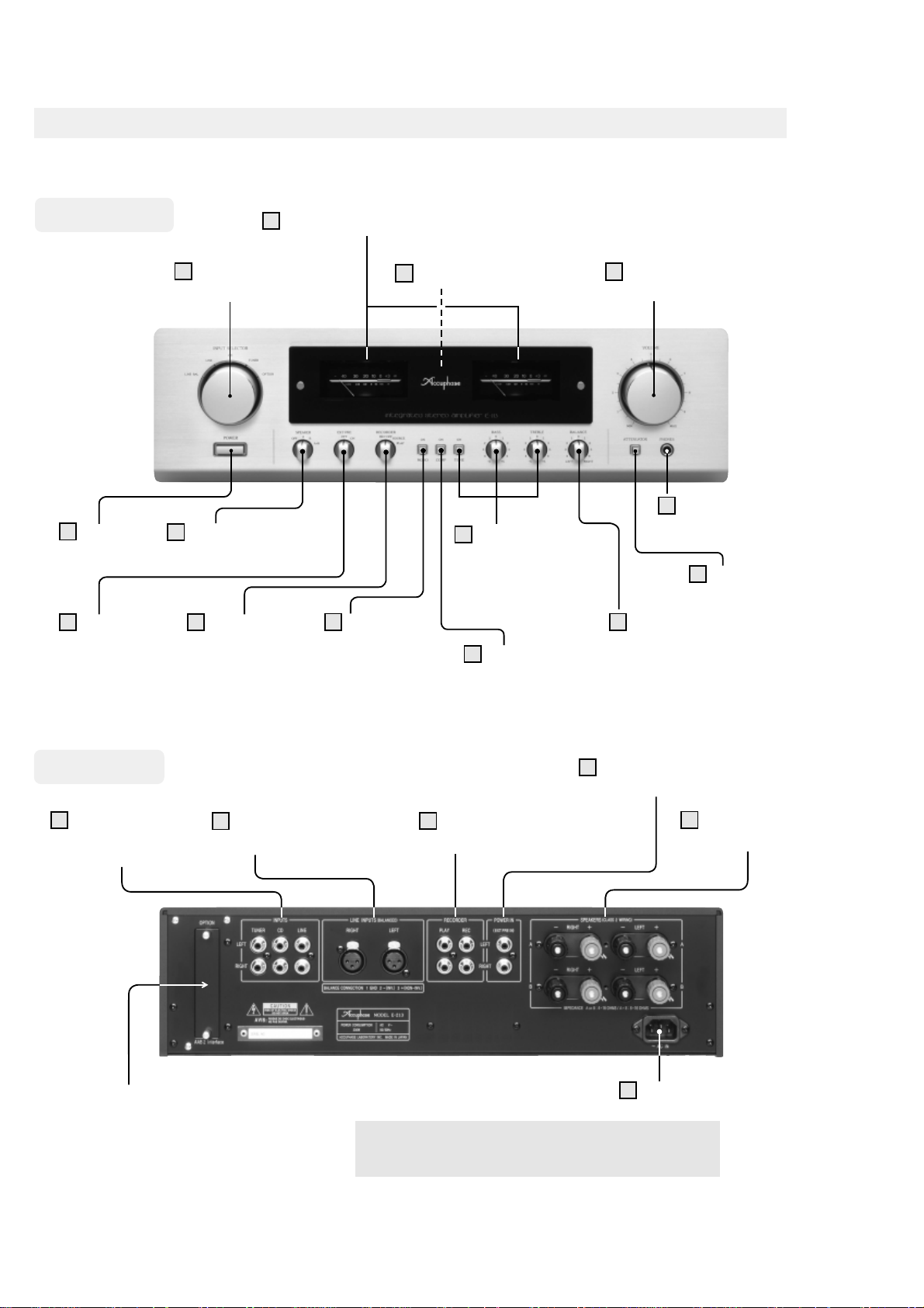
NAMING OF PARTS
n
ls
Front Panel
1
POWER
Power Switch
3
EXT PRE
Preamplifier/
Power Amplifier
Separation Selector
11
INPUT SELECTOR
Input Selector
2
SPEAKER
Speaker Selector
4
RECORDER
Recorder Selector
12
Power Meters (peak reading type)
13
Remote Sensor
5
MONO
Mono/Stereo
Mode Button
7
TONE ON/OFF,
BASS, TREBLE
Tone Control
On/Off Button
Bass, Treble Controls
6
COMP
Loudness
Compensator Button
14
VOLUME
Volume Control
10
8
BALANCE
Balance Control
PHONES
Headphone Jack
9
ATTENUATOR
Attenuator Butto
Rear Panel
15
INPUTS:
TUNER, CD, LINE
Line-level Input Jacks
Option Board Slot
16
LINE INPUTS (BALANCED)
Balanced Input connectors
18
POWER IN
Power Amplifier Input Jacks
17
RECORDER
Recorder REC/PLAY Jacks
20
※
This product is available in versions for 120/230 V AC.
Make sure that the voltage shown on the rear panel
matches the AC line voltage in your area.
19
AC Inlet
SPEAKERS A, B
Speaker Termina
1
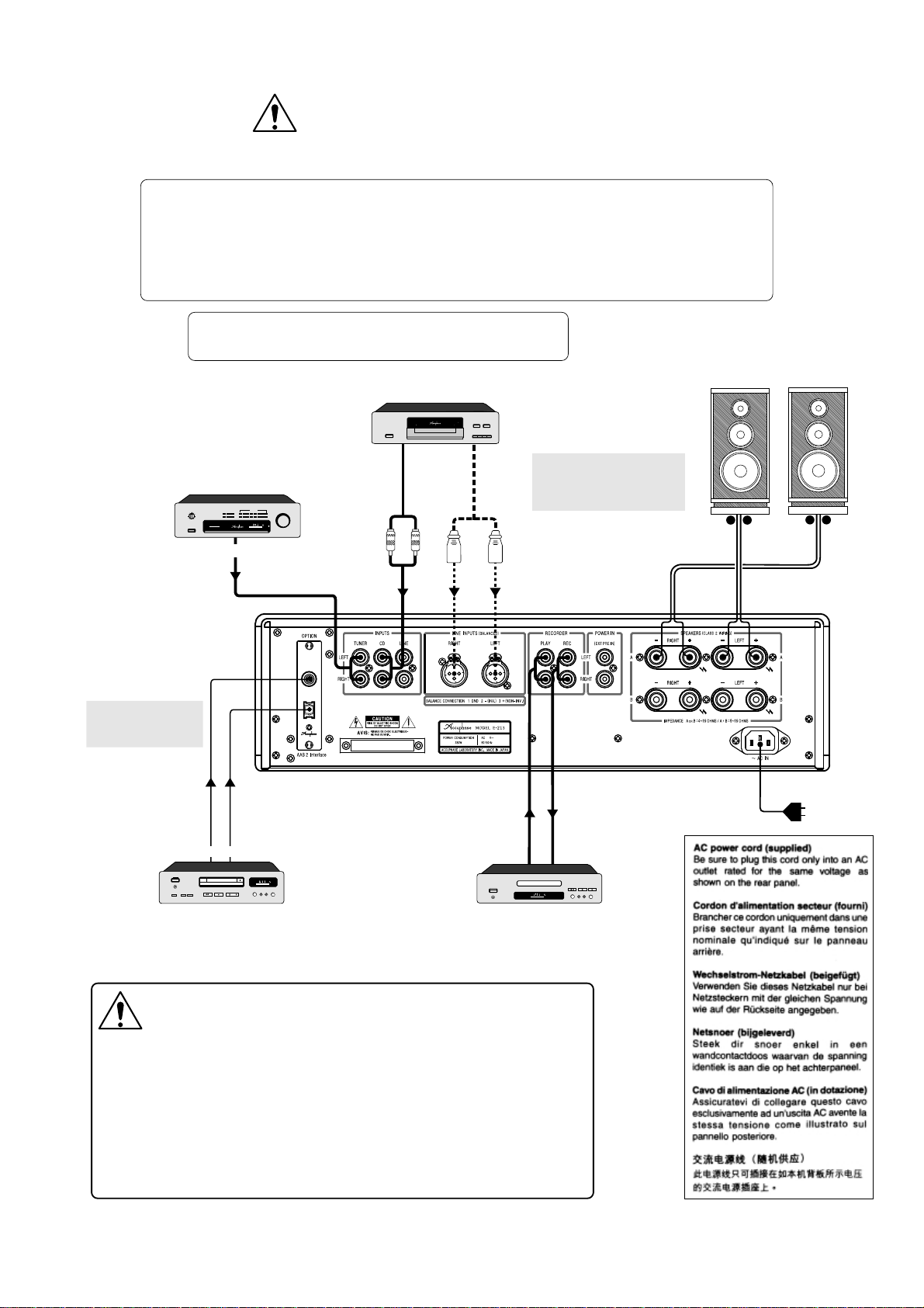
CONNECTIONS
CAUTION:
Before making connections, be sure to switch
the power to all components off.
Notes
●
For connection between the DAC-10 and digital equipment, use a 75-ohm coaxial cable or
optical fiber cable.
●
For analog input/output connections, use shielded audio cables and take care not to mix up
left and right channels.
●
Do not make connections to a component with balanced and unbalanced cables at the
same time. Otherwise ground loops may occur, which can cause noise.
Option board installation example shown in illustration
●
OPTION: Digital Input Board [DAC-10]
CD player
mmBcompa r dsc player
DP 5V
ANALOG
t t l l
m te eo t ner
m del T109V
ANALOG OUT
Tuner
Audio cables with
RCA-type plugs
tt on
OUTPUTS
Balanced
cables
*
Use shielded cables for audio
connections (2-conductor
shielded cables for balanced
connections).
Speakers
Left Right
+−
+−
D GITAL
INPUTS
COAX AL
OPTICAL
See "Option Boards"
for more information
on this connection.
75-ohm coaxial
cable
CD player, DAT recorder,
Optical fiber
cable
DIGITAL OUT
model DAC 10
LINE OUT
Recorder
MD recorder, or other
digital component
WARNINGS
●
This set relies on cooling with a natural flow of air between the ventilation
holes on the top and bottom. When installing the set, leave at least 10 cm of
space at both sides, the top and the back to allow for normal ventilation.
●
Do not place any object containing liquid (vases, flower pots, bottles with
cosmetics or chemicals, etc.) on top of the unit. If a spill occurs, there is a risk
of fire and electric shock.
●
If there is a problem with the unit or if malfunction occurs, always disconnect
the power cord from the AC outlet! This is absolutely essential, because simply
setting the power switch to OFF will not completely separate the unit from the
AC source.
LINE IN
2

Contents
Naming of Parts/Front Panel, Rear Panel ..................................................... 1
Connection ..................................................................................................... 2
Warnings/Accessories ................................................................................... 4
Parts and Functions ..................................................................................5 - 6
Operation ....................................................................................................... 7
Connection Examples ........................................................................... 8 - 9
Option Boards ....................................................................................... 10 - 11
Remote Control ............................................................................................ 12
Troubleshooting ........................................................................................... 12
Guaranteed Specifications ........................................................................... 53
Performance Curves .................................................................................... 54
Block Diagram .............................................................................................. 55
About the R mark
This mark indicates an important instruction that must be observed to prevent
the possibility of death or injury to persons or severe damage to the unit. To
ensure safe use of the product, make sure that such instructions are fully understood and observed.
WARNING:
Disregarding instructions bearing this mark incurs the risk of
death or severe injury.
R
CAUTION:
Disregarding instructions bearing this mark incurs the risk of
light injury or damage to the product.
ENGLISH
Table des matières
Noms des pièces/Panneau avant, Panneau arrière ................................ 1
Connexions ............................................................................................. 2
Avertissements/Accessoires ................................................................... 4
Nomenclature et fonctions ............................................................. 13 - 14
Fonctionnement .................................................................................... 15
Exemples de connexion ........................................................... 16 - 17
Cartes optionnelles ........................................................................ 18 - 19
Télécommande ..................................................................................... 20
Résolution des problèmes ..................................................................... 20
Caractéristiques techniques garanties .................................................. 53
Courbes de performance ...................................................................... 54
Schéma de principe .............................................................................. 55
Inhalt
Bezeichnung der Teile/Bedienfeld, Rückseite .......................................... 1
Anschlüsse ............................................................................................... 2
Warnungen/Zubehör ................................................................................ 4
Teile und Funktionen .......................................................................21 - 22
Bedienung .............................................................................................. 23
Anschlussbeispiele .................................................................... 24 - 25
Zusatz-Platinen ............................................................................... 26 - 27
Fernbedienung ....................................................................................... 28
Fehlersuche ........................................................................................... 28
Garantierte technische Daten ................................................................ 53
Leistungskurven ..................................................................................... 54
Blockdiagramm ...................................................................................... 55
Inhoud
Benaming van onderdelen/Voorpaneel, achterpaneel ........................... 1
Aansluitingen ........................................................................................... 2
Waarschuwingen/Accessoires ................................................................ 4
Onderdelen en functies ................................................................. 29 - 30
Bediening ............................................................................................... 31
Aansluitingsvoorbeelden ......................................................... 32 - 33
Optionele kaarten .......................................................................... 34 - 35
Afstandsbediening ................................................................................. 36
Oplossing van problemen ..................................................................... 36
Gewaarborgde specificaties .................................................................. 53
Prestatiecurves ...................................................................................... 54
Blokschema ........................................................................................... 55
Ce symbole a pour but d’indiquer la présence d’importantes instructions qui
doivent être respectées afin d’éviter les risques de décès ou de blessures
corporelles ou l’endommagement sérieux de cet appareil. Afin de garantir une
utilisation sûre de cet appareil, s’assurer que ces instructions ont bien été comprises et respectées.
AVERTISSEMENT :
Le non-respect des instructions portant ce symbole peut
provoquer des risques de décès ou de graves blessures
corporelles.
R
ATTENTION :
Le non-respect des instructions portant ce symbole peut
provoquer des risques de blesssures corporelles mineures
ou l’endommagement de l’appareil.
Über die Markierung R
A propos du symbole R
Diese Markierung deutet auf wichtige Anweisungen hin, welche unbedingt befolgt
werden müssen, damit lebensgefährliche oder sonstige Verletzungen von
Personen oder schwere Beschädigungen am Gerät vermieden werden. Um einen
sicheren Betrieb dieses Gerätes zu gewährleisten, müssen solche Anweisungen
vollkommen verstanden und beachtet werden.
R
WARNUNG:
Wenn Anweisungen mit dieser Markierung nicht beachtet
werden, kann dies zu lebensgefährlichen oder schweren Verletzungen führen.
VORSICHT:
Wenn Anweisungen mit dieser Markierung nicht beachtet
werden, kann dies zu leichten Verletzungen oder Beschädigungen am Gerät führen.
Het R teken
Dit teken wijst op een belangrijke richtlijn die moet worden gevolgd om het risico
op dood, letsels of ernstige schade aan het toestel te vermijden. Deze richtlijnen
moeten volledig worden begrepen en gevolgd om een veilig gebruik van dit
toestel te verzekeren.
WAARSCHUWING:
Niet-naleving van richtlijnen voorafgegaan door dit symbool
kan leiden tot de dood of tot ernstige letsels.
R
OPGELET:
Het negeren van instructies met deze aanduiding kan
lichamelijk letsel of schade aan het toestel tot gevolg
hebben.
FRANÇAISDEUTSCHITALIANO
NEDERLANDS
Sommario
Nomenclatura/Pannello anteriore, pannello posteriore ............................ 1
Collegamenti ............................................................................................ 2
Avvertimenti/Accessori ............................................................................. 4
Parti e funzioni ................................................................................ 37 - 38
Funzionamento ...................................................................................... 39
Esempi di collegamenti .............................................................. 40 - 41
Schede opzionali ............................................................................. 42 - 43
Telecomando .......................................................................................... 44
Localizzazione dei guasti ....................................................................... 44
Specifiche garantite ................................................................................ 53
Curve delle prestazioni ........................................................................... 54
Diagramma a blocchi ............................................................................. 55
Riguardo il simbolo R
Questo simbolo indica istruzioni importanti che devono essere rispettate al fine
di prevenire il rischio di morte, gravi lesioni personali o seri danni all’unità. Per
garantire l’utilizzo sicuro del prodotto, leggete attentamente e seguite tutte le
istruzioni.
AVVERTIMENTO:
In caso di mancato rispetto delle istruzioni contrassegnate
con questo simbolo sussiste il rischio di morte o gravi lesioni
R
personali.
ATTENZIONE:
In caso di mancato rispetto delle istruzioni contrassegnate
con questo simbolo sussiste il rischio di lievi lesioni personali
o danni al prodotto.
3

RWARNINGS
Before starting to use the unit, carefully read the separate
Instructions
nn
n Be sure to connect the power cord of the E-213 only to an AC outlet rated
nn
for the voltage shown on the rear panel.
nn
n Never use any other power cord except the supplied cord.
nn
nn
n Opening the unit is dangerous.
nn
nn
n Do not place the unit in an enclosed rack without any means of fresh air
nn
ventilation. Otherwise it could overheat, resulting in the risk of fire and
damage to the unit.
to ensure correct use.
Important Safety
RAVERTISSEMENTS
Avant de commencer à utiliser l’appareil, lire attentivement les
de sécurité importantes
nn
n Veuillez vous assurer de connecter le cordon d’alimentation du E-213 à
nn
une prise CA disposant du voltage indiqué sur le panneau arrière
uniquement.
nn
n Veuillez ne jamais utiliser de cordon d’alimentation autre que celui fourni.
nn
nn
n Ouvrir l’unité est dangereux.
nn
nn
n Veuillez ne pas placer l’unité dans un casier fermé ne disposant pas de
nn
moyens de ventilation ni d’air frais. Elle risquerait dans ce cas de surchauffer, ce qui pourrait entraîner un risque d’incendie ou d’endommager l’unité.
afin d’assurer une utilisation correcte.
Consignes
RWARNUNGEN
Lesen Sie sich vor Inbetriebnahme des Gerätes die separaten
heitshinweise
nn
n Vergewissern Sie sich, dass das Netzkabel des E-213 nur an eine Wechsel-
nn
strom-Steckdose angeschlossen wird, die mit der auf der Rückseite
des Gerätes aufgeführten Spannung belegt ist.
nn
n Verwenden Sie niemals ein anderes als das mitgelieferte Netzkabel.
nn
nn
n Das Öffnen des Gerätes ist gefährlich.
nn
nn
n Stellen Sie das Gerät nicht in einem geschlossenen Regal ohne jegliche
nn
Zufuhr von Frischluft auf. Dies könnte dazu führen, dass sich das Gerät
überhitzt, was das Risiko eines Brandes oder die Beschädigung des
Gerätes zur Folge haben könnte.
sorgfältig durch, damit ein einwandfreier Betrieb sichergestellt ist.
Wichtigen Sicher-
RWAARSCHUWINGEN
Lees de
Belangrijke veiligheidsinstructies
om van goed en veilig gebruik van het toestel verzekerd te zijn.
nn
n Sluit het netsnoer van de E-213 uitsluitend aan op een stopcontact waarop
nn
de op het achterpaneel aangegeven spanning staat.
nn
n Gebruik uitsluitend het meegeleverde netsnoer en nooit een ander snoer.
nn
nn
n Het openen van de behuizing is gevaarlijk.
nn
nn
n Plaats het toestel nooit in een gesloten rek zonder goede luchtventilatie.
nn
Het toestel kan oververhitten, met als gevolg het gevaar van beschadiging
of zelfs brand aan het toestel.
voor gebruik zorgvuldig door
nn
n Do not operate the EXT PRE button during playback.
nn
Always turn the volume fully down before setting the switch to ON or OFF.
nn
n Be sure to turn power off before connecting anything to the POWER IN
nn
jacks.
Accessories
m Instruction manual .................................................................. 1
m Important Safety Instructions ................................................. 1
m AC power cord (2 m) .............................................................. 1
m IEC R6 (size AA) batteries ..................................................... 2
m Remote commander RC-23 ................................................... 1
nn
n Ne pas utiliser la touche EXT PRE pendant la lecture.
nn
Toujours tourner la commande de volume complètement au minimum avant
de mettre le commutateur en position ON ou OFF.
nn
n S’assurer d’éteindre l’appareil avant d’effectuer une connexion aux prises
nn
POWER IN.
Accessoires
m Mode d’emploi ........................................................................1
m Consignes de sécurité importantes .......................................1
m Cordon d’alimentation secteur (2 m) ......................................1
m Piles IEC R6 (format AA) ....................................................... 2
m Télécommande RC-23 ...........................................................1
nn
n Betätigen Sie die EXT PRE-Taste nicht während der Wiedergabe.
nn
Drehen Sie die Lautstärke ganz herunter, bevor der Schalter auf ON oder
OFF gestellt wird.
nn
n Schalten Sie unbedingt den Strom aus, bevor ein Anschluss an die POWER
nn
IN-Buchsen erfolgt.
Zubehör
m Betriebsanleitung ................................................................... 1
m Wichtige Sicherheitshinweise ................................................ 1
m Wechselstrom-Netzkabel (2 m) ..............................................1
m IEC R6-Batterien (Größe AA) ................................................. 2
m Fernbedienung RC-23 ........................................................... 1
nn
n Bedien de EXT PRE-toets niet tijdens weergave.
nn
Stel het volume altijd op de minimumstand in voordat u deze toets op ON
of OFF zet.
nn
n Schakel de netspanning uit alvorens een component op de POWER IN-
nn
aansluitingen aan te sluiten.
Accessoires
m Gebruiksaanwijzing ................................................................ 1
m Belangrijke veiligheidsinstructies ...........................................1
m Netsnoer (2 m) ....................................................................... 1
m IEC R6 (AA) batterijen ........................................................... 2
m Afstandsbediening RC-23 ......................................................1
RAVVERTIMENTI
Prima di cominciare ad utilizzare l’unità, leggete attentamente le
Norme di Sicurezza
nn
n Assicuratevi che il cavo di alimentazione dell’E-213 sia collegato ad
nn
un’uscita CA di tensione nominale corrispondente a quella indicata sul
pannello posteriore.
nn
n Non usate mai cavi di alimentazione diversi da quello in dotazione.
nn
nn
n È pericoloso aprire l’unità.
nn
nn
n Non posizionate l’unità su una mensola senza possibilità di ventilazione
nn
da aria fresca altrimenti potrebbe surriscaldarsi causando il rischio di
incendio o danneggiamento dell’unità.
per assicurare l’impiego corretto della stessa.
4
Importanti
nn
n Non usate il tasto EXT PRE durante la riproduzione.
nn
Girate sempre il volume completamente verso il basso prima di collocare
l’interruttore su ON o OFF.
nn
n Assicuratevi di spegnere la corrente prima di effettuare dei collegamenti
nn
alle prese POWER IN.
Accessori
m Manuale delle istruzioni ......................................................... 1
m Importanti Norme di Sicurezza ............................................... 1
m Cavo di alimentazione CA (2 m) ............................................ 1
m Batterie IEC R6 (formato AA) .................................................2
m Telecomando RC-23 ..............................................................1
PARTS AND FUNCTIONS
POWER – Power Switch
1
Depress this switch to turn on the amplifier. Push once more to release
the switch and turn the amplifier off. For an interval of about 6 seconds
after power is turned on, there will be no sound from the speakers, due to the
action of the muting circuit.
SPEAKER – Speaker Selector
2
Serves to select two pairs of speakers connected to the “A” and “B”
speaker terminals.
OFF
Both speaker pairs are turned off, for example for headphone listening.
A, B
The respective speaker pair is active.
A + B
Both pairs of speakers are driven simultaneously. In this case, use speakers
with a rated impedance of 8 ohms or more, as both sets are connected in
parallel.
This position is also used for biwiring a single set of loudspeakers (using
separate cables for the low frequency range and mid/high frequency range).
EXT PRE – Preamplifier/Power Amplifier Separation Selector
3
This selector permits using the preamplifier section and the power
amplifier section of the E-213 separately.
OFF:
Normal operation. Preamplifier and power amplifier are not separated.
ON:
Preamplifier and power amplifier are separated.
Note
m Do not operate the selector during playback. Always turn the volume
fully down before setting the selector to ON or OFF.
m
m The E-213 does not have preamplifier output jacks.
RECORDER – Recorder Selector
4
REC OFF
Select this position during normal operation (when not recording). The amplifier
reproduces the selected program source, but the signal is not sent to the
“REC” outputs.
SOURCE
Select this position when wishing to record. The amplifier reproduces the
selected program source, and the signal is sent to the “REC” outputs.
PLAY
Select this position to reproduce the signal from a recorder connected to the
RECORDER “PLAY” inputs on the rear panel.
MONO – Mono/Stereo Mode Button
5
This button selects stereo or monophonic operation. When the button
is engaged, both channels are combined and the same signal is fed
to the left and right speakers. If the listening position is at approximately equal
distance from the speakers, the sound image should be centered.
m Button engaged: MONO
m Button disengaged: STEREO
Note
When the MONO position is selected, the recording outputs are also
switched to a monophonic signal.
COMP – Loudness Compensator Button
6
This button serves to restore natural tonal balance at low listening
levels. The human ear becomes less sensitive to frequency extremes
as loudness decreases. This often causes the sound to be perceived as thin
or deficient, especially in the bass range. The COMP switch makes up for this
effect by boosting the low range (+6 dB at 200 Hz).
✽ This boost is applied at a –30 dB setting of the volume control. When you
turn up the volume control, the compensation is automatically reduced.
m Button engaged: ON
m Button disengaged: OFF
TONE, BASS, TREBLE – Tone Controls
7
TONE – Tone Control On/Off Button
m
m Button engaged: ON
m Button disengaged: OFF
✽ When the button is set to ON, the BASS and TREBLE controls can be
used.
✽ When the button is set to OFF, frequency response will be flat, regardless
of the setting of the BASS and TREBLE controls.
BASS – Bass Control
Turning this control to the right from the center (0) position boosts the low
frequency range, and turning the control to the left attenuates it.
m Turnover frequency: 300 Hz
m Adjustment range: ±10 dB at 50 Hz
TREBLE – Treble Control
Turning this control to the right from the center (0) position boosts the
upper frequency range, and turning the control to the left attenuates it.
m Turnover frequency: 3 kHz
m Adjustment range: ±10 dB at 20 kHz
BALANCE – Balance Control
8
This control serves to adjust the left/right stereo balance.
mm
m Normally, the control should be left in the center (0) position.
m
ATTENUATOR – Attenuator Button
9
This button serves to quickly reduce the output level of the amplifier.
The attenuation level is –20 dB.
m Button engaged: ON
m
m Button disengaged: OFF
PHONES – Headphone Jack
10
Stereo headphones can be plugged into this jack.
✽ When wishing to listen with headphones only, set the SPEAKERS selector
to OFF.
✽ Adjust the listening level with the main volume control.
✽ Use headphones with an impedance between 8 and 100 ohms.
Note
If the EXT PRE selector is set to “ON” to separate the preamplifier and
power amplifier, the signal at this headphone jack comes from the power
amplifier section. Therefore the volume should be adjusted at the connected
external preamplifier.
INPUT SELECTOR – Input Selector
11
Serves to select the various program sources connected to the rearpanel inputs. The corresponding buttons on the remote control RC-23
can also be used.
TUNER, CD, LINE
Select components connected to the conventional unbalanced inputs on the
rear panel.
LINE-BAL
Select components connected to the balanced inputs on the rear panel.
OPTION
Component connected to the option board in the OPTION slot on the rear
panel.
m
m See the section “Option Boards” in these instructions for more information.
✽ This rotary selector has no marking or end stopper (it can be turned
continuously).
ENGLISH
5
ENGLISH
Power Meters (peak reading type)
12
The meter scale indicates the output level in dB (decibel) and is also
calibrated in watts for an 8-ohm load. With a 4-ohm load, the figures
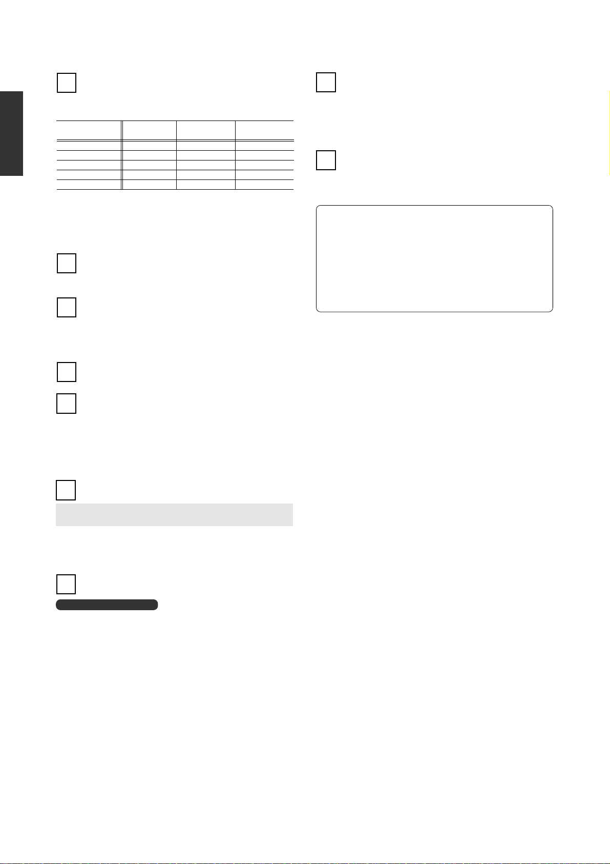
must be doubled, and with a 16-ohm load halved. Output levels with a sinewave signal for various loads are shown below.
Output indication
(dB/%)
0 dB: 100 % 180 W 90 W 45 W
–10 dB: 10 % 18 W 9 W 4.5 W
–20 dB: 1 % 1.8 W 900 mW 450 mW
–30 dB: 0.1 % 180 mW 90 mW 45 mW
–40 dB: 0.01 % 18 mW 9 mW 4.5 mW
The meters are peak-reading designs, which enables them to precisely follow
the rapid changes in amplitude and frequency that are common with music
signals. To make for easier reading, the decay time of the meters is set to a
lower value than the rise time. If the program source contains noise or a large
amount of transients, the meter indication and the aural volume impression
may differ slightly.
Remote Sensor
13
The infrared signals from the supplied remote commander RC-23 are
received by this sensor. When using the remote commander, point
the transmitter in the direction of this sensor.
VOLUME – Volume Control
14
Turning this control clockwise increases the volume level. The control
can also be operated with the remote commander RC-23.
Caution: When changing the setting of the EXT PRE selector ON/OFF,
when changing program sources, and when turning the power on and
off, the volume control should always be fully turned down.
INPUTS: TUNER, CD, LINE – Line-level Inputs
15
These inputs are conventional unbalanced line-level input jacks.
4-ohm load 8-ohm load 16-ohm load
SPEAKERS A, B – Speaker Terminals
19
Two pairs of speakers can be connected to the A and B terminals.
✽ Use speakers with a rated impedance of 4 to 16 ohms.
✽ When driving both sets of speakers simultaneously, use speakers with
a rated impedance of 8 to 16 ohms.
✽ For a biwiring arrangement, connect the cables for the low frequency range
and mid/high frequency range separately to terminals A and B.
AC Inlet
20
Insert the supplied power cord into this connector and plug the other
end into an AC outlet.
RWARNING
m Do not use the unit with any other than the supplied power cord.
m The shape of the AC inlet and the plug of the supplied power cord depend
on the destination country of the unit. Using any other type of cable
except the supplied power cord poses the risk of fire and damage.
m This product is available in versions for 120/230 V AC. Make sure that
the voltage shown on the rear panel matches the AC line voltage in your
area.
m Opening the unit involves a severe risk of electric shock.
m If the unit does not operate, the internal fuse may have blown. Never
attempt to replace the fuse yourself. Be sure to contact your Accuphase
dealer or an authorized service station.
LINE INPUTS (BALANCED) – Balanced Inputs
16
These inputs are conventional balanced high-level input jacks.
The pin assignment of the connectors is as follows.
Make sure that the source component uses the same pin assignment.
A: Ground
B: Inverted (–)
C: Non-inverted (+)
Balanced cables are available from Accuphase.
RECORDER – Recorder REC/PLAY Jacks
These jacks serve for connection of a recorder.
17
“PLAY” jacks Ù LINE OUT jacks of recorder
“REC” jacks Ù LINE IN jacks of recorder
✽ The output signal at the REC jacks is not affected by the volume and
compensator settings of the amplifier.
✽ Keep in mind that when the MONO button is engaged, the recording output
will be monophonic.
POWER IN – Power Amplifier Input Jacks
18
POWER IN (EXT PRE IN)
These jacks permit using the power amplifier section separately.
m When the EXT PRE selector has been set to “ON” for separating the
preamplifier and power amplifier of the E-213, these jacks serve as power
amplifier input jacks. Input source switching, volume adjustment, and other
preamplifier functions must be performed at the external equipment.
Caution: Before connecting the cable, be sure to turn power OFF.
6

OPERATION
RCAUTION
m Before making connections, be sure to switch the power to the E-213 and all other components off. Especially when connecting or disconnecting
a cable at the POWER IN jacks, the power to the E-213 must be off.
m Do not operate the EXT PRE selector during playback. Always turn the volume fully down before setting the switch to ON or OFF.
Before starting to use the unit, set the controls as follows.
m V
OLUME: Turned fully down (counterclockwise)
m SPEAKER: Set to the position for the desired speaker pair
m EXT PRE: OFF
m RECORDER: REC OFF
m BALANCE: Center position
m MONO, COMP, TONE, ATTENUATOR: OFF (button disengaged
Listening to Compact Discs (Via Analog Input)
Connect the analog output of the CD player to the CD (or TUNER or LINE)
input jacks on the rear panel. If the CD player has balanced outputs, it is
recommended to use balanced cables and connect them to the balanced LINE
INPUTS connectors.
For playback, perform the following steps
A Confirm that the VOLUME control is turned to minimum. Then switch on the
CD player and the amplifier.
B Use the INPUT SELECTOR on the amplifier or on the remote commander
C Operate the CD player and adjust the desired listening level with the
D If desired, use the MONO button to check that the sound is centered between
)
to select the “CD” position (or the position corresponding to the input in
use).
VOLUME control.
the two speakers, and check the action of the tone controls, loudness
compensator, and attenuator.
ENGLISH
Listening to Radio Broadcasts
Connect the output of the tuner to the TUNER (or CD or LINE) input jacks on
the rear panel. If the tuner has balanced outputs, it is recommended to use
balanced cables and connect them to the balanced LINE INPUTS.
Recording and Playback With a Recorder
Confirm that the inputs and outputs of the recorder are properly connected to
the RECORDER jacks on the rear panel of the E-213.
REC jacks Ù LINE IN jacks of recorder
PLAY jacks Ù LINE OUT jacks of recorder
Playback
To hear the playback sound, set the RECORDER selector to the PLAY position
and start playback at the recorder.
✽ For playback only, a recorder may also be connected to any other line input
of the E-213.
Recording
For recording, perform the following steps.
A Select the desired program source with the INPUT SELECTOR and check
that it is reproduced properly over the loudspeakers.
B Set the RECORDER selector to “SOURCE”. The signal of the selected
program source is now supplied at the recording outputs of the amplifier.
C Start the recorder. The sound heard over the loudspeakers is now recorded
on the recorder.
D The volume, attenuator, tone control, and compensator settings of the
amplifier do not affect the recording output. The volume can therefore be
turned all the way down if desired. The recording level must be adjusted
with the input controls of the recorder.
E By setting the RECORDER selector to the PLAY position during recording,
the actual sound as recorded on the tape can be monitored (when using a
three-head tape recorder).
Note
When the MONO button is set to ON (monophonic mode), the recording output
will also be monophonic.
Set the INPUT SELECTOR to the required position and perform the same
steps as described for CD playback. After tuning to the desired station, adjust
the listening level with the VOLUME control.
Tuner Recording While Power Is Off
While power to the E-213 is off, the signal from the TUNER inputs is always
connected to the RECORDER REC outputs, regardless of the INPUT
SELECTOR and the RECORDER selector settings. Therefore it is possible to
carry out unattended recording of the source connected to the tuner inputs
with a timer even without turning on the amplifier.
Note
Do not turn power to the E-213 on while unattended recording is in progress.
If you turn the E-213 on, the muting circuit will become active and the
recording output signal will be interrupted. Before turning power on, verify
that any recording that was carried out is completed.
7

Playback With DG-38 Connected
ENGLISH
The Digital Voicing Equalizer DG-38 can be connected to the E-213, allowing highly precise sound field compensation during playback
of program sources.
m An analog input board and analog output board must be installed in the option board slots of the DG-38.
m For details on connection and operation of the DG-38, please refer to the instruction manual of the DG-38.
Connection Examples
The DG-38 is connected to the RECORDER jacks of the E-213
Right speaker
✽ Select E-213 source input with
the INPUT SELECTOR.
When the RECORDER selector is set to
NOTE:
SOURCE or REC OFF, the DG-38 is
taken out of the signal path which may
cause a sudden increase in volume.
Front panel
Set RECORDER selector
to
.
Left speaker
Source component
Analog
output
Use audio cables with RCA-type plugs
E-213 REC Ù AI2-U1
E-213 PLAY Ù AO2-U1
DG-38 rear panel
Input board: AI2-U1 Output board: AO2-U1
Install the AI2-U1 and AO2-U1 in the DG-38 option slot.
✽ Set switch on AI2-U1 board to 96 kHz.
✽ Set INPUT
SELECTOR
of DG-38 to
“Analog in-1”.
8
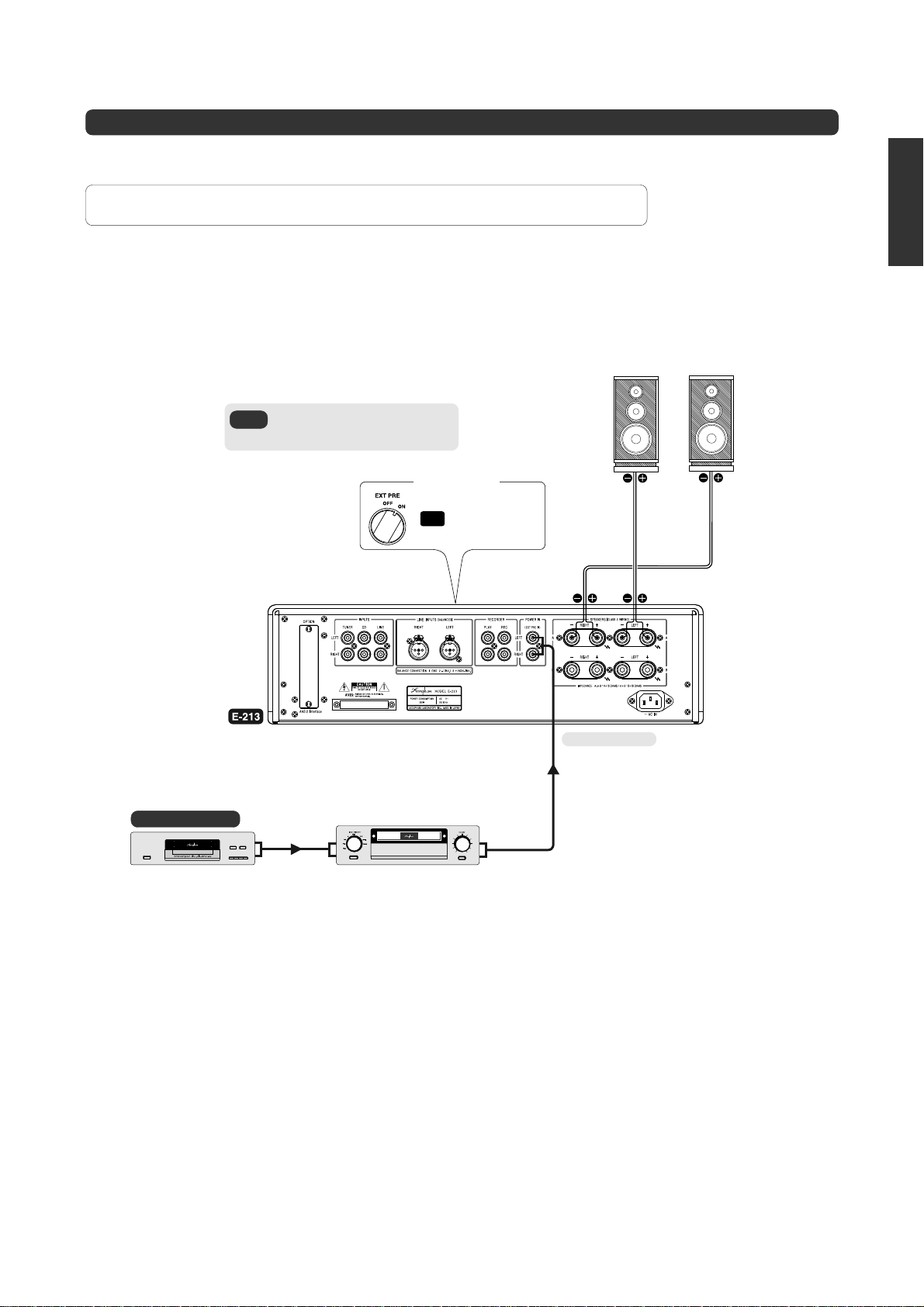
Playback With an External Preamplifier
You can set the EXT PRE selector to ON to separate the preamplifier and power amplifier of the E-213, and use an external preamplifier
or A/V amplifier with the power amplifier of the E-213. An example of such a connection is shown below.
RCAUTION:
m Connect the output of the external preamplifier to the POWER IN jacks of the E-213.
m Only the power amplifier of the E-213 is used in this case. The preamplifier is inactive. Input source
switching, volume adjustment, and other preamplifier functions must be performed at the external equipment.
connections.
If you set the EXT PRE selector to OFF,
NOTE:
the E-213 will operate normally (using
the internal preamplifier).
Front panel
Be sure to turn power to all components off before making
Set EXT PRE selector to
ON
ENGLISH
Left speaker Right speaker
Source component
External preamplifier,
A/V amplifier, etc.
Preamplifier output
To POWER IN jacks
Audio cable with
RCA-type plugs
9
OPTION BOARDS
ENGLISH
Three types of option boards can be used in the E-213: the Digital Input Board DAC-10, the Analog Disc Input Board AD-9, and the Line Input Board LINE-9. These
boards can be installed in the rear-panel slot as required.
m The Analog Disc Input Board AD-10 and the Line Input Board LINE-10 can also be used.
USING AN OPTION BOARD
Playback of CDs or similar with digital input
Install the Digital Input Board DAC-10.
Caution: Be sure to turn power to the E-213 off before installing or
removing an option board.
✽ The board can handle digital output signals from a CD player, DAT recorder,
MD recorder or another digital component with a sampling frequency of up
to 96 kHz.
The connection can be made with coaxial or optical fiber cable.
Digital Input Board DAC-10
This board can be used for optical and/or coaxial input of
digital music signals from source components with digital
output.
Connection cables
COAXIAL: For 75-ohm coaxial cable
OPTICAL: For Toslink optical fiber cable
Guaranteed specifications, standards
Input format: EIAJ CP-1201/AES-3 compliant
Sampling frequency:
Digital input: COAXIAL 0.5 Vp-p, 75 ohms
(OPTICAL input has automatic priority.)
32 – 96 kHz
OPTICAL –27 to –15 dBm
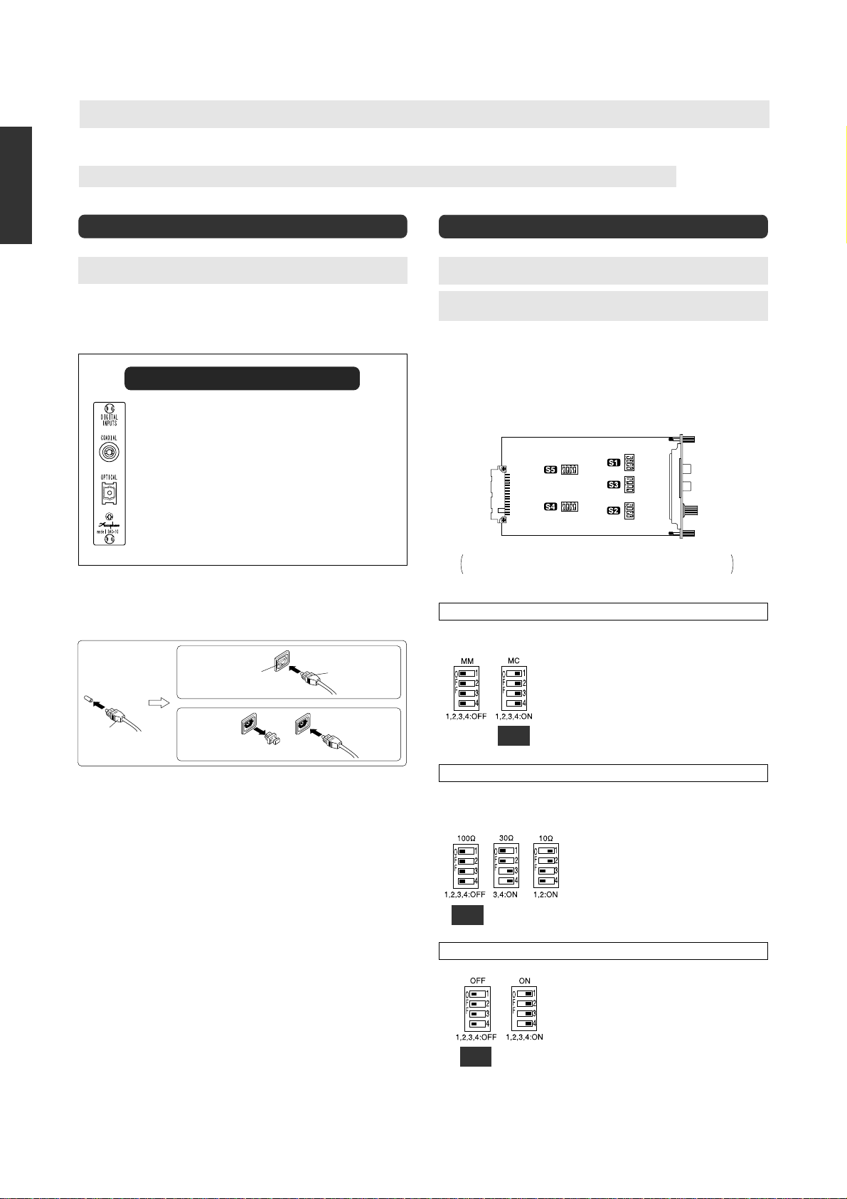
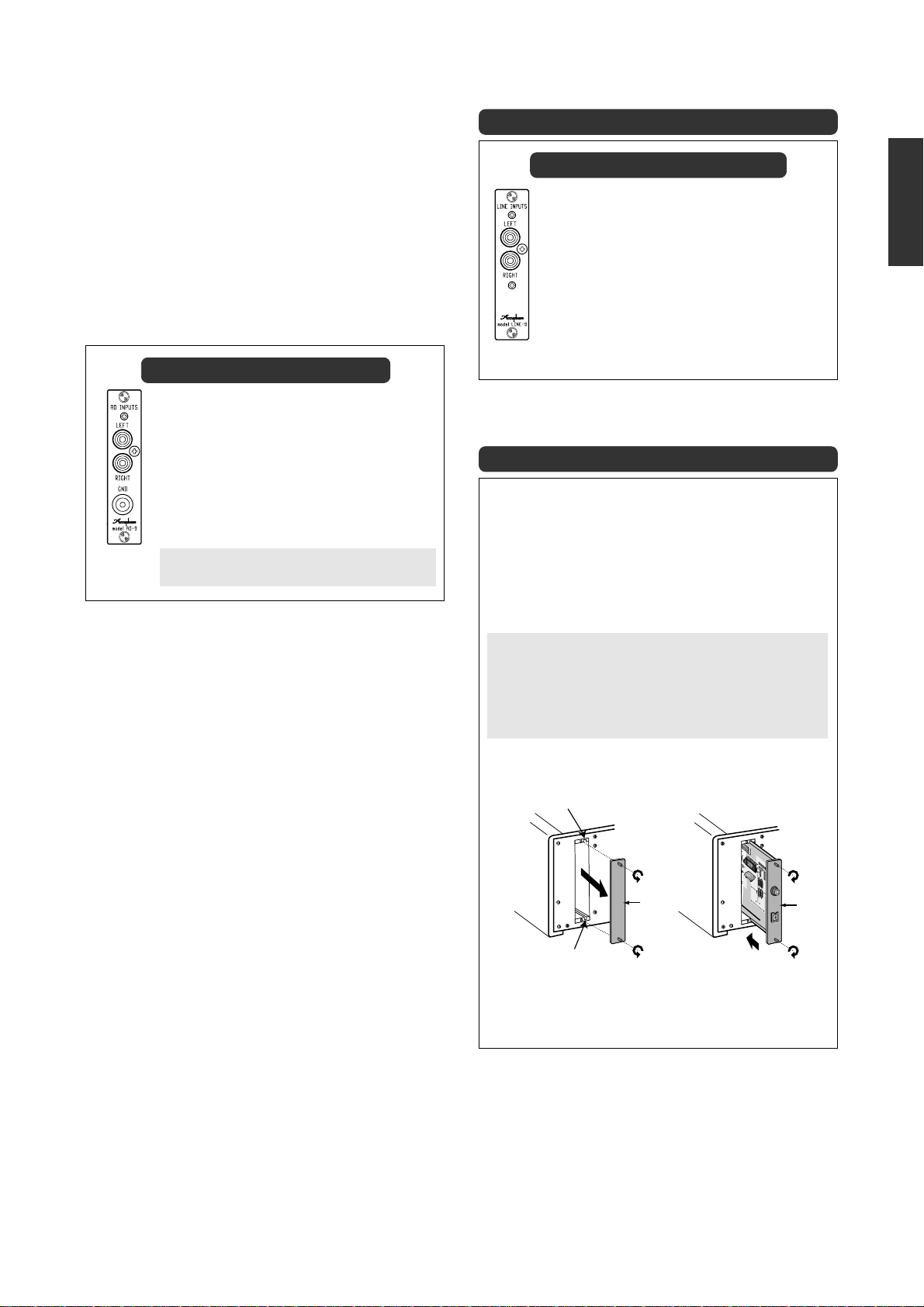
Analog Disc (AD) Input
Install the Analog Disc Input Board AD-9 (or AD-10).
Caution: Be sure to turn power to the E-213 off before installing or
removing an option board.
Before inserting the board, the following settings must be made using
the DIP switches on the board.
Note: Use a sharp pointed object to move the switch levers and make
sure that the levers are set fully to one side. If switch settings not
specified here are selected, correct performance will not be
achieved.
A S1, S2: MM/MC selection
B S3: Input impedance selection for MC: 10/30/100 ohms
C S4, S5: Subsonic filter ON/OFF
AD-9 component side
The illustration shows the position of the switches on the board.
The switch position is identical for the AD-9 and AD-10.
Connection cables
COAXIAL: Use a 75-ohm coaxial cable with RCA plugs.
OPTICAL: This is a connector for EIAJ standard Toslink optical fiber cable.
Insert plug firmly into connector
with lettering facing up
Lettering
Insert plug firmly into connecto
with lettering facing up
Remove protective cover from
connector
Plug
Connector with shutter
Push inwards to open
shutter
Connector with
protective cover
Pu l protector off plug tip
Playback
a Verify that the VOLUME control is turned fully down and then turn on the
E-213 and the other components. Select the OPTION position of the input
selector. (This position is for the slot where the DAC-10 is installed.)
b Set the source component to the play condition and adjust the volume to a
suitable level.
Note
When both the COAXIAL and the OPTICAL inputs are connected, the OPTICAL
connector is automatically given priority.
m When signals are present at both connectors, the source connected to the
OPTICAL (Toslink optical fiber) input will be heard.
m To play back the signal from the component connected to the COAXIAL
connector, disconnect the OPTICAL input or turn power to the component
connected to the OPTICAL input off.
m If a signal appears at the OPTICAL input during playback of the signal from
the COAXIAL input, playback will switch to the OPTICAL input.
A
S1, S2: MM/MC equalizer gain selection
MM: For moving magnet cartridges with high
output
Gain: 36 dB
Input impedance: 47 kilohms
MC: For moving coil cartridges with low output
Gain: 62 dB
Factory
default
setting
B
S3: MC input impedance selector
Factory
default
setting
C
S4, S5: Subsonic filter on/off
Factory
default
setting
Input impedance: As selected with S3
m Be sure to set both the S1 and S2 switches to the
same position.
As a general guideline, set this switch according
to the rated internal impedance of the MC cartridge.
20 ohms or more: 100 : position
Less than 20 ohms: 30 : or 10 : position
m Generally, the input impedance setting should
be about 2 to 3 times the rated cartridge
impedance. However, since the requirements
of some cartridges may vary, the final setting
should be determined by ear.
m The S3 switch affects both the left and right
channels.
This filter has a cut-off frequency of 25 Hz and a
steep attenuation slope of –12 dB/octave. It cuts
off unwanted subsonic signal components without
affecting the audible range. Removing subsonic
noise components is useful for example to stop
excessive woofer excursions caused by record
warps, turntable rumble, etc.
m Be sure to set both the S4 and S5 switches to
the same position.
10
n Connect the output cable from the analog record player correctly to
the input jacks on the board. Also connect the ground cable from the
analog record player to the ground (GND) terminal on the board.
Playback
a Verify that the VOLUME control is turned fully down, and then turn power to
the E-213 and the other components on. Select the OPTION position of the
input selector. (This position is for the slot where the AD-9 or AD-10 is
installed.)
b Lower the stylus onto the record and adjust the volume to a suitable level.
c If the record is notably warped or if there are excessive woofer excursions
caused by turntable rumble, enabling the subsonic filter can help to reduce
noise.
Analog Disc Input Board AD-9
This board serves for playback of analog records. It contains a
high-performance, high-gain phono equalizer. The board can be
used with any type of phono cartridge.
m By installing two of these boards, two different phono cartridges
can be connected at the same time.
LEFT, RIGHT analog record player input jacks
Connect the output cable from the analog record player to these
jacks.
GND terminal
Connect the ground cable from the analog record player to this
terminal.
Before inserting the board, the DIP switches must be set
to the required positions.
OTHER OPTION BOARD
Line Input Board LINE-9
This option board provides an additional set of analog line
inputs that are similar to the INPUTS of the E-213. They can
be used to connect a CD player, tuner, or other component
with analog output.
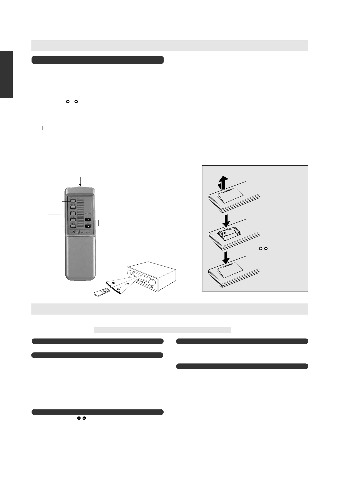
OPTION BOARD INSTALLATION
A Set the power switch of the E-213 to OFF.
B On the rear panel, remove the panel covering the option slot.
C Insert the option board by sliding it into the top and bottom guide rails of
the option board slot. When the board touches the internal connector,
give it a slight push until the board is firmly seated. (The board must be
flush with the panel.)
D Secure the board with the two screws at the top and bottom.
ENGLISH
RCAUTION
m Be sure to turn the E-213 OFF before inserting or removing any
option board. Otherwise damage to the board or to the amplifier can
occur.
m Take care not to touch the components, the printed circuit side, or
the connector edge of the board, to prevent possible contact problems
or damage. Hold the board only by the edges or the rear panel.
m Be sure to securely fasten the board with the two screws. Otherwise
insufficient grounding may lead to function problems and damage.
Guide rail
Subpanel
Guide rail
✽ The illustration shows the
DAC-10.
Option
board
11
REMOTE CONTROL
ENGLISH
A INPUT
SELECTOR
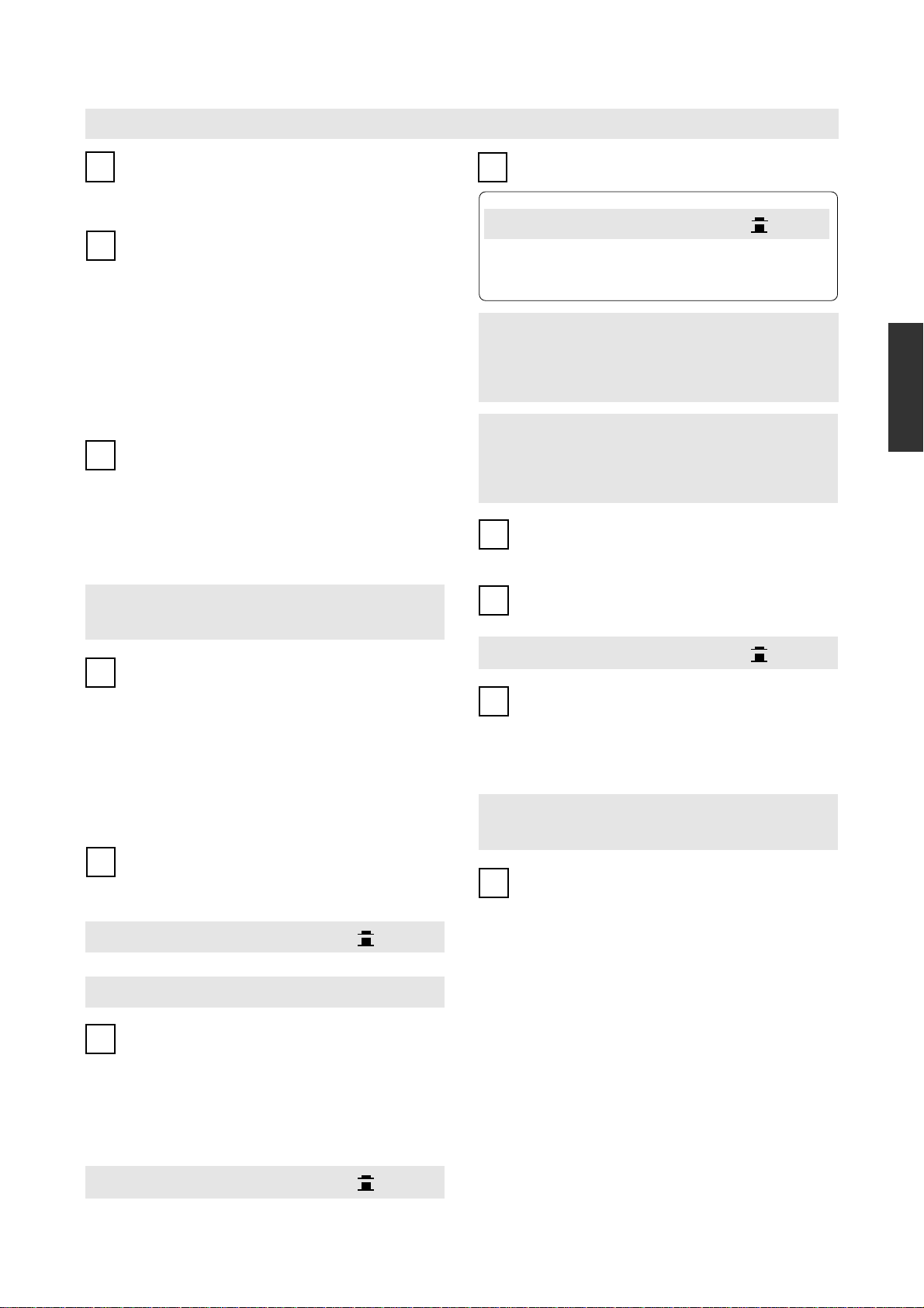
Using the Remote Commander RC-23
The supplied remote commander RC-23 can be used to operate the E-213 from anywhere
in the room.
A INPUT SELECTOR buttons
The set of INPUT SELECTOR buttons on the remote commander offers identical
functionality as the INPUT SELECTOR on the E-213. Simply press a button for the
desired program source. The corresponding LED on the E-213 lights up.
B Volume adjustment
Press the VOLUME
the volume. When a button is pressed, the VOLUME control knob on the E-213 turns
accordingly.
or button on the remote commander to increase or decrease
Operation
To operate the unit, point the transmitter at the tip of the remote commander towards the
sensor
on the E-213. The effective operation range is shown in the illustration below.
13
m Take care not to drop the remote commander or spill any liquid on it.
m Do not subject the remote commander to high temperatures or humidity, such as in
locations exposed to direct sunlight or close to heating appliances, etc.
Transmitter
(point at sensor on E-213)
B VOLUME control
buttons
About Batteries
nn
n Battery replacement
nn
The batteries will last for about 8 months with normal use. When you notice that the
effective range of the remote commander decreases, you should replace the batteries.
When the batteries are totally exhausted, pressing any of the buttons will have no effect.
The battery type is IEC R6 (size AA). Always replace both batteries together.
RCAUTION
Observe the following precautions to prevent battery leakage or damage.
m Insert the batteries with correct polarity, as marked inside the case.
m Do not use a mixture of old and new batteries together.
m Use only the specified battery type, and do not mix different battery types.
m Remove the batteries if the remote commander will not be used for a long time.
m If battery leakage has occurred, contact your Accuphase dealer or an authorized service
station. If battery fluid has come into contact with your body, wash the affected part with
plenty of water.
RWARNING
Never try to charge regular dry cell batteries not designed for recharging. Otherwise there is
a risk of explosion, leakage, fire, and injury.
Replacing the Batteries
Push the tab in the arrow direction to open the
battery case.
Insert two IEC R6 (size AA) batteries with
polarity.
correct
Push the lid down until it snaps into place.
TROUBLESHOOTING
If there seems to be a problem with the unit, please check the following points first. If the problem persists, contact your Accuphase dealer or an authorized service station.
RCAUTION
No power.
m Is the power cord plugged in correctly?
No sound.
m Are the program source components turned on?
m Check the setting of the SPEAKER selector.
m Check the setting of the EXT PRE selector.
m Are all components and the loudspeakers connected correctly?
m Is the INPUT SELECTOR set to the correct position?
m Is the RECORDER selector set to the correct position?
Stereo image is fuzzy.
m Check whether speaker
... When set to OFF, no sound will be heard.
... When set to ON, the preamplifier and power amplifier sections are
separated, and no sound will be heard if no component is connected to
the POWER IN jacks.
Before changing any connections, be sure to turn the power to all components OFF.
Remote commander does not operate.
m Check whether batteries are properly inserted.
m Replace the batteries with fresh ones.
m Remove any obstacles between the commander and the unit.
No sound in one channel.
m Are all components and the loudspeakers connected correctly?
m Is the BALANCE control set correctly?
m Try reversing the left and right speaker cables.
m Try reversing the left and right input cables.
polarity is reversed in one channel.
Still no sound in the same channel:
... Check the cables and the loudspeaker itself.
No sound in the other channel:
... The E-213 or source component may be defective.
Still no sound in the same channel:
... The E-213 may be defective.
No sound in the other channel:
... Cables or source component may be defective.
12
NOMENCLATURE ET FONCTIONS
POWER – Interrupteur d’alimentation
1
Appuyer sur cet interrupteur pour mettre l’amplificateur sous tension.
Appuyer à nouveau sur l’interrupteur pour l’éteindre. Pendant un
intervalle d’environ 6 secondes après la mise sous tension, aucun son n’est
émis des enceintes, à cause de l’activation du circuit de sourdine.
SPEAKER – Sélecteur d’enceinte
2
Sert à sélectionner deux paires d’enceintes connectées aux bornes
d’enceinte “A” et “B”.
OFF
Les deux paires d’enceintes sont désactivées, par exemple pour l’écoute par casque.
A, B
La paire d’enceinte respective est activée.
A + B
Deux paires d’enceintes sont entraînées simultanément. Si cela se produit,
utiliser des enceintes ayant une impédance nominale de 8 ohms ou plus, car
les deux paires sont connectées en parallèle.
Cette position est également utilisée pour le bicâblage d’une simple paire
d’enceintes (utilisant des câbles séparés pour les gammes de fréquences
basses et une autre pour les fréquences moyennes/hautes).
EXT PRE – Sélecteur de séparation du préamplificateur/
amplificateur de puissance
3
Ce sélecteur permet d’utiliser séparément les sections préamplificateur
et amplificateur de puissance du E-213.
OFF :
Fonctionnement normal. Le préamplificateur et l’amplificateur de puissance
ne sont pas séparés.
ON :
Le préamplificateur et l’amplificateur de puissance sont séparés.
Remarque
m Ne pas utiliser le sélecteur pendant la lecture. Tourner toujours la com-
mande de volume complètement au minimum avant de régler le sélecteur en position ON ou OFF.
m Le E-213 n’est pas équipé de prises de sortie préamplificateur.
RECORDER – Sélecteur d’enregistrement
4
REC OFF
Sélectionner cette position pendant le fonctionnement normal (hors enregistrement). L’amplificateur reproduit la source de programme sélectionnée, mais
le signal n’est pas envoyé aux sorties “REC”.
SOURCE
Sélectionner cette position lorsqu’on veut enregistrer. L’amplificateur reproduit
la source de programme sélectionnée, et le signal est envoyé aux sorties “REC”.
PLAY
Sélectionner cette position pour reproduire le signal d’un enregistreur connecté
aux entrées RECORDER “PLAY” du panneau arrière.
MONO – Touche de mode mono/stéréo
5
Cette touche sélectionne le fonctionnement stéréo ou mono. Lorsque la
touche est enfoncée, les deux canaux sont combinés et le même signal
est émis aux enceintes gauche et droite. Si la position d’écoute est approximativement à distance égale des enceintes, l’image sonore devrait être centrée.
m Touche activée : MONO
m T
ouche désactivée : STEREO
Remarque
Lorsque la position MONO est sélectionnée, les sorties d’enregistrement
sont également commutées sur mono.
COMP – Touche de compensation physiologique
6
Cette touche sert à restaurer l’équilibre de tonalité naturelle aux
niveaux d’écoute faibles. L’oreille humaine devient moins sensible
aux fréquences extrêmes lorsque la compensation diminue. Cela crée
souvent une perception de son faible ou déficiente, en particulier dans la
gamme des basses fréquences. La touche COMP compense cet effet en
améliorant la gamme inférieure (+6 dB à 200 Hz).
✽ Cette accentuation est appliquée à un réglage de –30 dB de la commande
de volume. Lorsque le niveau de volume est augmenté, la compensation
est réduite automatiquement.
m Touche activée : ON
m T
ouche désactivée : OFF
TONE, BASS, TREBLE – Commande de tonalité
7
TONE – Touche de commande de tonalité activée/désactivée
m Touche activée : ON
m T
ouche désactivée : OFF
✽ Lorsque la touche est placée en position ON, les commandes BASS et
TREBLE peuvent être utilisées.
✽ Lorsque la touche est en position OFF, la réponse en fréquence sera
plate, indépendamment du réglage des commandes BASS et TREBLE.
BASS – Commandes des graves
Lorsque cette commande est tournée vers la droite à partir de la position centrale (0), la gamme des basses fréquences est accentuée et lorsque cette
commande est tournée vers la gauche, les basses fréquences sont atténuées.
m Fréquence de retournement : 300 Hz
m
m
m Plage de réglage : ±10 dB à 50 Hz
TREBLE – Commande des aiguës
Lorsque cette commande est tournée vers la droite à partir de la position
centrale (0), la gamme des hautes fréquences est accentuée et lorsque cette
commande est tournée vers la gauche, les hautes fréquences sont atténuées.
m Fréquence de retournement : 3 kHz
m Plage de réglage : ±10 dB à 20 kHz
BALANCE – Commande d’équilibre
8
Cette commande sert à régler l’équilibre stéréo gauche/droite.
m
m Normalement, la commande doit être en position centrale (0).
ATTENUATOR – Touche d’atténuateur
9
Cette touche sert à réduire rapidement le niveau de sortie de l’ampli-
ficateur. Le niveau d’atténuation est de –20 dB.
m Touche activée : ON
m Touche désactivée : OFF
PHONES – Prise casque
10
Un casque stéréo peut être branché à cette prise.
✽ Lorsqu’on veut utiliser seulement le casque, placer le commutateur
SPEAKERS en position OFF.
✽ Régler le niveau d’écoute à l’aide de la commande de volume global.
✽ Utiliser un casque d’une impédance comprise entre 8 et 100 ohms.
Remarque
Si le sélecteur EXT PRE est placé en position “ON” pour séparer le
préamplificateur et l’amplificateur de puissance, le signal à la prise casque
vient de la section d’amplificateur de puissance. Par conséquent, le volume
doit être réglé sur le préamplificateur externe connecté.
INPUT SELECTOR – Sélecteur d’entrée
11
Sert à sélectionner les différentes sources de programme connectées
aux entrées du panneau arrière. Les touches correspondantes de la
télécommande RC-23 peuvent également être utilisées.
TUNER, CD, LINE
Sélectionner les composants connectés aux entrées asymétriques conventionnelles du panneau arrière.
LINE-BAL
Sélectionner les composants connectés aux entrées symétriques du panneau
arrière.
OPTION
Composant connecté à la carte optionnelle dans la fente OPTION du panneau
arrière.
m
m Voir la section “Cartes optionnelles” dans ces instructions pour de plus
amples informations.
✽ Ce sélecteur rotatif n’a pas de cran d’arrêt ou de butée (il peut être tourné
en continu).
FRANÇAIS
13
 Loading...