

Page 1
m Parallel push-pull output stage delivers quality power: 90 watts per
channel into 8 ohms m Current feedback circuit topology provides
outstanding high-range phase characteristics m Logic-controlled relays
for optimum signal routing m Tone control circuitry m Option boards
allow digital signal input or high-quality analog disc reproduction
Page 2
Enjoy high-grade CD reproduction enabled by option board with high-
Input
Output
precision MDS type D/A converter digital input. Power amplifier uses current
feedback principle for outstanding high-range phase characteristics and
impeccable sound quality. Wide-band power transistors in parallel pushpull configuration deliver 115 watts per channel into 4 ohms or 90 watts per
channel into 8 ohms.
The Accuphase E-200 series of integrated
amplifiers is one of our core product ranges,
renowned for technological excellence and
impeccable quality. The model lineup so far
consisted of the E-210, E-210A, and E-211.
With the E-212, we are now introducing a
further refined version of the E-211, featuring
latest circuit design topology and top-notch
materials. Sound quality has reached an even
higher level than before, presenting a superbly
matched blend of performance, features, and
musicality.
The power amplifier section of the E-212
boasts excellent phase characteristics and
smooth reproduction thanks to the highly renowned current feedback principle. In the output stage, a parallel push-pull arrangement of
high-current power transistors designed for
demanding audio applications is used, allowing the amplifier to drive even very low impedance loads with ease. The preamplifier section has its own power supply to eliminate interaction with the power amp circuitry. Tone
controls, loudness compensator and other
features let the user tailor the sound if desired.
Up to two tape recorders can be connected
for recording and playback, and terminals for
two sets of speakers are provided, making the
E-212 a flexible and attractive performer. In
addition, various options make the E-212 even
more versatile. A digital input board with MDS
(Multiple Delta Sigma) D/A converter allows
direct input of the digital signal for example
from a CD player for ultra-pure music reproduction. An option board for reproduction of
analog records is also available.
Parallel push-pull power unit delivers
115 watts/ch into 4 ohms or 90 watts/ch
into 8 ohms
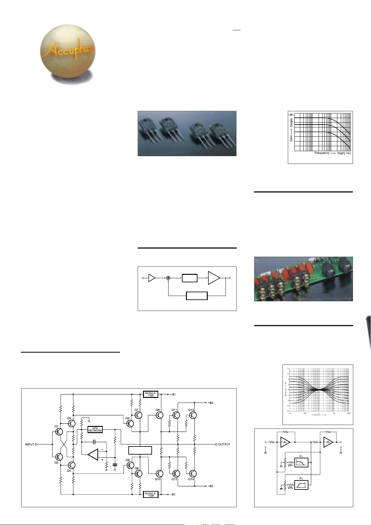
The power transistors used in the output stage
are multi-emitter devices designed for audio
applications, with optimum frequency response, forward-current transfer ratio linear-
High-current power transistors
ity, and switching performance characteristics.
By connecting these devices in a parallel pushpull configuration (Fig. 1), the E-212 achieves
low internal impedance. The transistors are
mounted to large heat sinks for efficient dissipation of thermal energy. This lavish design
results in high-quality power output capabilities rated for 115 watts into 4 ohms, 105 watts
into 6 ohms, or 90 watts into 8 ohms per channel.
Current feedback circuit topology in power
amplifier section assures outstanding
phase performance in high frequency range
In the E-212, signal current rather than voltage is used for feedback. Figure 2 shows the
Current adder
Input
Buffer
Fig. 2 Current feedback amplifier principle diagram
I-V
converter
Trans-impedance
amplifier
Current NFB
network
Amplifier
Output
operating principle of this circuit. At the sensing point of the feedback loop, the impedance
is kept low and current detection is performed.
An impedance-converting amplifier then converts the current into a voltage to be used as
the feedback signal. Since the impedance at
the current feedback point (current adder in
Figure 2) is very low, there is almost no phase
shift. Phase compensation can be kept to a
minimum, resulting in excellent transient response and superb sonic transparency. Fig-
ure 3 shows
frequency
response for
different gain
settings of
the current
feedback
amplifier. The
graphs dem-
Fig. 3 Frequency response with current feedback
(Response remains uniform even when gain changes)
onstrate that
response remains uniform over a wide range.
Highly reliable logic-controlled relays
To realize the shortest possible signal paths,
all switching is performed by logic-controlled
relays arranged in an optimized layout. The
hermetically sealed relays are high-quality
types developed specifically for demanding
communication applications. The contacts are
twin crossbar types plated with gold for minimum contact resistance and outstanding longterm reliability.
Gold-plated input/output
jacks connected directly to relays
Tone controls use summing active filters
for highest sound quality
The tone control circuitry in the E-212 was
specially designed with summing active filters.
Figure 4 illustrates the operation principle of
this circuit. The flat signal is passed straight
through, and only when an adjustment is required, the
characteristics are
created at
F1 and F2
and added
to the signal, thereby
producing
the desired
change.
Tone control characteristics
Bias stabilizing
circuit
Fig. 1 Power amplifier circuit diagram (one channel)
Fig. 4 Tone control circuit diagram
(summing active filter type)
Page 3

This design provides efficient control without
degrading signal purity.
Strong power supply with large power
transformer and high filtering capacity
Two pairs of speaker output terminals
The oversize speaker terminals accept even
very heavy-gauge speaker cable. The A/B
switch-selectable outputs allow driving two
pairs of loudspeakers, while the A+B position
can be used for bi-wiring where the low and
high frequency drivers of a speaker are connected to the amplifier with separate leads.
Analog peak power meters
The large analog power meters use logarithmic compression to cover a wide dynamic
range. The peak hold function lets the user
easily monitor the output level of the rapidly
fluctuating music signal.
The power supply is the source of energy for
an amplifier. The E-212 features a massive
400 VA power transformer and two large electrolytic capacitors rated for 22,000 µF each.
This assures ample reserves also for reproduction of demanding bass passages.
High-capacity power transformer and filtering capacitors
n Power amplifier assem-
bly with parallel pushpull output stage and
current feedback circuitry mounted to large
heat sink
n Supplied remote commander RC-23
Allows volume adjustment and
source switching.
Page 4

Other Features and Functions
n Option board handles direct digital signal
input for high-grade CD reproduction.
n Option board allows analog record repro-
duction.
n High-quality volume control. Supplied re-
mote commander for volume adjustment
and source switching.
n High carbon cast-iron insulator feet for
high sound quality.
n Loudness compensator for enhanced bass
at low listening levels.
Compensator response
Option Boards
Three types of option boards are available for the E-212: the
Digital Input Board DAC-10, the Analog Disc Input Board
AD-9, and the Line Input Board LINE-9. Insert the desired
board in the rear-panel option board slot.
m The DAC-10 cannot be used in the models E-407, E-406V,
E-306V, E-211, C-265.
m The Analog Disc Input Board AD-10 and the Line Input Board
LINE-10 can also be used.
Option board shown in photo is DAC-10
Digital Input Board DAC-10
This board features an MDS (Multiple Delta Sigma)
D/A converter and has inputs for coaxial and
optical fiber connections.
It can accept the digital output signal from components such as a CD player, MD recorder, DAT
recorder, etc. (sampling frequency range 32 - 96
kHz, 24 bits).
Analog Disc Input Board AD-9
This board contains a high-performance, high-gain
phono equalizer.
Internal DIP switches control MM/MC operation, MC input
impedance, and subsonic filter on/off.
Gain: 36 dB
MM
Input impedance: 47 kilohms
Gain: 62 dB
MC
Input impedance: 10/30/100 ohms
(selectable)
Line Input Board LINE-9
This option board provides an additional set of conventional
unbalanced line inputs which can be used to connect a CD
player, tuner, or other component with analog output.
n Front panel
n Rear panel
Option board
expansion slot
★
A INPUT SELECTOR
LINE-BAL LINE CD TUNER OPTION
B Peak Power Meters
(Decibel Scale, direct reading)
C VOLUME Control
D POWER Switch
E SPEAKER Selector
OFF A B A+B
F BASS Control
G TREBLE Control
H TONE Controls ON/OFF Button
I STEREO/MONO Button
Remarks
★
This product is available in versions for 120/230 V AC. Make sure that the voltage
shown on the rear panel matches the AC line voltage in your area.
★
The shape of the AC inlet, and plug of the supplied power cord depends on the voltage
rating and destination country.
J COMPENSATOR Switch
K TAPE RECORDER Selector
REC OFF SOURCE TAPE
L BALANCE Control
M Attenuator Button
N PHONES Jack
O High Level Input Jacks
P PLAY, REC Jacks
Q LINE INPUTS (BALANCED)
R SPEAKERS Terminals (A, B)
S AC Power Supply Connector
GUARANTEED SPECIFICATIONS
[Guaranteed specifications are measured according to EIA standard RS-490.]
m Continuous Average Output Power 115 watts per channel into 4 ohms
(both channels driven, 20 - 20,000 Hz) 105 watts per channel into 6 ohms
m Total Harmonic Distortion 0.04%, with 4 to 16 ohms load
(both channels driven, 20 - 20,000 Hz)
m Intermodulation Distortion 0.01%
m Frequency Response HIGH LEVEL INPUT: 20 - 20,000 Hz +0, - 0.2 dB
m Damping Factor 100 (with 8-ohm load, 50 Hz)
m Input Sensitivity, Input Impedance
Input
HIGH LEVEL INPUT
BALANCED INPUT
m Gain HIGH LEVEL INPUT ➞ OUTPUT: 42 dB
m Tone Controls Turnover frequency and adjustment range
m Loudness Compensation +6 dB (200 Hz) (Volume control setting -30 dB)
m Attenuator -20 dB
m Signal-to-Noise Ratio
Input
HIGH LEVEL INPUT
BALANCED INPUT
m Power Level Meters Logarithmic compression, peak reading meters
m Load Impedance 4 - 16 ohms
m Stereo Headphones Suitable impedance: 8 - 100 ohms
m Power Requirements 120 V/230 V (Voltage as indicated on rear panel)
m Power Consumption 30 watts idle
m Maximum Dimensions Width 475 mm (18-11/16”)
★
m Weight 18.9 kg (41.6 lbs) net
m Supplied Remote Commander RC-23 Remote control principle:Infrared pulse
For rated output For 1 W output (EIA)
90 watts per channel into 8 ohms
(at rated continuous average output)
Sensitivity
213 mV 22.5 mV 20 kΩ
213 mV 22.5 mV 40 kΩ
(UNBALANCED/BALANCED)
BASS: 300 Hz ±10 dB (50 Hz)
TREBLE: 3 kHz ±10 dB (20 kHz)
Input shorted, IHF-A weighting
S/N ratio at rated input
110 dB
92 dB 81 dB
with a dB scale calibrated for an 8-ohm load
AC, 50/60 Hz
220 watts in accordance with IEC-65
Height 150 mm (5-7/8”)
Depth 422 mm (16-5/8”)
23.0 kg (50.7 lbs) in shipping carton
Power supply: 3 V DC (IEC R6 batteries × 2)
Dimensions: 45 (W) × 136 (H) × 18 (D) mm
Weight: 85 g (including batteries)
Input impedance
S/N ratio (EIA)
81 dB
n Supplied accessories: • AC power cord
• Specifications and design subject to change without notice for improvements.
• Remote commander RC-23
K015Y PRINTED IN JAPAN 850-0121-00 (AD1)http://www.accuphase.com/
 Loading...