

Page 1
PRECISION COMPACT DISC PLAYER
DP-75V
m Separate CD transport and processor sections m MDS type D/A
converter assures phenomenal conversion precision
m Compatib le with next-generation digital sources m Ultra jitter-free
PLL circuit topology m Two sets of digital inputs and outputs m Option
board slots allow adding digital input and output boards m Fully digital
control of CD mechanism m Balanced actuator drive circuitry
Page 2
A new-generation CD player that reproduces even the most subtle musical
details Revolutionary MDS (Multiple Delta Sigma) converter with 24-bit
ultra high precision. Separate CD transport and processor sections. Ready
for handling input from new-generation digital sources such as SACD and
DVD-Audio. Fully digital control of CD mechanism.
The DP-75V incorporates the latest advances
in digital technology . Processing performance
was upgraded to handle the new generation
of super high resolution audio sources such
as SACD and DVD-Audio. Enhanced sound
quality is also available with existing CDs.
Although the DP-75V may look like a
conventional integrated Compact Disc play er,
it really consists of a separate transport
section and a digital processor each of which
can be used on its own.
The processor features a revolutionary MDS
(Multiple Delta Sigma) converter with superb
24-bit precision. This ensures ultra low
distortion and outstanding signal-to-noise
ratio. All other perf ormance aspects have also
been significantly improved. Digital inputs
allow the routing of external digital sources
through the
converter of the
DP-75V, for
playback of any
format source
with exceptional sound quality. To ensure
future upgradability , the unit has option board
slots that support the ADB 2 (Accuphase
Digital Bus 2) interface which accommodates
next-generation formats such as SACD and
DVD-Audio. The EXT DSP option board slot
allows connection of the DG-28 Digital
Equalizer for sound field compensation in the
digital domain.
The simple, refined design of the DP-75V
complements its technological prowess. The
overall result is music reproduction of such
clarity and detail definition that you will
discover a whole new dimension of enjoyment
even in long-familiar CDs.
Coax
Digital
Inputs
Digital
Outputs
Option
Slot 1
Option
Slot 2
Option
Slot 3
External
DSP
Option
(
DIO-OC1
RX
Opto
RX
Coax
RX
Opto
RX
Coax
Opto
RX
Coax
)
Opto
RX
DP-75V
CD Transport
Section
DAI
Decoder
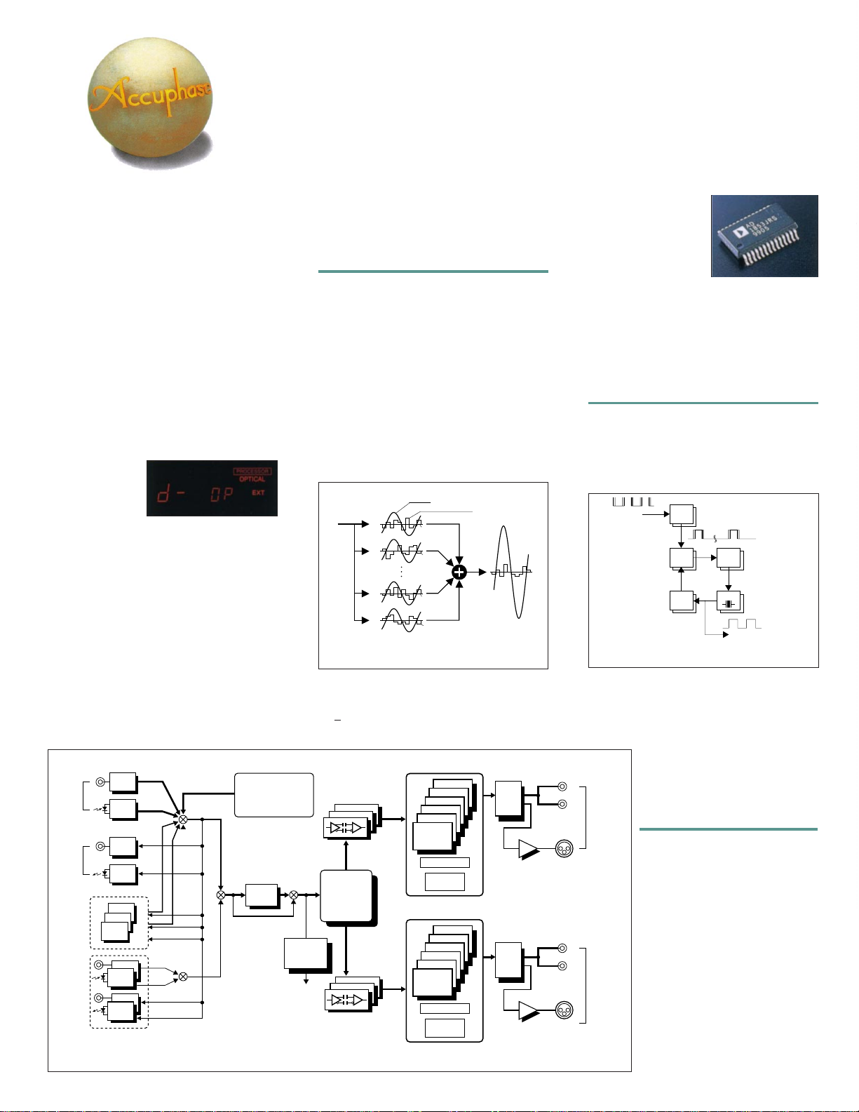
Fig. 1 Block diagram of DP-75V processor
[Digital Processor Section]
Innovative MDS (Multiple Delta Sigma)
converter reduces distortion to theoretical
limits and assures outstanding S/N ratio
The output signal is generated by a newly
developed D/A converter
that provides
excellent performance and sound quality . The
MDS (Multiple Delta Sigma) principle employs
several delta sigma type converters in a
configuration, resulting in a dramatic
parallel
enhancement of precision.
The delta sigma
principle combines oversampling with noiseshaping (a kind of digital feedback) to project
the amplitude information of the digital signal
onto a time axis for precise conversion. Figure
2 shows several delta sigma converters that
are fed the same signal and whose outputs
are combined to arrive at the overall wav eform.
Signal
Conversion error
1
S
e
1
S
2
e
2
Sn-
1
en-
1
S
n
e
n
Digital
input
DAC
#1
#2
#1
n
#
Fig. 2 MDS type D/A converter principle
In the DP-75V six delta sigma converters are
operated in parallel, resulting in a
performance improvement by a f actor of 2.45
(=√6). An important charac-teristic of the MDS
MDS 24bit
D/A Converter ×6
Digital
Isolator
∆Σ
Digital Filter
Output
Level
MDS 24bit
D/A Converter ×6
∆Σ
Digital Filter
Output
Level
Ultra
Jitter Free
PLL
Master
Clock
Format
Converter
Digital
Isolator
3 Pole
Linear
Phase
Low Pass
Filter
3 Pole
Linear
Phase
Low Pass
Filter
MDS
output
S
e
Balanced
Buffer
Balanced
Buffer
0
0
principle is that the
performance benefits
are achieved
regardless of signal
frequency and signal
level. Thus noise at
very low signal levels, that was difficult to
contain with conventional delta sigma
converters, can now be drastically reduced.
The audible result is music reproduction
emerging from complete silence with an
impressive sense of clarity and nuance.
Ultra jitter-free PLL circuit
For synchronizing the operation of the D/A
converter with the digital audio interface (DAI),
a phase-locked loop (PLL) circuit is used
which generates a master clock to be used
as a system reference. As shown in Figure 3,
DAI input signal
Preamble
Preamble signal
detector
(pulse distortion removed)
Phase
comparator
Frequency
divider
Loop
filter
VCO
Fig. 3 Ultra jitter-free PLL cir cuit
the Ultra Jitter-Free PLL Circuit of the DP-75V
consists of a preamble detector and a voltagecontrolled oscillator (VCO) using a quartz
crystal element. The master clock produced
by this PLL circuit is free from the
effects of pulse distortion and jitter.
Unbalanced
Outputs
1
2
Left
Analog
Outputs
Separate processor section with
coaxial and optical input for
digital signals
A digital input allows the user to
Balanced
Output
enjoy the top-level performance of
the processor section with other
components that can supply a
digital signal. In addition, a digital
output lets the user connect a DAT
Unbalanced
Outputs
Balanced
Output
1
2
Right
Analog
Outputs
recorder, MiniDisc recorder, or
other component capable of
recording a digital signal, so the
output of the CD transport or the
signal from connected external
sources can be recorded. A direct
connection from
of the CD transport section
Digital Preamplifier DC-330 is also
possible.
Master clock output
(free from jitter and
pulse distortion)
the digital output
to the
Page 3

n Supplied remote
commander RC-25
Serves for input
selection, direct play,
repeat and program
play, level
adjustment and
other functions.
Linear phase analog filters
provide superior characteristics
Aliasing noise in the extreme upper frequency
range is removed by a 3-pole linear phase
type filter with outstanding phase
characteristics. The cutoff frequency is
designed to minimize phase shift within the
passband. Strict selection of all filter
components assures sonic purity and musical
accuracy .
Digital level control prevents sound quality
deterioration
The 24-bit MDS D/A converter in the DP-75V
is not subject to
the deterioration of resolution
and allows precise level attenuation down to
–60 dB.
D/A converter with printed circuit boards
made from Teflon (glass fluor ocarbon resin)
with low dielectric constant and low loss
The D/A converter boards use a substrate of
glass fluorocarbon resin which has a stable,
low dielectric constant as well as superior heat
resistance and high-frequency characteristics.
Using this material for the audio circuitry
assures signal transmission with
the highest
purity, resulting in a clear improvement in
perceived signal-to-noise ratio. In the DP-75V,
gold-plated copper traces further contribute
to sonic purity.
* Teflon is a registered trademark of DuPont USA.
Fully balanced analog output circuitry
The audio output section features balanced
circuitry which is isolated from the ground line.
T o match any system configuration both a set
of balanced XLR connectors and a set of RCA
type unbalanced connectors are provided.
[CD T ransport Section]
Fully digital control of CD mechanism
The control circuitry of the mechanism section
is fully digital, allowing the use of adaptive
filters to optimize servo performance for each
individual disc. This assures enhanced
operation stability and a drastic reduction in
error rate.
Laser pickup with integrated RF amplifier
for error-free operation
The pickup used in the DP-75V employs an
RF amplifier which is so compact that it can
be directly integrated in the photo detector
pickup assembly. This assures that the highlevel output signal remains free from noise
interference, which in turn reduces the error
rate.
n Assembly with DAI
encoder/decoder, ultra
jitter-free PLL circuit, and
other digital processing
circuits. Two MDS D/A
converter boards (one each
for right and left) use Teflon
with a low dielectric constant
and low loss. The analog output
connector assembly is also visible.
Balanced drive circuitry for CD actuators
The motors and actuators that move the disc
tray, spindle, sled, and the focusing and
tracking assembly are driven b y two amplifiers
arranged in a balanced configuration.
Because there is no current flowing in the
ground line, the operation of other circuits in
the player remains entirely unaffected.
Tray lock prevents resonance
Power -on play and frame display capability
(1 frame = 1/75 second)
Page 4

Option Boards
Three option board slots provide fle xibility
for input and recording output configurations
In addition to the standard digital inputs and
outputs, the option board slots provide
additional ways to utilize the high perf ormance
of the digital processor section of the DP-75V .
To assure compatibility with the next
generation of source formats, such as SACD
and DVD-A udio, the option board slots support
the ADB2 interface standard.
l A digital input/output board with optical and
coaxial connectors (DIO-OC1) can be used.
BNC, HC optical (ST), and HPC balanced
input is also possible.
l An HS (High Speed) Link option board can
be installed for connection of the SACD
transport DP-100.
l The EXT DSP option board slot allows
connection of the DG-28 Digital Equalizer .
The ADB 2: Accuphase Digital Bus 2
Interface standard for Accuphase option
boards supporting sampling rates above
48 kHz, such as those used by SACD and
DVD-A udio .
n FRONT PANEL
AB CD E
FG
[Guaranteed specifications are measured according to the EIAJ standard CP-2402.
Measurement disc: CP-2403]
[CD Transport]
l Format Quantization: 16 bits
Standard CD format
l Data read principle Non-contact optical pickup (semiconductor laser)
l Laser type GaAlAs (double heterodyne diode)
[Digital Processor]
HIJL
K
l Input format Quantization: 16 - 24 bits, linear
EIAJ CP-1201 compatible
n REAR PANEL
Option board slots
EXT DSP slot (for connection to DG-28)
M
NO P
A Play track indicator
B TRACK/INDEX indicator
C TIME indicator
D Output level/frame indicator
E Disc tray OPEN/CLOSE button
F CD transport/processor selector button
G External digital component ON/OFF button
H POWER switch
I Disc tray
J PLAY/PAUSE button
Remarks
H
This product is available in versions for 120/230 V AC. Make sure that the voltage shown on the rear panel matches the AC line voltage in your area.
H
The shape of the AC inlet and plug of the supplied power cord depends on the voltage rating and destination country.
n Supplied accessories l AC power cord
l A udio cable with RCA plugs
l Remote Commander RC-25
K T rack search buttons
(Processor operation: external input
selector buttons)
L STOP button
M Analog outputs
2 sets of unbalanced connectors, 1 set of
balanced connectors
N Digital inputs (coaxial, optical)
O Digital outputs (coaxial, optical)
P AC inlet (for supplied power cord)
H
l Digital input Format: Digital audio interface
ormat and level
(EIAJ CP-1201)
l Digital output Format: Digital audio interface
format and level
(EIAJ CP-1201)
l Frequency response 0.5 to 50,000 Hz +0, –3 dB
l D/A converter MDS type, 24 bits
l Total harmonic distortion 0.0008% (20 - 20,000 Hz)
l Signal-to-noise ratio 116 dB
l Dynamic range 112 dB (24-bit input; LPF OFF)
l Channel separation 108 dB
l Output voltage and BALANCED: 2.5 V into 50 ohms, balanced XLR type
impedance
l Output level control 0 to –60 dB in 1-dB steps (digital)
l Power requirements 120V/230V
l Power consumption 26 W
l Dimensions Width 475 mm (18-11/16” )
l Weight 19.8 kg (43.7 lbs) net
l Supplied Remote Remote control principle: infrared pulse
Commander RC-25
l Any option board can be used in any slot.
l All option boards designed for the DC-330, DC-300,
DG-28, DP-65V , DP-75V, and DF-35 can be used.
HPC Coaxial Input Board DI-BNC1
uses 75-ohm coaxial cable with BNC plug.
Digital Input/Output Board DIO-OC1
provides two sets of coaxial and optical connectors, for
input and output of digital signals.
HPC Optical Input/Output Board DIO-ST1
serves for connection of an HPC optical fiber link
corresponding to the ST standard.
✽ ST is a registered trademark of AT&T.
✽ HPC optical fiber cables (HLG-10, etc.) are availab le
from Accuphase.
AES/EBU Input/Output Board DIO-PRO1
provides a set of XLR input and output connectors
conforming to AES/EBU professional digital standards.
✽ HPC balanced cables (HLC-10, etc.) are available
from Accuphase.
✽ A digital input board can act as an additional input
for the processor section.
✽ A digital output board can act as an additional output
for the CD transport section or external components
connected to the unit.
DP-75V Guaranteed Specifications
Sampling frequency: 44.1 kHz
Error correction principle: CIRC
Number of channels: 2
Revolution speed: 500 - 200 rpm
Scan velocity: 1.2 - 1.4 m/s, constant
Sampling frequency (automatic detection):
32 kHz, 44.1 kHz, 48 kHz 88.2 kHz, 96 kHz
176.4 kHz, 192 kHz, 2.8224 MHz
(implemented through option board)
OPTICAL: Input –27 to –15 dBm
COAXIAL: 0.5 Vp-p, 75 ohms
OPTICAL: Output –21 to –15 dBm
COAXIAL: 0.5 Vp-p, 75 ohms
UNBALANCED: 2.5 V into 50 ohms, RCA-type phono jack
(Voltage as indicated on rear panel)
Height 150 mm (5-7/8” )
Depth 397 mm (15-5/8”)
25.0 kg (55.1 lbs) in shipping carton
Power requirements: 3 V DC, IEC R4 (size AAA) batteries × 2
Dimensions: 66 (W) × 175 (H) × 20 (D) mm
Weight: 225 g (including batteries)
(constant linear velocity)
Wavelength 660 nm
AC, 50/60 Hz
m Specifications and design subject to change without notice for improvements.
PRINTED IN JAPAN L9910 851-0165-00 (AD1)
 Loading...