

Page 1
●Channel divider units with high-speed DSP for fully digital signal processing
●Standard configuration allows 4 -channel (4-way) system setup ● 59
selectable cutoff frequency points ●Highly accurate 96 dB/oct attenuation slope
●Time alignment function allows delay time setting in 0.5-cm steps ● Delay
compensator offsets signal delays in filter circuitry ● Further refined MDS++
D/A converter ● Output mode can be set to monophonic specifications
Page 2
Multi-channel divider with fully digital signal processing – High-speed 40-bit floating
point DSP provides the processing power for four channel units supplied in standard
configuration. Highly accurate digital filters offer a choice of 59 cutoff frequency
points and up to 96 dB/octave attenuation. Integrated time alignment function
adjustable in 0.5-cm steps, and delay compensator for automatically offsetting any
filter circuit delays. Output mode can be changed to monophonic specifications.
Multi-amplification is regarded as the pinnacle of the
audio world. The term refers to dividing the musical
spectrum into several distinct bands and handling
each of these using a dedicated power amplifier and
directly connected speaker unit. Such a system is
necessarily more complex, but when configured and
adjusted properly, it can achieve sound reproduction
on a scale that is not possible by any other means.
Sonic definition and sound quality can be optimized
by the user to obtain exactly the desired result.
Configuring a multi-amplified system affords truly
one of the greatest pleasures of audio.
The Digital Frequency Dividing Network DF-55
represents a full model change of the model DF-45.
A high-speed, high-precision DSP further minimizes
any calculation errors,
implementing accurate
filtering of the highest
order. Each bandwidth
is handled by a
dedicated divider unit,
and a full array of
functions including
High-speed 40-bit floating point
Digital Signal Processor (DSP)
frequency dividing filters (low-pass, band-pass,
high-pass) with 96 dB/octave attenuation, delay and
delay compensation, level control, and phase
switching are implemented in the digital domain.
Digital as well as analog line and balanced inputs
are provided, and the unit comes as a 4-channel
device (for 4-way amplification) in its standard
configuration.
High-speed, high-precision DSP
implements fully digital signal processing
The DF-55 features high-speed digital signal
processing with amazing power. Latest digital
circuit topology and advanced technology
come together in a filtering DSP that has a
32-bit mantissa and 8-bit exponent section.
The floating point principle enhances
calculation accuracy by dividing numeric
values into mantissa and exponent, thereby
preventing errors even when handling very
small values. This results in dramatically
improved dynamic range and superior
precision, allowing very steep cutoff slope
settings of 48 dB or 96 dB per octave.
Assembly with
high-speed DSP chip
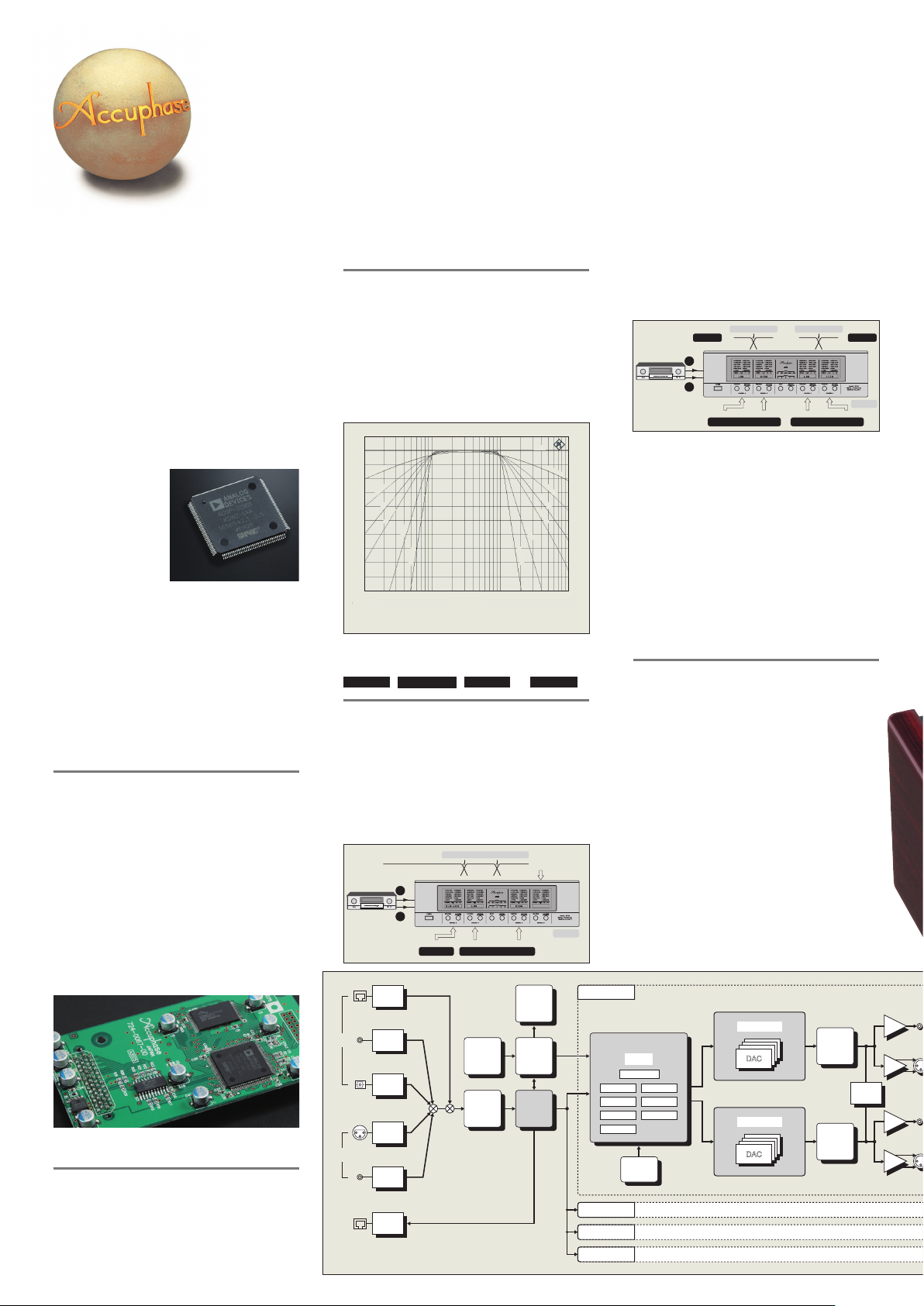
59 selectable cutoff frequency points
Filter frequency points can be set over the range
from 31.5 Hz to 22.4 kHz in 1/6-octave intervals. In
addition, 10, 20, and 290 Hz points are also
provided, resulting in a total of 59 points. Each
divider unit is fully flexible and allows free selection
of the lower and upper cutoff frequency.
Six filter slope characteristics up to 96 dB
per octave
The filter attenuation characteristics can be set to
6 dB, 12 dB, 18 dB, 24 dB, 48 dB, or 96 dB per
octave. The 96 dB/octave setting in particular
allows the driver unit to reproduce only its
intended frequency without being affected by
adjacent frequency bands. This makes it possible
to create a multi-amped system that takes
musical accuracy to an unprecedented level.
〔dBr〕
PASS
0
−
10
6dB/oct
−
20
−
30
12dB/oct
−
40
18dB/oct
−
50
24dB/oct
−
60
−
−
−
−
100
[Cutoff frequency setting 100 Hz for lower and 1 kHz for upper range]
48dB/oct
70
80
90
10 20 30 50 70 100 200 500 1k 2k 3k 5k 7k 10k
96dB/oct
Frequency
Fig. 1 Divider Unit Slope Characteristics (Bandpass Filter)
96dB/oct
48dB/oct
PASS
12dB/oct
18dB/oct
24dB/oct
6dB/oct
(Hz)
Output mode of each divider unit can be set to
STEREO, MONO L+R
, MONO L ,
MONO R
or
In normal use, the divider units will be set to
the STEREO position, but by changing the
setting to monophonic (MONO) operation, the
left-channel and right-channel DAC outputs
within the unit are added up, resulting in a
parallel drive configuration that further
reduces residual noise.
❶Use for a subwoofer (3D) system
In 3-way system,
channel D is set to
OFF
Display
Micro-
Computer
Date/Clock
Distributor
DF-55
Ultra-low range (monophonic)
L
Preamplifier
R
HS-Link
HS-Link
Receiver
Coaxial
Digital
Inputs
Analog
Inputs
Digital
Output
Optical
Balanced
Line
Hs-Link
Coaxial
Receiver
Optical
Receiver
A/D
Converter
A/D
Converter
Hs-Link
Transceiver
Fig. 2 DF-55 Block Diagram
Cutoff frequency
Low range High range
Channel A Channel B Channel C
MONO L+R
Encoder
DAI
Decoder
STEREO
In this example, the left and right signals in the ultra-low
frequency range are mixed (channel A output mode is
set to "MONO L+R" position), for configuring a
three-way system with a subwoofer.
❷
2-way system for left and right 2-way monophonic setup
Preamplifier
Two of the four divider units in the DF-55 are
set to the "MONO L" position and the other
two units to the "MONO R" position. This
allows setting up a 2-way monophonic spec
system.
❸
2-way to 4-way system, using two DF-55 units
The divider units of one DF-55 are set to the "MONO
L" position, and the units of the other DF-55 to the
"MONO R" position. This allows setting up a 2-way
to 4-way monophonic spec multi-amped system.
Time alignment function allows delay
adjustment in 0.5-cm steps
The sound emanating from a speaker travels through the
air at a speed of about 343.5 meters per second (when
the ambient temperature is 20 degrees centigrade).
Compared to the propagation speed of light or of electrical
signals, this is extremely slow. When multiple speaker
units are used, necessarily located at different positions,
there will be differences in the time required for the sound
to reach the ear of the listener. In a multi-speaker system,
each sound source position, namely the position of the
diaphragm in the respective driver unit, is not aligned on
the front/back plane, also leading to different arrival times
of the sound. Compensating for such differences is called
time alignment (see Figure 3).The DF-55 incorporates
a DELAY function that uses digital signal processing to
electrically adjust the time when the sound from each
driver reaches the listener. Normally, a delay would be
expressed as a time value, but since the delay here is
caused by spatial distance, the DF-55 converts the delay
into a distance value (cm) for easier understanding.
Channel A
DSP:Digital Signal Processor
Floating Point
DSP
Master Level
Frequency
Channel B
Channel C
Channel D
Level
Phase Slope
Delay Delay Comp
Output
Coefficient
Memory
Cutoff frequency
Forleftchannel
Low range Low range
L
R
Channel A
MONO L
D/A Conversion System×4
D/A Conversion System×4
Cutoff frequency
High range High range
Channel B Channel D
Channel C
MONO R
++
MDS
Digital Filter
DAC
++
MDS
Digital Filter
DAC
Same as Channel A
Same as Channel A
Same as Channel A
Analog
Attenuator
ON/OFF
Analog
Attenuator
ON/OFF
Forrightchannel
DF-55
Mono
ON/OFF
Buffer
Buffer
Buffer
Buffer
Line
Balanced
Line
Balanced
Page 3

Left
Analog
Outputs
Right
Analog
Outputs
Fig. 3 Time Alignment Principle
◆
The DF-55 comes standard with four units named CHANNEL A - D
(4-way configuration). The assembly shown here carries the
coaxial digital input and output connectors, line/analog input
conne ctors, MDS++ D/A converter modules for
4 channels, and line/analog output
connectors.
Block diagram ofMDS++ converter
I/V
I/V
−
+
DAC output
Subtraction
(Normal phase output)
(Reverse phase output)
Current summing Voltage summing
I(current)/V(voltage)
converter
DAC1
DAC2
DAC3
DAC4
I/V
I/V
t secondsd cm
t seconds
Input
L
L
H
Delay
Delay
Time
Start time
Delay ensures that
○
and
○
signals
arrive at the ear at the same time
L
H
Speaker unit
○
and
○
sound source
(diaphragm) are d centimeters apart
L
H
Delay function
delays ○waveform
by t seconds
H
H
H
H
H
L
e
<Time alignment using delay>
Speed of sound = 331.5 + 0.607 T [m/sec] T: temperature (°C)
Consequently, at 20°C, sound travels at about 343.5 m/sec.
In the example above, when DELAY function for
○
is set to d cm, the
signal start for
○
will be delayed by t = d/34,350 seconds, causing the
sound from ○ and ○ to reach the listener at the same time.
Other Functions and Features
High-performance HyperstreamTM DAC used for MDS++
MDS (Multiple Delta Sigma) is a revolutionary design which
employs several delta sigma type converters in a parallel
configuration. In the combined output of these multiple
converters, the ratio of conversion errors to the audio signal
becomes larger, resulting in a drastic improvement in all
relevant aspects of converter performance, such as accuracy,
S/N ratio, dynamic range, linearity, and THD. (When the
number of converters is taken as "n", the improvement is n.)
Because the performance improvement afforded by the MDS
principle is not dependent on signal frequency or signal level,
noise at very low levels that
plagues the output of
conventional converters can
also be reliably reduced.
In the DF-55, four Hyperstream
TM
DAC chips (ES9008 made by
ESS Technology) of the latest
generation are driven in parallel. Compared to a single
converter, this results in an overall performance improvement
by a factor of 2 (= 4). As shown in the diagram, the MDS++
circuit features an enhanced current-to-voltage (I/V) converter
for processing the D/A converter output current. A combination
of current summing and voltage summing is used, for optimized
operation.
The overall result is improved stability and top-notch
performance. The music emerges from a totally silent
background, with breathtaking detail resolution and accurate
spatial information.
■
Digitalattenuatorwithsettingrangefrom-40.0dBto+12.0dB(in0.1-dBsteps)allows
preciseleveladjustmentsforleftandrightchannels.
■"Analog ATT" function can be activated for specific channels to reduce residual noise when
using high-efficiency midrange or high range speaker units (ON: -10 dB).
■Versatile choice of input connectors. Digital signals can be supplied via coaxial, optical,
and HS-Link inputs. Line and balanced inputs are available for analog signals.
■"Full Level Output Protection" function safeguards the speakers if a digital signal
without volume control data is input (Output level reduction -40 dB).
■Unused divider units can be set to OFF (all display elements and LED
indicators are out).
■Safety Lock prevents inadvertently changing any settings.
■Display indication can show predefined strings or custom strings
entered by the user (max. 8 characters, character set 97
characters).
■Independent phase switching for left and
right channel (4 patterns).
Page 4

Delay compensator function of DF-55 (providing automatic compensation for signal delays)
Besides delays caused by speaker placement,
a certain delay will also occur when a signal
passes through a filter circuit. The DF-55
incorporates a function called "DELAY COMP"
that compensates for such delays. As an
example, the illustration at right shows a
simplified representation of how the delay
compensator function works in a 3-way system.
■Regardless of whether a circuit is analog or
digital, when the signal has to pass through a
filter, the output will be delayed by a certain
amount, causing a delay in step response
and impulse response.
■Generally, a low-pass filter will have more
delay. The DF-55 therefore only provides
compensation when low-pass filtering is
used.
■The lower the filter frequency and the steeper
the filter slope, the longer the delay.
The DF-55 calculates and displays the
ON
theoretical delay time, and automatically
provides compensation. (Default setting)
OFF
The DF-55 calculates and displays the
theoretical delay time for reference, and the
user can manually set any desired value.
<Operation principle of delay compensator>
DELAY COMP
function
ON/OFF
ON/OFF
ON/OFF
When DELAY COMP is OFF, the output
signals in each channel will be shifted,
causing time misalignment. Output
signal vs input signal time lag (delay)
Output○
Output○
Output
Input
As shown above, the signal
will be delayed by a different
duration when passing
through different filter circuits.
〔Channel A〕
Delay: t3 s
(Low-pass filter)
〔Channel B〕
Delay: t2 s
(Band-pass filter)
〔Channel C〕
Delay: 0 s
(High-pass filter)
Time lag (delay) of output signal with
regard to input in each channel
When OFF:
a
is slowest, delayed
○
by t3 seconds versus ○
a
OFF ON
b
○
is delayed
by t2 seconds
versus
b
OFF ON
〔When ON: Delayed by t3 seconds〕
c
○
When ON:
Delayed by
c
○
t3 - t2 seconds
t
2
t3−t
t
3
When DELAY COMP is
ON, the time differ ence
between output signals ○,
c
b
○, and ○iseliminated.
ON or OFF
c
2
When DELAY COMP is ON
c
b
○
and
○
are delayed, using
a
slowest ○as reference ○
(
0
○
〔Channel A〕
b
○
is delayed by [t3 - t2] seconds
(
t3−t
2
○
〔Channel B〕
c
○is delayed by t3 seconds
(
t3
○
〔Channel C〕
Actual dela y compe nsator
indication is in cm, converted
a
from the above compensation
time value.
0
a
compensation time)
compensation time)
b
c
compensation time)
■DF-55 default settings and display indication
Function Display indication
機 能
LOWER FREQUENCY
LOWER SLOPE
LEFT LEVEL
LEFT DELAY(cm)
DELAY COMP
OUTPUT
STEREO
* ( )
symbol at top right of level indication is shown when "Full Level Output Protection" function is set to ON.
UPPER FREQUENCY
UPPER SLOPE
RIGHT LEVEL
RIGHT DELAY(cm)
PHASE
ASSIGNMENT
ディスプレイ
Cutoff frequency settings (Hz)
10 20 31.5 35.5 40 45 50 56 63 71 80 90
100 112 125 140 160 180 200 224 250 280 290 315
355 400 500 560 630 710 800 900 1000 1120 1250 1400
1600 1800 2000 2240 2500 2800 3150 3550 4000 5000 5600 6300
7100 8000 9000 10k 11.2k 12.5k 14k 16k 18k 20k 22.4k
DF-55 Guaranteed Specifications
[Guaranteed specifications measured in compliance with JEITA standard method CP-2402A]
●Digital inputs
COAXIAL Format: IEC 60958/AES3 compliant
Sampling frequencies 32 kHz to 192 kHz (16 - 24 bit 2-channel PCM)
OPTICAL Format: JEITA CP-1212
Sampling frequencies 32 kHz to 96 kHz (16 - 24 bit 2-channel PCM)
HS-LINK Connector: RJ-45, HS-Link cable
Sampling frequencies 32 kHz to 192 kHz (24 bit 2-channel PCM)
●Analog inputs Maximum input level 3.7 V (1 kHz, 2.5 V output)
A/D converter Principle: 1-bit delta sigma modulation
Sampling frequency: 176.4 kHz
■Front panel
Divider units
Channel A Channel B Channel C Channel D
Quantization: 24 bit
●Digital outputs HS-LINK Connector: RJ-45, HS-Link cable
COAXIAL Format: IEC 60958
●Frequency response HS-Link 2.0 - 50,000 Hz +0 -3 dB
●D/A converter Quantization: 24 bit
STEREO operation: 4MDS++ type
MONO operation: 8MDS++ type
●THD 0.001% (20 - 20,000 Hz)
q w e
ytr
●S/N ratio
COAXIAL/OPTICAL
HS-LINK
■Rear panel
iu o
Analog outputs
(LINE/BALANCED)
Channel DChannel CChannel BChannel
A
●Dynamic range "Analog ATT" OFF: 117 dB, "Analog ATT" ON: 114 dB
●Channel separation 108 dB (20 - 20,000 Hz)
Analog input
●Slope characteristics 6 dB/octave, 12 dB/octave, 18 dB/octave
24 dB/octave, 48 dB/octave, 96 dB/octave
* When cutoff frequency is 10 Hz: 48 dB/octave, 96 dB/octave not available
20 Hz: 96 dB/octave not available
●Delay setting range
(converted into distance)
-3,000 to +3,000 cm (0.5-cm steps)
●Level adjustment range "Analog ATT" OFF: -40 to +12.0 dB (0.1-dB steps)
"Analog ATT" ON: -50 to +2.0 dB (0.1-dB steps)
★
!0
q POWER switch
w FUNCTION knob (To select a function)
e ENCODER knob (To set the value)
r Input selector
t Memory selector
y Display
INPUT: BAL, LINE, HS-LINK, COAX, OPTO
MEMORY: 1, 2, 3, 4, 5
Remarks
★This product is available in versions for 120/230 V AC. Make sure that the voltage shown on the rear panel matches the AC line voltage in your area.
★The shape of the AC inlet and plug of the supplied power cord depends on the voltage rating and destination country.
■
Supplied accessory
●
C power cord
A
u Digital inputs
HS-LINK,COAXIAL,OPTICAL
i Digital output
HS-LINK
o Analog inputs
LINE, BALANCED
!0 AC power connector
★
(for supplied power cord)
●Output voltage/output LINE: 2.5 V, 50 ohms, RCA-type phono connector
impedance BALANCED: 2.5 V, 50 ohms, balanced XLR connector
●Minimum loadimpedance
●Power requirements
LINE/BALANCED 600 ohms
AC 120 V/230 V, 50/60 Hz (Voltage as indicated on rear panel)
●Power consumption 29 watts
●Max. dimensions Width 465 mm (18-5/16")
Height 151 mm (5-15/16")
Depth 396 mm (15-9/16")
●Mass 14.7 kg (32.4 lbs) net
20.0 kg (44.1 lbs) in shipping carton
(Cutoff characteristics: -3.0 dB, 59 points)
STEREO operation
120 dB
120 dB
113 dB
MONO operation
122 dB
122 dB
114 dB
●
Specifications and design subject to change without notice for improvements.
A1105Y PRINTED IN JAPAN 851-0202-00(B1)
 Loading...