

Page 1
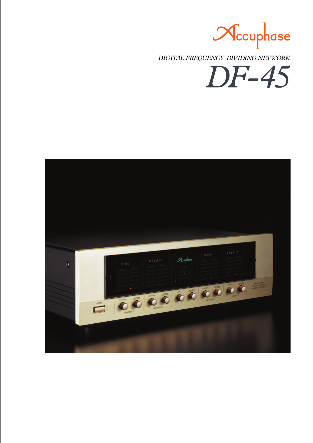
m Channel divider units with high-speed DSP for fully digital signal
processing m Equipped for 4-channel (4-way) system configuration m 59
selectable cutoff frequency points m Highly accurate 96 dB/oct attenuation
slope m Time alignment function allows delay time setting in 1-cm steps
m Delay compensator offsets signal delays in filter circuitry m Further refined
MDS++ D/A converter m Digital input possible in conjunction with DC-330
Page 2
Multi-channel divider with fully digital signal processing – High-speed 40-bit floating
point DSP provides the processing power for four channel units supplied in standard
configuration. Choice of 59 cutoff frequency points ensures total flexibility. Highly
accurate digital filters enable 96 dB/octave slope characteristics. Time alignment
function adjustable in 1-cm steps, plus delay compensator for offsetting filter circuit
delays ensure superb spatial accuracy. HS-Link capability provides SA-CD support.
Multi-amplification is regarded as the pinnacle of the
audio world. The term refers to dividing the musical
spectrum into several distinct bands and handling each
of these using a dedicated power amplifier and directly
connected speaker unit. When configured and adjusted
properly, such a system can achieve sound
reproduction on a scale that is not possible by any
other means. Sonic definition and spatial imaging can
be optimized by the user to obtain exactly the desired
result. Configuring a multi-amplified system affords truly
one of the greatest pleasures of audio.
The Digital Frequency Dividing Network DF-45 represents a further evolution
of the model DF-35.
Only the latest digital
technology is employed
throughout, and all internal signal processing
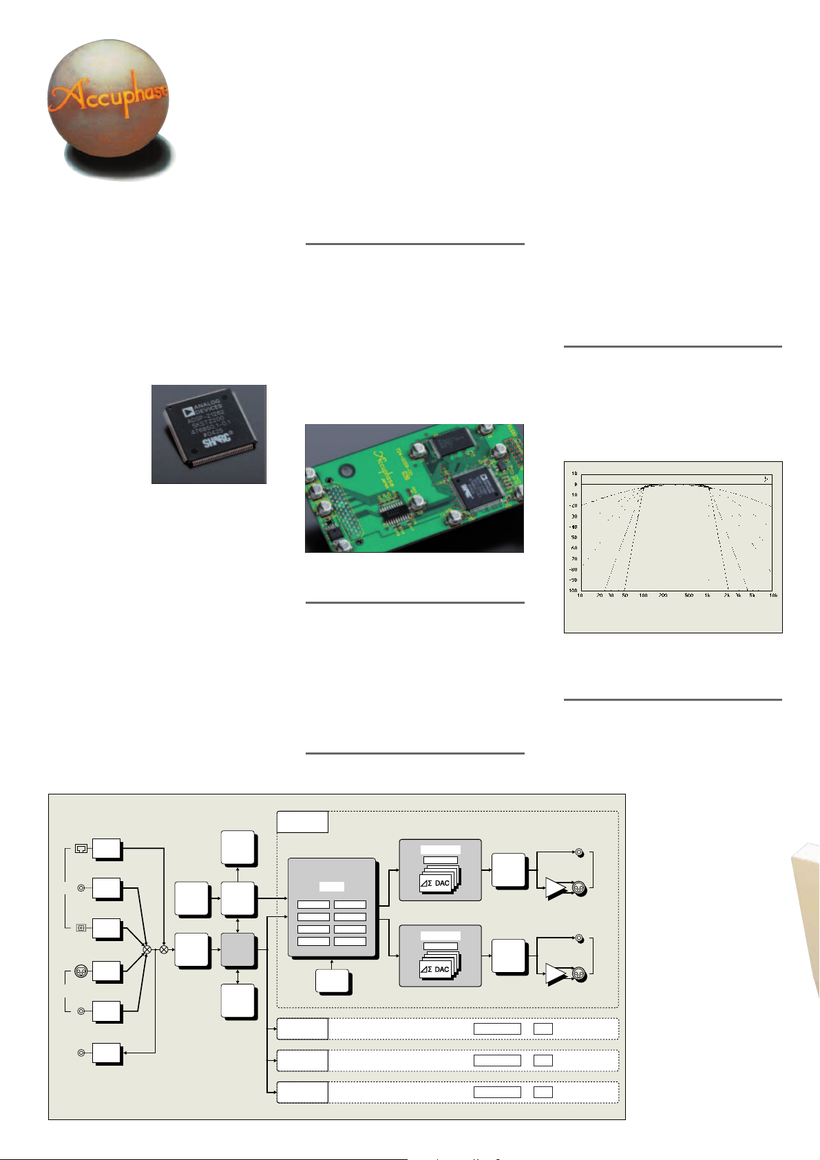
occurs fully in the digital
domain. High-speed 40bit floating point DSP
High-speed 40-bit floating point
Digital Signal Processor (DSP)
chips allow super-precise high-order filtering with a
slope of 96 dB/octave. This in turn enables the digital
input to handle sources up to SA-CD quality. In addition, balanced and unbalanced analog inputs are also
provided, and the unit comes as a 4-channel device
(for 4-way amplification) in its standard configuration.
Each channel in the DF-45 is handled by a dedicated
unit. A full array of functions including frequency dividing
filters (low-pass, band-pass, high-pass), attenuation
slope characteristics, delay and delay compensator
function, level control, and phase switching are
implemented in the digital domain. To store parameter
settings for various scenarios, five memory positions
are provided.
The DF-45 allows the user to select cutoff frequency
settings for adjacent bands from 59 choices, plus six
different attenuation slope settings (max. 96 dB/oct).
This unprecedented flexibility makes it possible to elicit
optimum performance from every speaker unit,
achieving a smooth transition between bands and
ensuring exactly the desired overall energy balance. A
high-quality multi-amp system built with the DF-45 will
sound its very best.
HS-Link
Digital
Inputs
Analog
Inputs
Digital
Output
HS-Link
Receiver
Coaxial
Coaxial
Receiver
Optical
Optical
Receiver
Balanced
A/D
Converter
A/D
Converter
Unbalanced
Coaxial
Coaxial
Transceiver
Fig. 1 DF-45 Block Diagram
Encoder
DAI
Decoder
Display
Micro-
computer
Clock
Distributor
Sampling
Rate
Converter
Channel dividers based on fully digital signal
processing
The central task of a multi-amp system is of
course the division of the frequency spectrum into
multiple bands or channels. The channel dividers
in the DF-45 feature an impressive array of
sophisticated digital technology based on a DSP
chip with amazing power. The high-speed 40-bit
floating point design of this device makes it
possible to implement all filtering and delay
functions as well as phase and level control in
fully digital form. With minimal temperature drift
and excellent long-term stability, this ensures
filtering performance of the highest order.
Circuit assembly
with high-speed DSP
High-speed 40-bit floating point DSP assures
precision digital filtering
As a crucial circuit element, the digital filter is
configured with a high-speed 40-bit DSP that has
a 32-bit mantissa and 8-bit exponent section. The
floating point principle enhances calculation
accuracy and results in dramatically improved
dynamic range. This allows the implementation
of extremely steep filter slopes of up to 96 dB/
octave.
59 selectable cutoff frequency points
Filter frequency points can be set over the range
from 31.5 Hz to 22.4 kHz in 1/6-octave intervals.
Channel A
DSP : Digital Signal Processor
Floating Point
DSP
Frequency Level
Phase
Slope
Delay Delay Comp
Subwoofer
Output
Coefficient
Memory
Channel B
Channel C
Channel D
D/A Conversion System X4
D/A Conversion System X4
Same as Channel A (no Subwoofer in DSP )
Same as Channel A (no Subwoofer in DSP )
Same as Channel A (no Subwoofer in DSP )
++
MDS
Digital Filter
Master Level
MDS++
Digital Filter
Master Level
Analog
Attenuator
ON/OFF
Analog
Attenuator
ON/OFF
In addition, 10, 20, and 290 Hz points are also
provided, resulting in a total of 59 points. Each
divider unit is fully flexible and allows free
selection of the lower and upper cutoff frequency,
for configuration as a low-pass, bandpass, or
high-pass filter.
Six filter slope characteristics up to 96 dB/
octave
The filter attenuation characteristics can be set
to 6 dB/octave, 12 dB/octave, 18 dB/octave, 24
dB/octave, 48 dB/octave, or 96 dB/octave. Within
each unit, separate settings for lower and upper
slope are possible, resulting in a wide variety of
combinations.
[dBr]
PASS
6dB/oct
t
c
/o
B
d
2
1
18dB/oct
24dB/oct
t
48dB/oct
c
o
/
B
d
6
9
Fig. 2 Divider unit slope characteristics (bandpass filter)
[Cutoff frequency setting 100 Hz for lower and 1 kHz for upper range]
Frequency
4
8
d
B
/
o
c
9
t
6
d
B
/
o
c
t
Time alignment function allows adjustment in
1-cm steps
When multiple speaker units are used,
differences in sound source location
(diaphragm position on the front/back plane)
will lead to different arrival times of the sound
at the listener's ears. Time alignment is a
function designed to compensate for such
differences. The DF-45
incorporates this in the form of
a DELAY function that
electrically adjusts the time
when the sound from each
driver reaches the listener.
In Figure 3, the sound from the
two speaker units [L and H]
at the start exhibits a time
difference of t seconds due to
Buffer
Unbalanced
Balanced
Unbalanced
Left
Analog
Outputs
the front/back distance d (cm)
Buffer
Balanced
Right
Analog
Outputs
of their respective diaphragms.
In order to eliminate this
difference, the delay function
delays the sound of the (H) unit
by t seconds. Normally, a delay
would be expressed as a time
value, but since the delay here
is caused by a spatial distance
(of the two diaphragms), the
DF-45 converts the delay into
a distance value (cm) and
shows this value on the display
for easier understanding.
PASS
18dB/oct
2
4
d
B
6dB
12dB/oct
/o
ct
/oct
[Hz]
Page 3

<Time alignment using delay>
d cm
Delay
Input
Speaker units L and H (diaphragm)
are d centimeters apart
Fig. 3 Principle of time alignment
Speed of sound = 331.5 + 0.607 T [ms] T: temperature (°C)
Consequently, at 14°C, sound travels at about 340 m/s.
In the example above, when DELAY function for H is set to d cm, the
signal start for H will be delayed by t seconds (✽), causing the sound
from L and H to reach the listener at the same time.
t seconds t seconds
H H
Delay
L
L
Start time
Delay ensures that Land H signals
arrive at the ear at the same time
(✽)
Delay function
delays H waveform
by t seconds
d
t=
34,000
B Time
(seconds)
Further Improved MDS++ D/A Converter
MDS (Multiple Delta Sigma) is a revolutionary design
which employs several delta sigma type converters in
a parallel configuration. In the combined output of
these multiple converters, conversion errors cancel
each other out, resulting in a drastic improvement in
all relevant aspects of converter performance, such
as accuracy, S/N ratio, dynamic range, linearity, and
THD. In the DF-45, four delta sigma type D/A convert-
ers (AD1955 from Analog
Devices) are driven in par-
allel. Compared to a single
converter, this results in
an overall performance
improvement by a factor of
2 (= √4 ).
As shown in the diagram, the MDS++ features an
enhanced current-to-voltage (I/V) converter for
processing the D/A converter output current. To reduce
the load on the current adder, a combination of current
summing and voltage summing is used.
The overall result is further improved stability and top-
notch performance. The music emerges from a totally
silent background, with breathtaking detail resolution
and accurate spatial information.
I (current) /
(Normal phase output)
DAC 1
(Reverse phase output)
DAC 2
DAC 3
DAC 4
V (voltage)
converter
Current summing Voltage summing
Block diagram of MDS++ converter
Subtraction
DAC output
Other Functions and Features
n Individual output ON/OFF control for each channel.
n Individual 4-position phase control for each channel.
n Digital attenuator with setting range from -40.0 dB to
+12.0 dB (in 0.1-dB steps) allows precise level
adjustments for left and right channel.
n Memory for five sets of parameter and function settings
in each channel.
n Unused channels can be set to OFF (all display
elements and LED indicators are out).
n Safety Lock prevents inadvertently changing any
settings.
n “Full Level Output Protection” function safeguards the
speakers if a digital signal without volume control data
is input (output level is reduced by 40.0 dB).
n Versatile input connector array comprises coaxial,
optical and HS-Link inputs for digital signals and
balanced and unbalanced inputs for analog
signals.
n 5-way and higher configurations can
be realized by using more than
one DF-45 unit.
–
n “Analog ATT” function (
10 dB) can be activated for
specific channels to reduce residual noise when using
high-efficiency midrange or high range speaker units.
n Display indication can show predefined strings or
custom strings entered by the user (max. 8 characters,
character set with 97 characters).
n Easy selection of Subwoofer (3D) mode using
dedicated switch in channel A.
n Analog output for each channel supports
balanced connection.
n The DF-45 incorporates four units named CHANNEL
A - D (4-way configuration). The assembly shown here
carries the coaxial digital input and output connectors,
unbalanced analog input connectors, MDS++ D/A
converter modules for 4 channels, and unbalanced
analog output connectors.
Page 4

Delay Compensator Function of DF-45 (providing automatic compensation for signal delays)
When a signal passes through a filter circuit, a certain
delay will necessarily occur. The DF-45 incorporates
a function called “DELAY COMP” that compensates
for such delays. As an example, the illustration at
right shows how the delay compensator function
works in a 3-way system. This is not a representation
of the actual circuit, but rather a simplified
representation of the operating principle.
n Regardless of whether a circuit is analog or digital,
when the signal has to pass through a filter, the
output will be delayed by a certain amount, causing
a delay in step response and impulse response.
n Generally, a low-pass filter will have more delay.
The DF-45 therefore only provides compensation
when low-pass filtering is used.
n The lower the filter frequency and the steeper the
filter slope, the longer the delay.
ON: The DF-45 calculates and displays the
theoretical delay time, and automatically
provides compensation. (Default setting)
OFF: The DF-45 calculates and displays the
theoretical delay time for reference, and
the user can manually set any desired
value.
n n
n DF-45 default settings and display indication
n n
Function
<Operation principle of delay ompensator in DF-45>
Input
(High-pass filter)
As shown above, the signal will
be delayed by a different duration when passing through different filter circuits.
Display indication
[Channel A]
Delay: t3 s
(Low-pass filter)
[Channel B]
2 s
Delay: t
(Bandpass filter)
[Channel C]
Delay: 0 s
[DELAY COMP]
function
ON/OFF
ON/OFF
ON/OFF
When DELAY COMP is
OFF, the output signals in
each channel will be shifted,
causing time misalignment.
Output
Output b
Output c
Time lag (delay) of output
signal with regard to input
in each channel
When OFF:
is slowest, delayed by
a
a
t3 seconds versus
is delayed
b
by t2 seconds
versus
c
t2
OFF
Delayed by t3 seconds
Cutoff frequency settings (Hz)
ON or OFF
c
OFF
Delayed by
t3 - t2
seconds
ON
t3 - t 2
ON
t3
When DELAY COMP is ON,
the time difference between
output signals a, b, and
is eliminated.
c
When DELAY COMP is ON
and c are delayed, using
b
as reference
slowest
a
compen-
(
a
0
sation time)
[Channel A]
is delayed by [t3 - t2]
b
seconds
(
compen-
b
t3 - t 2
sation time)
[Channel B]
is delayed by t3 seconds
c
compen-
(
c
t3
sation time)
[Channel C]
Actual delay compensator indication is in cm, converted from
the above compensation time
value.
Guaranteed Specifications
[Guaranteed characteristics measured in compliance with JEITA standard method CP-2402]
mm
m Digital inputs
m ( )symbol at top r ight of level indication is shown when “Full Level Output Protection” function is set to ON.
nn
n Front panel
nn
n n
n Rear panel
n n
Channel A
Divider units
Channel B
ChannelDChannelCChannelBChannel
Channel C
Analog outputs
UNBALANCED/BALANCED
Channel D
A
★
A POWER switch
B FUNCTION knob
C ENCODER knob
D Input selector
E Memory selector
F Display
INPUT: BAL, UNBAL, COAX, HS-LINK, OPTO
MEMORY: 1, 2, 3, 4, 5
Remarks
★
This product is available in versions for 120/230 V AC. Make sure that the voltage shown on the rear panel matches the AC line voltage in your area.
★
The shape of the AC inlet and plug of the supplied power cord depends on the voltage rating and destination country.
G Digital inputs
COAXIAL OPTICAL HS-LINK
H Digital output COAXIAL
I Analog inputs
UNBALANCED BALANCED
J Subwoofer output selector
K AC power connector
(for supplied power cord)
★
mm
COAXIAL format: JEITA CP-1201/AES3 compliant
OPTICAL format: JEITA CP-1201 compliant
Sampling frequencies: 32 kHz, 44.1 kHz, 48 kHz, 88.2 kHz,
HS-Link RJ-45 type connector (dedicated cable)
Sampling frequencies: 176.4 kHz, 192 kHz (24-bit 2-channel PCM)
mm
m Digital output
mm
COAXIAL Format: JEITA CP-1201 compliant
mm
m Frequency response 2.0 - 44,000 Hz +0 –3 dB
mm
mm
m D/A converter 24-bit MDS++ type
mm
mm
m THD 0.001% (20 - 20,000 Hz)
mm
mm
m S/N ratio COAXIAL/OPTICAL 114 dB
mm
mm
m Dynamic range “Analog ATT” OFF: 112 dB
mm
mm
m Channel separation 108 dB (20 - 20,000 Hz)
mm
mm
m Cutoff frequencies 59 points
mm
mm
m Slope characteristics 6 dB/octave, 12 dB/octave, 18 dB/octave
mm
* When cutoff frequency is 10 Hz or 20 Hz, only 6 dB/octave, 12 dB/octave, 18 dB/octave are available.
mm
m Delay setting range (converted into distance) 0 to 3000 cm (1-cm steps)
mm
mm
m
Level adjustment range
mm
mm
m Output voltage/impedance BALANCED: 2.5 V, 50 ohms, balanced XLR connector
mm
mm
m Minimum load impedance
mm
m Power requirements AC 120 V/230 V, 50/60 Hz (Voltage as indicated on rear panel)
m Power consumption 36 watts
m Maximun Dimensions Width 465 mm (18-5/16”)
m Mass 14.1 kg (31.1 lbs) net
96 kHz (16 - 24-bit 2-channel PCM)
Level: 0.5 Vp-p, 75 ohms
HS-Link 116 dB
Analog input 112 dB
“Analog ATT” ON: 109 dB
24 dB/octave, 48 dB/octave, 96 dB/octave
“Analog ATT” OFF:–40 to +12.0 dB (0.1-dB steps)
“Analog ATT” ON:
UNBALANCED: 2.5 V, 50 ohms, RCA-type phono connector
BALANCED: 600 ohms
UNBALANCED: 600 ohms
Height 150.6 mm (5-15/16”)
Depth 395.8 mm (15-9/16”)
20.0 kg (44.1 lbs) in shipping carton
–
50 to +2.0 dB (0.1-dB steps)
n Supplied accessories: • AC power cord
• Specifications and design subject to change without notice for improvements.
http://www.accuphase.com/
H0505Y PRINTED IN JAPAN 850-0149-00 (AD1)
 Loading...