


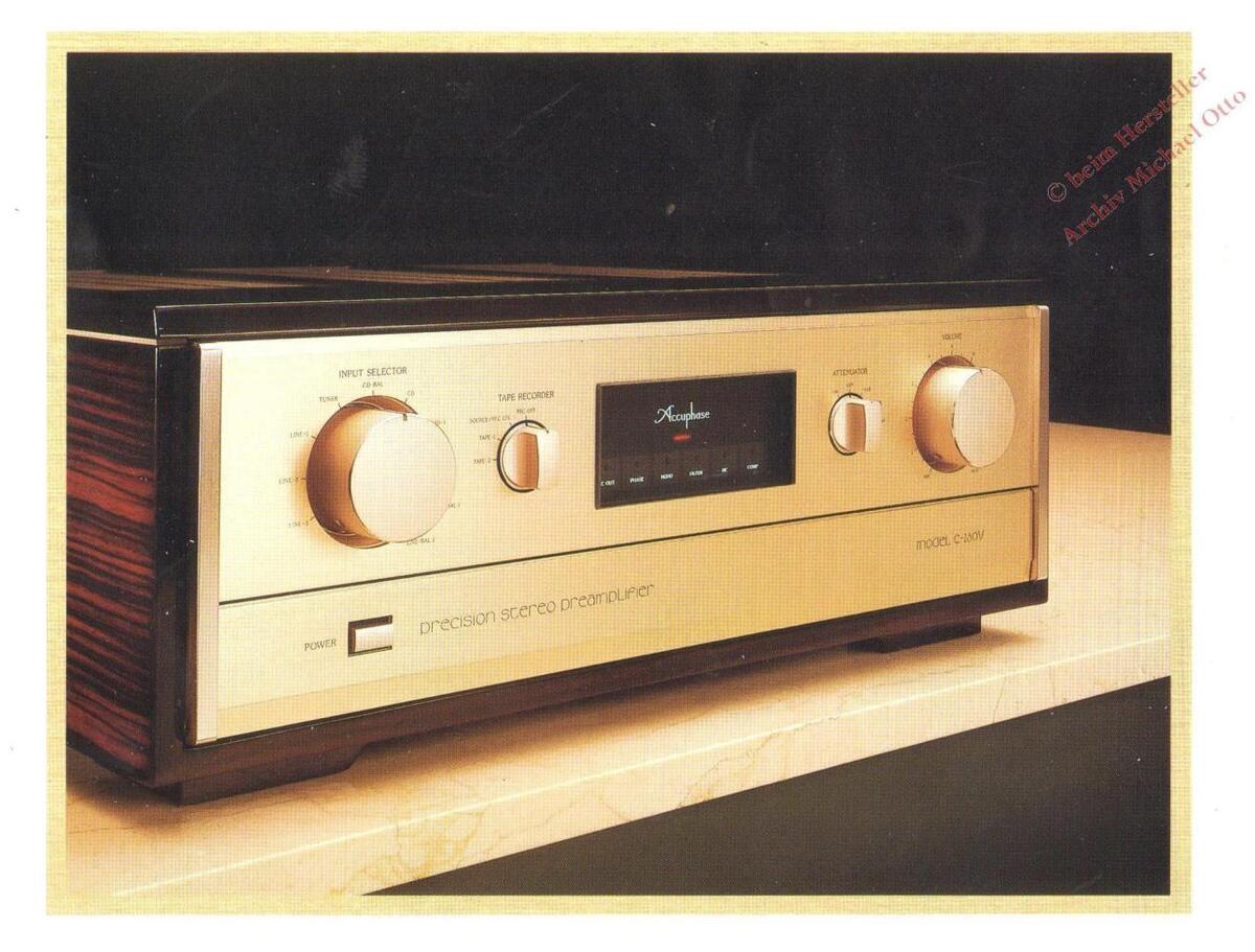
C-280V
High-Quality, Balanced Transmission Line Amplifier Class A Push-Pull Amplifier with DC Servo System for All Stages Independent Four Power Supplies for Left and Right Amplifier and Equalizer Circuits Conductive Plastic Audio Volume with Four Synchronized Variable Elements

Accuphase's reputable preamplifier C-280 was introduced to the market in December 1982, and about the same time the first CD players were produced. To exhibit the merits of CDs, the C-280 incorporated an innovative, cascode-type class A (all-stage) push-pull amplifier circuit and an analog equalizer. The C-280, which was regarded as the world's highest grade amplifier, incorporated the balanced power transmission system conforming to Accuphase's quality control.
In 1987, the C-280L, an improved version of the C-280 series amplifiers, incorporated a balanced circuit composed of two amplifiers. The C-280L made it possible to receive signals from CD players, power amplifiers, and other audio equipment to the C-280L via balanced cables. The highly sophisticated C-280L was then considered the king of preamplifiers.
Now, the C-280V, the most perfect preamplifier yet produced, has made its debut. It was developed based on Accuphase's established techniques with the concept that preamplifiers should correspond to various program sources and have a perfect signal transmission circuit
All the circuits of the C-280V have been newly developed. The most outstanding characteristic of the C-280V is that only one circuit is needed to transmit both balanced and unbalanced signals without passing through any additional circuits, which can cause deterioration of sound quality. The C-280V, which has an ideal amplifier circuit, incorporates an analog equalizer with an input circuit exclusively used for signals from MM or MC cartridges.
The power supply circuit of a preamplifier is as important as that for the power amplifier and has a great influence on audio quality. Because a high capacity is demanded from the power supply circuit, the C-280V's amplifiers and equalizers (both left and right) are equipped with independent power supplies.
To further improve the audio quality, the C-280V incorporates four power supplies, each with an independent transformer.
The volume control, which was exclusively developed for the C-280V, uses an innovative, newly developed conductive plastic resistor. Instead of the collectors rotating, the resistor elements rotate, thus reducing a great deal of the
High-Quality Balanced Transmission Line Amplifier with Class A Push-Pull Circuitry. Each Amplifier Unit with CP (Conductive Plastic) Audio Volume, Supported by Independent Four Power Supplies.
metal contact area. This has made it possible to eliminate sound deterioration to almost nil
Each amplifier unit is secured with a thick aluminum housing and mounted on an 8-mmthick rigid aluminum frame. This insulates each amplifier unit and effectively cuts mechanical vibration.
Accuphase's high quality C-280V incorporates gold plated printed circuit boards as well as finest quality copper wire.
High-Quality, Balanced Transmission Line Amplifier
The line amplifier can be compared with a city's main street since all sources must pass through the line amplifier. Accuphase has incorporated a balanced transmission circuit which has symmetrical signals paths, each for plus and minus signals, the phases of which are opposite each other and are transmitted simultaneously. This system eliminates noise effectively, which is why it has been adapted by broadcasting stations and audio professionals.
Recently, a high frequency noise has increased with the use of ever increasing numbers of home electronics equipment. Such noise intrudes through power lines or signal cables and reduces audio quality. The balanced transmission system cuts out such noise effectively
The line amplifier of the C-280V is a high quality balanced transmission line amplifier (refer to Fig. 2). The circuit (a) works as a balanced transmission line amplifier, while circuit (b) works as an unbalanced transmission line amplifier. The C-280V incorporates three differential amplifier units. AMP1 is for input use and AMP2 and AMP3 are for output use. In balanced transmission, signals can be input from both the plus and minus terminals of AMP1. The signals are then amplified and output to AMP2 and AMP3 feeds back its output to AMP3 while AMP3 feeds back its output to AMP3 while AMP3 feeds back its output to AMP2. Both AMP2 and AMP3 work together, producing symmetrical low impedance signals. In this circuit, even if either one of the output lines is grounded, normal output signals can be obtained. Therefore, in unbalanced transmission, each one of the input lines and the output lines can be grounded to obtain unbalanced output signals. Since only one circuit is used for bal-
anced and unbalanced transmission, there is no difference in audio characteristics between balanced and unbalanced transmission, and therefore an ideal amplification is achieved
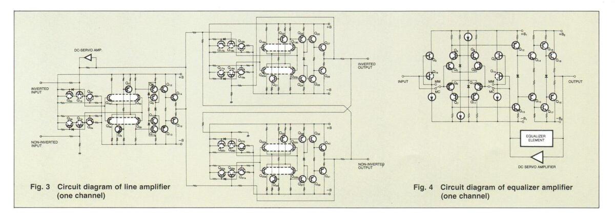
Class A (All-Stage) Push-Pull Amplifier with DC Servo System
Fig. 3 is the circuit diagram of the C-280V's line amplifier. All the amplifier units incorporate Accuphase's original symmetrical push-pull circuits. Since electrical stability is demanded for the input circuits, all the input circuits are the cascode source follower type, thus achieving stable operation in a wide frequency range from the low frequency to the ultra-high frequency. The output stage employs a complementary darlington push-pull circuit, keeping low input impedance and excellent linearity in a wide output range.
These amplifier units are DC amplifiers. In DC amplifiers, even minute direct current in the outout signals can cause noise. The C-280V incorporates an effective DC servo circuit which prevents any DC drift.
Independent Power Supplies for Left and Right Amplifiers and Equalizers
The C-280V incorporates four independent power supplies (the total capacitance of the filters is 120,000µF) for best analog reproduction.
All the amplifier units are equipped with broad-range constant-voltage power supplies, thus preventing interference between the amplifiers.
Accuphase's Exclusive Conductive Plastic Audio Volume
An amplifier needs a good audio volume control. The C-280V uses a new innovative conductive plastic (CP) type volume control similar to that used in sophisticated recording studios. A CP resistor is a variable resistor with little contact resistance, thus ensuring low audio distortion. It is processed at high temperature after a resistor element is printed on it and has gold-plated brush contacts.
Each external terminal is combined into a single unit made of only one metal type thus reducing distortion. Note that the brush of the CP


-
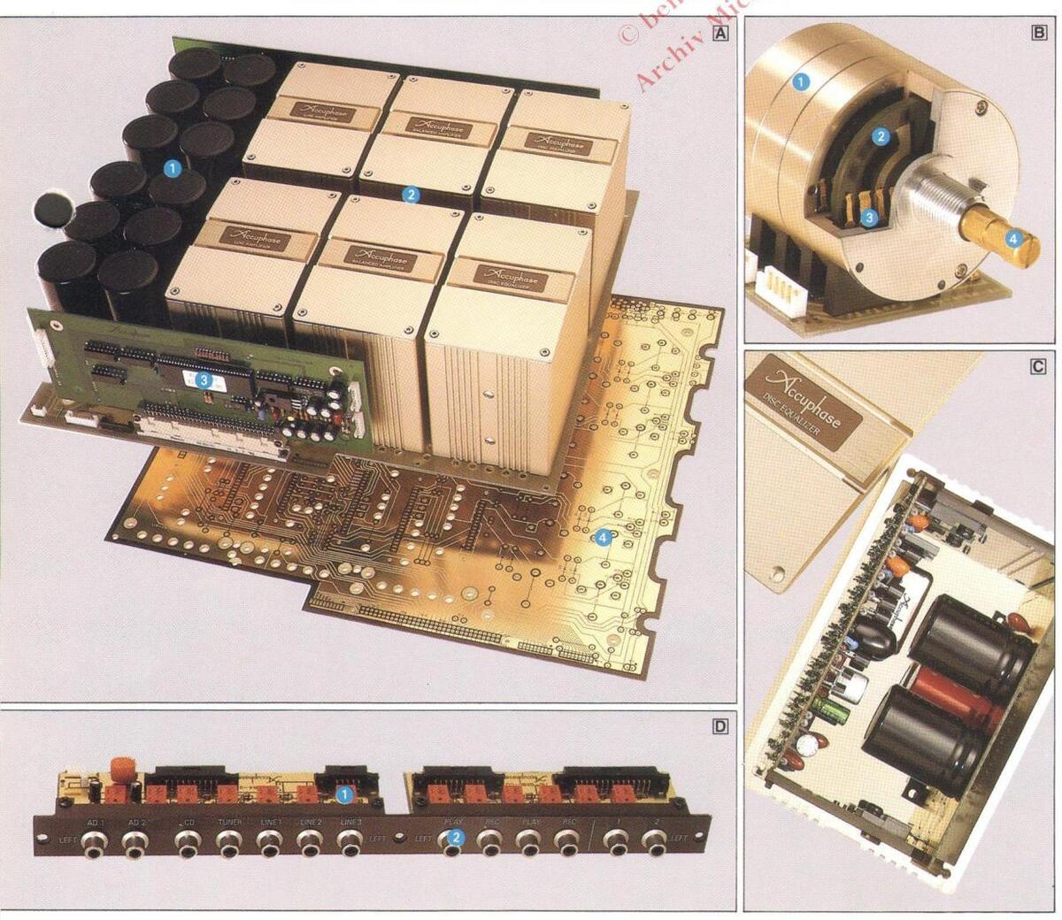
Each amplifier unit and filters (capacitors) on the mother PC board
Capacitors used for filter with a total capacitance of 120 000µF
- 2 A total of six left and right amplifier units
- Microcomputer controlled logical circuit
-
Microcomputer control of gradient assembly
Mother PC board with copper plate coated with gold
-
B CP (conductive plastic) audio volume with four synchronized variable elements
- High precision aluminum cut-out case CP resistor
- 3 Gold coated multi-contact brush 4 Thick bronze shaft (8-mm dia.)
- C An amplifier unit, which has an exclusive constant voltage power exclusive constant voltage power supply, mounted in a thick aluminum housing. (The picture is an equalizer amplifier unit.)
-
D Signal switching assembly, which directly connects to all the input and output terminals, controlled by the logical relay-controlled circuit. 1 Closed type relays filled with nitrogen
- gas
- gas Pigh-durability, custom-made rhodiup-

resistor does not rotate but the resistor element does. This uniquely constructed component with less contact points, is an ideal greaseless variable resistor.
Each 8-mm thick brass shaft of four ganged elements is supported by an aluminum bearing. The elements are installed in a thick closed aluminum casing that acts as a shield to improve audio quality. The resistance of the C-280V's CP resistor can be varied smoothly with a tracking error value of as little as 0.5dB max. (actual measured value) at -60dB.
High Quality and Stable Logical Relay-Controlled Signal Switching Circuit.
In principle, signal path lines should be as short as possible to avoid any deterioration of audio quality. But, to switch audio signals with a mechanical switch, sometimes necessitates long signal lines. Further, a mechanical switch itself, over a period of time deteriorates audio quality, since the switch can be worn out by sulphurized gas or cigarette smoke. This is the reason the C-280V uses the logical relay control system to switch signals. In this system, the signals are switched by relays which are electronically controlled with a logical circuit.
Since this system requires reliable relays, Accuphase uses a closed-type relay filled with nitrogen gas, which has been developed for audio and radio equipment use. The contact of this relay is a cross-bar twin type, made of goldpalladium and silver-palladium alloys, which are highly durable and low in contact resistance.
Phono Equalizer Amplifier Matching MM and MC Cartridges
In this CD age, ironically, some records are becoming more and more valuable. The C-280V incorporates a newly developed phono equalizer that can reproduce the excellent characteristics of analog recordings. Fig. 4 is the circuit diagram of the C-280V's phono equalizer, which is a symmetrical push-pull circuit.
The block diagram (Fig. 1), shows the C-280V's exclusive input circuits for excellent performance from MM and MC cartridges. High impedance MM cartridges can match FETs (Q1a, Q1b, Q2, Q3) that have a high S/N ratio.
On the other hand, MC cartridges are low in
impedance. Thus the differential input circuit is composed with low noise elements (Q5, Q6, Q9, Q10), which have made it possible to lower the impedance of the NFB loop and noise generated when playing back music.
Aluminum Housing with 8-mm-thick Hard Aluminum Frame for Perfect Shielding and Prevention of Vibration
The C-280V consists of a total of six amplifier units (left and right line input and output amplifiers), each of which has an exclusive power supply. To prevent interference between amplifiers, they are secured in a thick aluminum housing. Similarly, elements used for the output and power supply circuits have an aluminum housing to prevent vibration and heat radiation.
The housing is mounted on an 8-mm-thick hard aluminum frame, to which the main circuit board is also mounted. Thus the C-280V is perfectly free from electrical interference as well as mechanical vibration.
Twelve Input Terminals and Six Output Terminals
The C-280V incorporates many input and output terminals, thus accommodating various music sources. The C-280V has hine RCA phono jacks (for a CD player, a tuner, three lines inputs, two tape recorders, and two record players) and three balanced input terminals (for a CD and two line inputs). There are six output terminals (for two RCA phono jacks, two balanced outputs, and two tape recorders).
As input and output jacks must have durability without oxidizing, they should not be made of a soft material which can be easily damaged by taking plugs in and out frequently. The C-280V uses Accuphase's exclusive rhodium-plated jack. Rhodium-plated jacks are superior to gold-plated jacks electrically, and are being used on equipment for radio broadcasting and computers. A 1-µm-thick rhodium plating can withstand 100,000,000 operations (of putting in and taking out plugs), which outlasts any other similar plating.
Five-Step Rotary Attenuator
Turn the attenuator knob counterclockwise to
mute the sound, and turn the knob clockwise to select -6dB, -20dB, and -30dB levels. This attenuator is useful when searching for particular music or alternatively when needing to mute the sound to answer a telephone.
Independent Level Control
Left and right level controllers for attenuation are fully independent of each other. The controllers can adjust in 0.5-dB steps from 0 to -6dB and 1dB steps up to -14dB accurately. The surface of the low-distortion type resistor element used for the independent level control is perfectly smooth.
Phase Switching Mechanism Without Affecting Audio Quality
The C-280V incorporates a phase switch, with which the absolute phase of the audio signal can be adjusted. This does not affect audio quality since the positive and negative lines of the balanced amplifier are simply interchanged when this switch is on, thus reversing the phase. The C-280V does not incorporate a complicated phase reversing circuit, which may have a detrimental effect on audio quality.
Other Functions
Tape recording and playback in combination with a preamplifier can be done with ease. The C-280V can be connected to two tape recorders. Monitoring is possible during tape recording and playback operations.
The C-280V incorporates a compensator switch, which can be used to emphasize lowpitched sound when the audio volume is low. The compensator automatically changes the characteristics of the audio output in accordance with the position of the volume control. The C-280V incorporates a sub-sonic filter to cut out ultra low-pitched noise. This filter is indispensable when reproducing records and cuts out low-pitched noise (10Hz, -18dB/oct.) without deteriorating the audio quality.
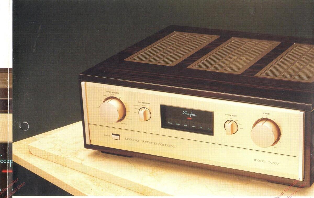
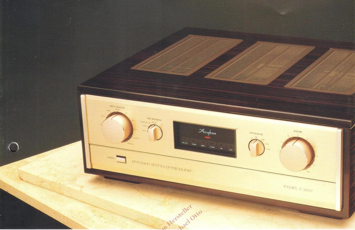
Luxurious Persimmon Wood Case
The front panel is made of thick aluminum with a gold satin finish and the casing is made of luxurious persimmon timber, which enhances any decor.
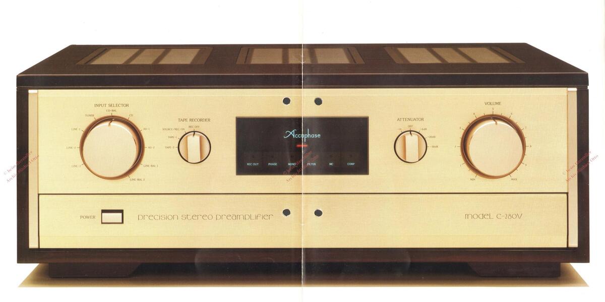
The C-280V is a precision stereo preamplifier. The symmetrically arranged switches and knobs on the front panel will match a stereophonic music atomosphere. The user will feel Accuphase's technique from the neatly arranged function switches on the subpanel. Incorporating amplifier units mounted in a thick aluminum housing and neatly arranged terminals, extremely high precision characteristics have been materialized inside and utside of the C-280V.
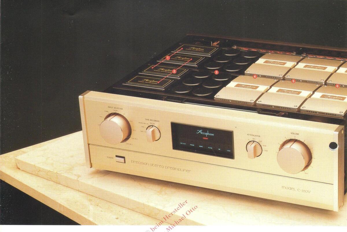
Internal Layout
- 1 Power transformers for left- and right-channel
- 2 Power transformers for left- and right-channel
- Left- and right-channel power supply filter capacitors 4 Left- and right-channel line amplifier units
- Left- and right-channel balanced amplifier units
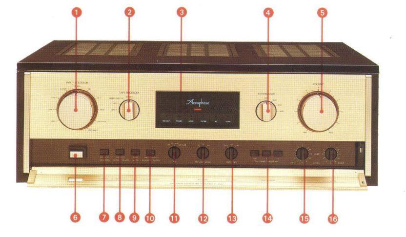
Front and Rear Panels
- 1 INPUT SELECTOR LINE-3, LINE-2, LINE-1, TUNER, CD-BAL, CD, AD-1, AD-2, LINE-BAL1, LINE-BAL2
- Recording output on/off, tape monitor switch REC OFF, SOURCE/REC ON, TAPE-1, TAPE-2
- Function LEDs POWER: ON/OFF; OUTPUT: ON/OFF; REC OUT: ON/OFF; PHASE: INV/NON-INV; STEREO/MONO;
- ATTENUATOR -∞, OFF, -6dB, -20dB, -30dB VOLUME control
- 0 BALANCED/UNBALANCED switch BALANCED/UNBALANCED
- OUTPUTS PHASE switch
- MODE switch STEREO/MONO
- 10 SUBSONIC FILTER switch 10Hz - 18dB/oct
- EQUALIZER GAIN switch
- 10 MC cartridge load inpedance switch 10Ω, 30Ω, 10ΩΩ TAPE COPY switch 1→2, OFF, 2→1 COMPENSATOR switch
- E Left channel level control
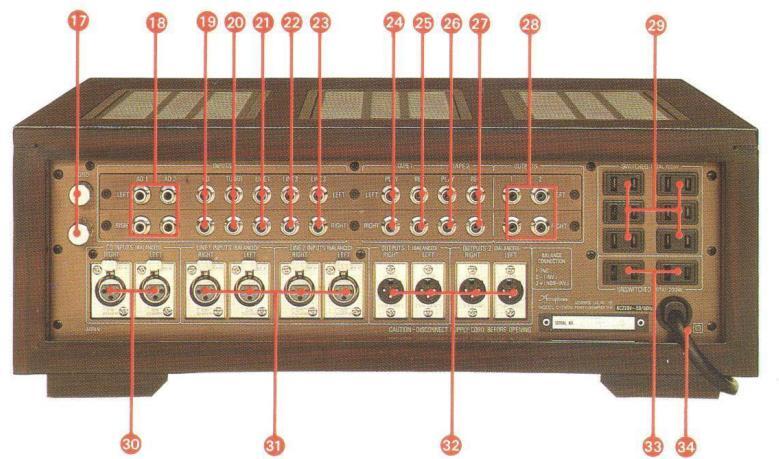
- AD (analog disc) input jack CD unbalanced input jack TUNER input jack
- 20 TAPE-1 tape input jack
- TAPE-1 tape input jack TAPE-1 recording output jack TAPE-2 tape input jack
- XLR-3-31 equivalent: 1) Ground, 2) Inverted (-),
- 3) Non-inverted (+) (Suitable connector: XLR-3-12C equivalent)
-
- XLR-3-32 equivalent: 1) Ground, 2) Inverted (-), (Suitable connector: XLR-3-11C equivalent)
- AC outlet (unswitched)*
*These switched and unswitched AC outlets may not be regulations applicable in the particular country to where
A Each amplifier unit and filters Each amplifier unit and filters (capacitors) on the mother PC board Capacitors used for filter with a total
- A total of six left and right amplifier units
-
arranged neatly
Microcomputer controlled logical circuit assembly
Mother PC board with copper plate
-
B CP (conductive plastic) audio volume with four synchronized variable elements
- High precision aluminum cut-out case CP resistor Gold coated multi-contact brush
- C An amplifier unit, which has an exclusive constant voltage power supply, mounted in a thick aluminum housing. (The picture is an equalizer amplifier unit.)
-
D Signal switching assembly, which directly connects to all the input and output terminals, controlled by the logical relay-controlled circuit. 1 Closed type relays filled with nitrogen
- gas 2 High-durability, custom-made rhodiup-

GUARANTY SPECIFICATIONS
(Guaranty specifications are measured according to EIA standard RS-490. AD denotes Analog Disc in
Performance Guaranty: All Accuphase product specifications a guaranteed as stated.
• Frequency response
| i i oquolioj i oopolioo | ||
|---|---|---|
| Balanced input (CD/LI | NE): | |
| 1.0 to 350,000Hz | +0 | -3.0dB |
| 20 to 20,000Hz | +0 | -0.2dB |
| Unbalanced input (CD, | TUNE | ER/LINE/TAPE PLAY |
| 1.0 to 350,000Hz | +0 | -3.0dB |
| 20 to 20,000Hz | +0 | -0.2dB |
20 to 20,000Hz +0.2 -0.2dE Total harmonic distortion
0.005% (at all input terminals
Input terminal Input sensitivity Rated output Input sensitivity output Input impedance. AD:MM 2.0mV 0.5mV 47kΩ AD:MC/26dB 0.1mV 0.025mV 100, 300, 1000. AD:MC/32dB 0.05mV 0.125mV 100, 300, 1000. Balanced 126mV 31.5mV 40k0(20k0)
Rated output/impedance
| Balanced output: | 2.0V | 10Ω (5Ω/5Ω) XLR type |
|---|---|---|
| conne | ctor | |
| Unbalanced output: | 2.0V | 5Ω RCA phono jack |
| Tape rec output: | 126m | / 200Ω RCA phono jacl |
S/N ratio
|
Input-shor
calib |
ted, IHF-A
rated |
||
|---|---|---|---|
|
Input
terminal |
Rated input
S/N |
Input-
converted noise |
EIA S/N |
| AD:MM | 90dB | -140dBV | 86dB |
| AD:MC/26dB | 78dB | -152dBV | 76dB |
| AD:MC/32dB | 72dB | -152dBV | 76dB |
| Balanced | 115dB | -128dBV | 95dB |
| Unbalanced | 115dB | -128dBV | 95dB |
| andard RS-490. AD denotes Analog Disc input.) |
|---|
|
Maximum output level (with a distortion of 0.005%,
20 to 20,000Hz) Balanced output: 7.0V XLR type connector Unbalanced output: 7.0V RCA phono jack Tape rec output: 19.0V RCA phono jack/with AD ionut: |
|
input
• AD maximum input voltage (with a distortion of 0.005% at 1kHz) MM input: 300mV MC/26d8 input: 15mV MC/26d8 input: 7.5mV • Minimum load impedance Balanced output: 600Ω Tape rec output: 00kΩ • Gain Balanced input → Balanced output: 18dB Unbalanced input → Balanced output: 18dB Unbalanced input → Balanced output: 18dB Unbalanced input → Balanced output: 18dB Unbalanced input → Balanced output: 18dB AD (MM) input → Balanced output: 18dB (NM) input → Balanced output: 18dB Dibalanced input → Tape rec output: 0dB AD (MM) input → Tape rec output: 54dB AD (MC: 26/32dB) input→Tape rec output: 62/68dB AD (MC: 26/32dB) input→Tape rec output: 62/68dB AD (MC: 26/32dB) input→Tape rec output: 62/68dB AD (MC: 26/32dB) input→Tape rec output: 62/68dB AD (MC: 26/32dB) input→Tape rec output: 62/68dB AD (MC: 26/32dB) input→Tape rec output: 62/68dB AD (MC: 26/32dB) input→Tape rec output: 62/68dB AD (MC: 26/32dB) input→Tape rec output: 62/68dB AD (MC: 26/32dB) input→Tape rec output: 62/68dB AD (MC: 26/32dB) input→Tape rec output: 62/68dB AD (MC: 26/32dB) input→Tape rec output: 62/68dB AD (MC: 26/32dB) input→Tape rec output: 62/68dB AD (MC: 26/32dB) input→Tape rec output: 62/68dB AD (MC: 26/32dB) input→Tape rec output: 62/68dB AD (MC: 26/32dB) input→Tape rec output: 62/68dB AD (MC: 26/32dB) input→Tape rec output: 62/68dB AD (MC: 26/32dB) input→Tape rec output: 62/68dB AD (MC: 26/32dB) input→Tape rec output: 62/68dB AD (MC: 26/32dB) input→Tape rec output: 62/68dB AD (MC: 26/32dB) input→Tape rec output: 62/68dB AD (MC: 26/32dB) input→Tape rec output: 62/68dB AD (MC: 26/32dB) input→Tape rec output: 62/68dB AD (MC: 26/32dB) (MC)(MC) (50/60Hz) • Code, -30dB, -∞ • Semiconductors used Power requirement 100V. 117V, 220V. 240V, 50/60Hz • Power consumption S6W • Dimensions 468mm (18-7/16') width. 171mm (6-3/4'') height max. 3980mm (15-5/6') depth • Weight 25.2Kg (55.6 lbs.) net 30.3kg (66.8 lbs.) in shipping carton |
|
THD vs.
Input Voltage |
e.1 | ||||
|---|---|---|---|---|---|
|
Hodelê (C-2889
Serialê) Date ( |
8.81 | ||||
|
Enpus ( RD)
Output : Tape Rec. |
X | ||||
|
Load Impedance:
EIR std. Dummy Gain (at lkHz); |
8.081 | N | |||
|
36.65 dB
Max Input Voltage 28Hz1 41.25mV 1kHz1 367.11mV |
0.8801 | N. | X | Ż. | |
|
28kHz:3425.35mV
:28Hz :1kHz |
e. 9569.9 | 1 |
Input voltage vs. THD (MM input to tape
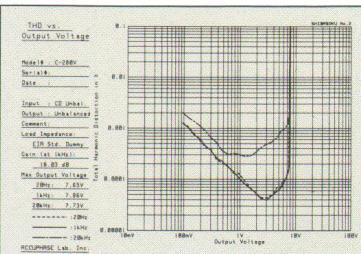
Output voltage vs. THD (Unbalanced
| requency s- |
HEALTT MOR |
ALL CHILL MILL | |||||
|---|---|---|---|---|---|---|---|
| Characteristics | 11 | ||||||
| V865-2 ; 61ebol | |||||||
| fariala: 8 | 1 | ||||||
| Input : CB Unbsi. | N | ||||||
| output > Unkalanced. | Pp. | ROOM TC | entre | ||||
| LIR Std. Dunny | |||||||
| 11 | 111 | ||||||
| -18 | 121 | 1111 | |||||
| -12 | |||||||
| -[4 | +++ | ||||||
| -16 | 111 | 111 | |||||
| -18 | 111 | 111 | - KIII BA |

enrich life through technology


Compensator characteristics


 Loading...