

Page 1
m Current feedback circuit topology assures great sound and stable
operation m Printed circuit boards using T eflon base m Fully modular
construction with separate units for all amplifier stages m Balanced
output stage with bridged feedback m Complete mono construction
with separate left/right transformers m Logic-controlled relays for
shortest signal paths m Optional analog record playback capability
Page 2
All preamplifiers from Accuphase are based on
balanced signal transmission, taking a nocompromise approach to quality . Furthermore, they
reflect the rich experience accumulated by
Accuphase during many years of building state-ofthe-art components. The C-275V is a fully
redesigned successor to the C-275, making
extensive use of sophisticated technology first
introduced in the highly renowned C-290V. As an
analog preamplifier, it has been honed to an even
higher degree of perfection. Every single part was
carefully selected through intensive listening tests.
It offers a full complement of sound tailoring features
such as tone controls and a loudness compensator.
The basic circuit design employs current feedback
topology developed by Accuphase, assuring
outstanding performance combined with excellent
sound quality.
As shown in Figure 1, in its standard configuration
the C-275V is a dedicated line amplifier, but by
installing an optional phono equalizer unit in a
special slot on the rear panel, it allows high-grade
analog disc reproduction as well.
In keeping with the aim of creating the ideal line
amplifier, the balanced output stage of the C-275V
employs symmetrically bridged feedback, resulting
in a floating design where the signal is kept entirely
separate from the ground line. This lavish approach
is highly desirable in a line amplifier and assures
the best possible performance. The printed circuit
boards are an important element of a preamplifier
in regards to electrical performance as well as sound
quality . In the C-275V , these are made from a Teflon
material (glass fluorocarbon resin) with low dielectric
constant and low loss, for optimum sound.
Less frequently used controls are located behind a
sub panel, and the elegant gold-colored panel face
has a stylish appeal. Even in the smallest detail,
the C-275V exudes an atmosphere of sheer class
which makes this analog preamplifier a joy to own
and rapture to listen to.
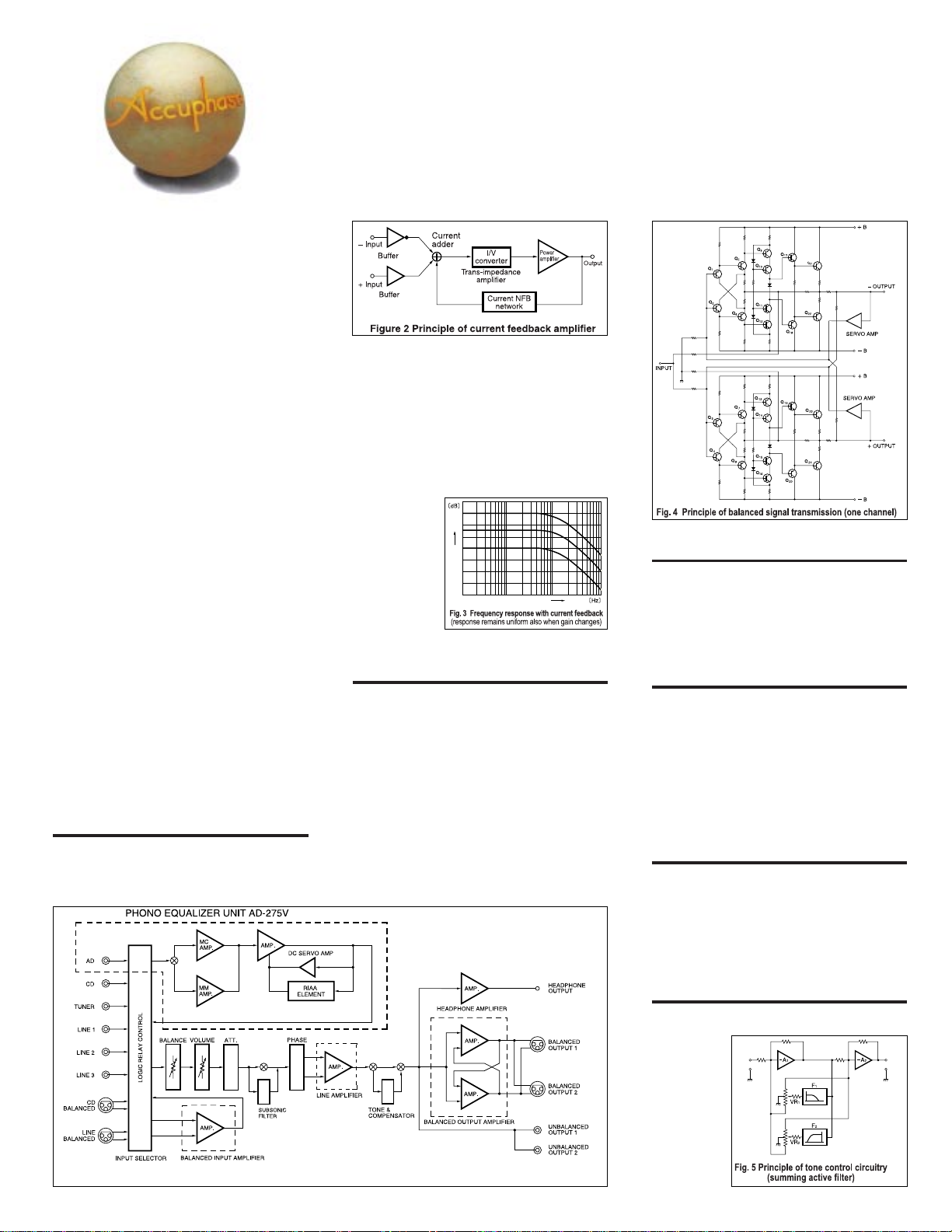
Current feedback topology prevents phase
shifts
The amplifying circuits in the C-275V use the current
feedback principle for negative feedback. Figure 2
shows the operating principle of this design. At the
input point of the feedback loop, the impedance is
(Option)
The new joy of analog – realized in a superb high-end preamplifier.
Current feedback technology , T eflon-based printed circuit boards, four
separate unit amplifiers, fully dual-mono construction with separate
power supplies. Optional phono equalizer unit allows top-quality analog
disc reproduction.
kept low for current detection. A trans-impedance
amplifier converts the current into a voltage to be
used as the feedback signal. Since the impedance
at the current feedback point (current adder in Figure
2) is very low, there is almost no phase shift. Phase
compensation therefore can be kept at a minimum.
A minimal amount of NFB results in maximum
improvement of circuit parameters. The result is
excellent transient response and superb sonic
transparency, coupled with utterly natural energy
balance.
Figure 3 shows
frequency
response for
different gain
settings of the
current feedback
amplifier. The
graphs demonstrate that response remains
uniform over a wide range.
Balanced output stage with bridged feedback
In balanced signal transmission, two identical
signals are transmitted simultaneously with inverted
phase and combined at the receiving end, thereby
canceling out common-mode noise and interference.
This principle is one of the requirements for truly
high-quality sound.
The principle of balanced sound transmission is
shown in Figure 4. The outputs of the two amplifiers
are connected to form a cross-feedback loop, which
sends the symmetrical (+) and (–) signals with low
impedance to the next stage. The signals are
isolated from the ground line, resulting in an ideal
balanced circuit. Even if one side of the output is
grounded, both amplifiers continue to operate, and
the output voltage does not change.
(High)
Gain
Frequency
(High)
Discrete line amplifier for optimum sound
The line amplifier is a pure complementary pushpull circuit. It is b uilt from discrete components and
employs the superior current feedback principle.
Phase compensation can be kept to a minimum,
resulting in realistic ambience.
Printed circuit boards made from T eflon with low
dielectric constant and low loss
The printed circuit boards for the signal-carrying
circuits are made of Teflon, a glass fluorocarbon
resin material. Teflon has a stable, low dielectric
constant as well as superior heat resistance,
excellent high-frequency characteristics, and many
other desirable properties. As a result, signal purity
is enhanced and there is a drastic improvement in
perceived S/N ratio.
* Teflon is a registered trademark of DuPont USA.
Complete mono construction with separate
transformers for left and right channels
The power supply of the C-275V employs a dualmono approach with separate power transformers
and filtering capacitors for the two stereo channels.
Each unit amplifier is equipped with a wide-range
low-impedance voltage regulator to eliminate
possible interference between stages.
Fig. 1 Block diagram of C-275V (one channel)
Tone controls use summing active filters for
highest sound quality
The tone control circuitry in the C-275V was
specially
designed with
summing
active filters
such as found
in high-quality
graphic
equalizers.
Figure 5
illustrates the
operation
principle of
Input
Output
Page 3

this circuit. The flat signal is passed straight through,
and only when an adjustment is required, the
characteristics are created at F1 and F2 and added
to the signal, thereby producing the desired change.
This design provides efficient control without
degrading signal purity.
Vibration-free design with unit amplifiers in
aluminum enclosures fastened to 8-mm
hardened aluminum chassis
The C-275V has four unit amplifiers, two each for
the line input and line output in each channel. Each
unit is powered by its own local voltage regulator
circuitry, and is housed in a strong aluminum
enclosure, to prevent interference between units.
Unit amplifier in thick aluminum housing
Logic-controlled relays for signal switching
assure high sound quality and long-term
reliability
The use of logic-controlled relays at strategic
locations makes it possible to keep signal paths
extremely short. The relays used in the C-275V are
high-performance hermetically sealed types as used
in professional communication applications. The
contacts are twin crossbar types plated with gold
and silver palladium alloy, for minimum contact
Hermetically sealed relays connected
directly to gold-plated input/output jacks
n Mother PCB with gold-plated
copper paths supports the four
unit amplifiers (line and
balanced amplifiers), as well
as filtering capacitors and
peripheral circuitry.
resistance and outstanding long-term reliability.
Other features
n Volume control designed for sonic purity
n Supplied remote commander for volume
adjustment and program source switc hing
n Dedicated headphone amplifier for superior
sound
n Versatile array of functions
m Tape recorder f acilities with monitor switch and
copy switch
m Output phase selector button
m Loudness compensator with three selectable
characteristics
m Subsonic filter removes ultra low frequency
noise
n Remote commander
RC-26
allows volume
control and input
source selection
* Photo shows the amplifier with
optional phono equalizer unit
AD-275V installed
Page 4

Dedicated Phono Equalizer Unit AD-275V
In its default configuration, the C-275V is a line preamplifier for reproduction of CDs and
similar sources. A udiophiles with a collection of analog records will welcome the capability
to install the dedicated phono equalizer unit AD-275V in a rear-panel slot, which allows
reproduction of analog discs with sonic quality of the highest caliber.
The unit uses printed circuit boards made from T eflon material (glass fluorocarbon resin)
and is housed in a sturdy aluminum case for complete protection against any external
interference. Highly reliable DIN standard connectors make the shortest possible
connection between input and amplification circuits. This assures outstanding S/N ratio.
The circuit diagram of the unit is shown below. Dedicated input stages are pro vided f or
MM and MC cartridges. T o get the best out of each pickup type , the MC input impedance
can be switched in three stages (10/30/100 ohms). MM input impedance is fixed to 47
kilohms. To match the output of the cartridge, MC gain can be set to 60 or 66 dB.
* The AD-275V can only be used in the Accuphase models C-275 or C-275V .
* The phono equalizer unit AD-275 designed for the Accuphase model C-275
can also be used in the C-275V.
Input
Equalizer
elements
n Circuit diagram of phono equalizer unit AD-275V (one channel)
n Phono equalizer amplifier assembly (one channel)
Output
DC servo amplifier
Guaranteed Specifications
* Guaranteed specifications are measured according to EIA standard RS-490. AD stands for "Analog Disc".
* Specifications are sho wn for phono equaliz er unit AD-275V installed.
m Frequency Response BALANCED/UNBALANCED: 3 - 300,000 Hz +0, –3.0 dB
m Total Harmonic Distortion 0.005% (for all inputs)
m Input Sensitivity, Impedance Sensitivity
m Output Voltage, BALANCED OUTPUT: 2 V, 50 ohms, XLR type connectors
Output Impedance UNBALANCED OUTPUT : 2 V, 50 ohms, RCA type phono connectors
m Signal-to-Noise Ratio Input shorted, IHF-A weighting
m Maximum Output Level BALANCED OUTPUT : 6.0 V, XLR type connectors
(0.005% THD, 20 - 20,000 Hz)
m Maximum AD Input Level MM INPUT : 125 mV
(0.005% THD) MC [60/66 dB] INPUT : 8 mV/4 mV
m Minimum Load Impedance
m Gain
m Loudness Compensation 1: +3 dB (100 Hz) 2: +6 dB (100 Hz) 3: +6 dB (100 Hz), +6 dB (20 kHz)
m Tone Controls Turnover frequency and adjustment range BASS : 300 Hz ±10 dB (50 Hz)
m Subsonic Filter 25 Hz -12 dB/octave
m Attenuator Characteristics –6 dB, –20 dB, –30 dB
m Headphone Jack Suitable impedance: 4 - 100 ohms
m Power Requirements 120V/230 V (Voltage as indicated on rear panel) AC, 50/60 Hz
m P ower Consumption 25 watts
m Maximum Dimensions Width 475 mm (18-11/16"), Height 150 mm (5-7/8"), Depth 404 mm (15-7/7")
m W eight 21.7 kg (47.8 lbs) net, 27.2 kg (60.0 lbs) in shipping carton
m Supplied Remote Remote control principle : infrared pulse
Commander RC-26 Power supply : 3 V DC (IEC R6 batteries x 2)
AD INPUT: 20 - 20,000 Hz –0.2 dB
Input
AD : MM 4.0 mV 1.0 mV 47 kilohms
AD : MC/60 dB 0.25 mV 0.063 mV 10/20/100 ohms
AD : MC/66 dB 0.125 mV 0.0315 mV 10/20/100 ohms
BALANCED 252 mV 63 mV 40 kilohms
UNBALANCED 252 mV 63mV 20 kilohms
TAPE REC: 252 mV, 200 ohms (with AD input)
AD : MM 90 dB 91 dB
AD : MC/60 dB 79 dB 84 dB
AD : MC/66 dB 75 dB 84 dB
BALANCED 114 dB 96 dB
UNBALANCED 116 dB 96 dB
UNBALANCED OUTPUT : 6.0 V, RCA type phono connectors
TAPE REC : 6.0 V (with AD input)
BALANCED/UNBALANCED OUTPUT
TAPE REC : 10 kilohms
BALANCED/UNBALANCED INPUT➝BALANCED/UNBALANCED OUTPUT
BALANCED/UNBALANCED INPUT➝REC OUTPUT: 0 dB
AD [MM] INPUT
AD [MM] INPUT
AD [MM] INPUT
AD [MC: 60/66 dB] INPUT
AD [MC: 60/66 dB] INPUT
Maximum Dimensions :
Weight : 190 g (419 lbs) (including batteries)
For rated output For 0.5 V output
Input
20 - 20,000 Hz +0, –0.2 dB
Input Impedance
S/N ratio at rated output
: 600 ohms
➝
BALANCED OUTPUT : 54 dB
➝
UNBALANCED OUTPUT : 54 dB
➝
REC OUTPUT : 36 dB
➝
BALANCED/UNBALANCED OUTPUT
➝
REC OUTPUT : 60/66 dB
TREBLE : 3 kHz ±10 dB (20 kHz)
Width 66 mm (2-5/8"), Height 175 mm (6-7/8"), Depth 20 mm (13/16")
EIA S/N
: 18 dB
: 78/84 dB
n FRONT PANEL
Input selector
LINE-BAL LINE 3 LINE 2 LINE 1
CD-BAL CD TUNER AD (OP)
Loudness compensator selector
Function LED indicators
Balance control
Volume control
Power s witch
Recording output/tape monitor selector
REC OFF SOURCE TAPE 1 T APE 2
Remarks
H
This product is available in versions for 120/230 V AC. Make sure that the voltage shown on the rear panel matches the AC line voltage in your area.
H
The shape of the AC inlet, plug of the supplied power cord, and AC outlet depends on the voltage rating and destination country.
H
These unswitched AC outlets may not be supplied depending on the safety standards or regulations applicable in the particular country to where the unit is destined.
n Supplied accessories m AC power cord
m Audio cables with RCA plugs
m Remote commander RC-26
Output ON/OFF button
Output phase selector button
Subsonic filter
Tone control switch /
BASS/TREBLE controls
Tape copy buttons
OFF 1 ➝ 2 2 ➝ 1
Stereo/mono selector button
Attenuator selector
OFF –6 dB –20 dB –30 dB
n REAR PANEL (Photo shows the amplifier with optional phono equalizer unit AD-275V installed)
Loudness compensator ON/OFF switch
Headphone jack
AD (Analog Disc) input
AD ground terminal
Equalizer gain selector
MM MC/60 dB MC/66 dB
MC cartridge load impedance selector
10 Ω 30 Ω 100 Ω
Line inputs
CD TUNER LINE 1,2,3
Tape recorder REC/PLAY jacks
Unbalanced outputs
Switched AC outlets
CD/LINE balanced inputs
a GND b Inverted [–]
c Non-inverted [+]
Balanced outputs (2 sets)
a GND b Inverted [–]
c Non-inverted [+]
AC power connector
(for supplied power cord)
H
H
H
H
* Specifications and design subject to change without notice for improvements.
http://www.accuphase.com/
PRINTED IN JAPAN E0010 851-0167-00 (AD1)
 Loading...