


High Quality, Ideally Balanced Transmission Line Amplifier Class A Push-Pull Amplifier with DC Servo System for All Stages Completely Separate Twin Mono Construction through Independent Power Supply A Newly Developed 4-Gang Audio Volume Control

A preamplifier or a "Control Center", as we call it here, is positioned between the power amplifier and such musical sources as a CD player, analog turntable, tuner, DAT recorder, etc., conveniently controlling the signal traffic and adjusting the signal volume to any desired level. This is the main function required of a preamplifier. However, it must also provide absolutely uncolored sound reproduction whereby the listener will not even notice its evictence
Employed by the very first model of the C-200 series preamplifiers is a pure complementary pushpull amplifier circuit, a truly ideal amplification circuit topology. As the series advanced, such additional circuit features as a direct coupled and cascode bootstrap circuit were added. Further, a balanced signal transmission circuit was very quickly employed for both the input and output stages, in order to further improve the audio quality.
In the C-260, the circuit perfection has been furthered by successfully developing an output circuit consisting of a single amplifier and no transformer. This is an ideally balanced signal transmission circuit, which does not require a common ground.
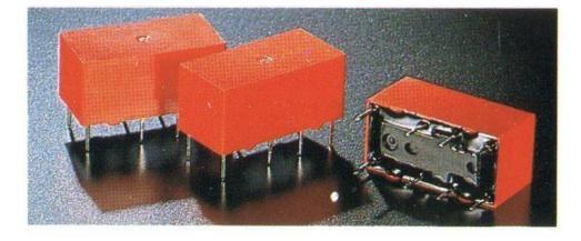
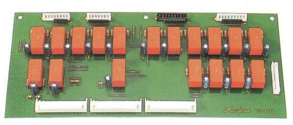
Accuphase's original logic relay control circuit has been employed to control complex audio signal traffic. The relays used are in a sealed casing, thus not exposing the electric contacts to air, which guarantees many years of perfect operation and high quality sound reproduction.
Special attention has been paid to the audio volume control, which normally tends to be a big
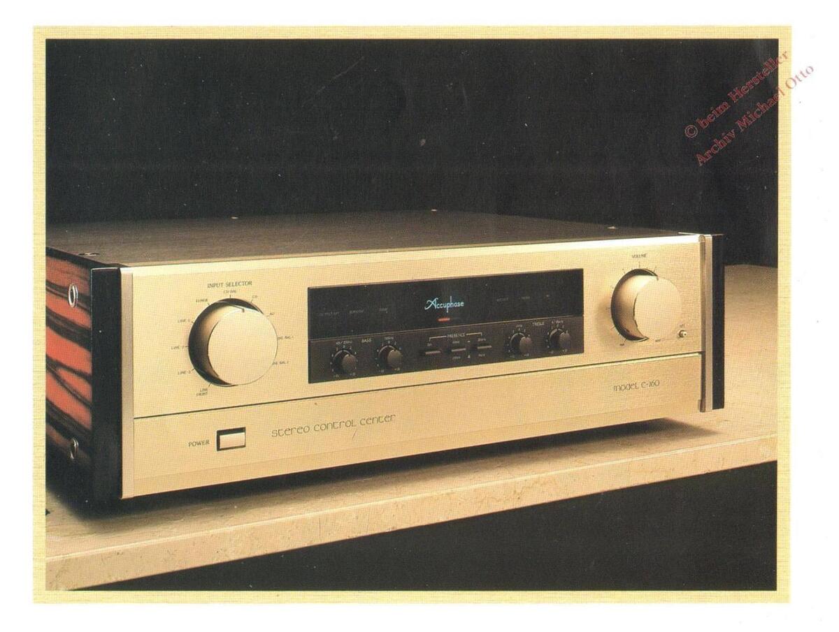
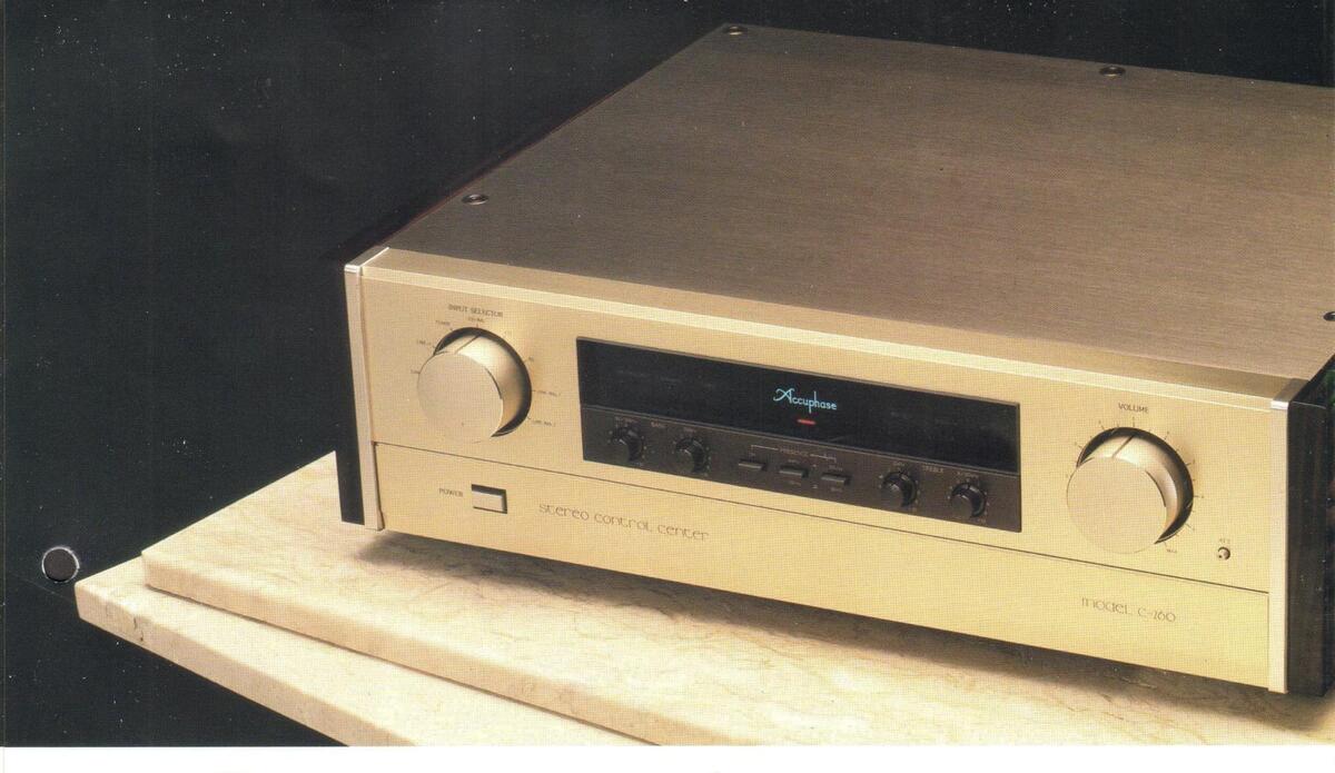
The unparalleled performance of the new Accuphase C-260 Stereo Control Center sets a new standard for the times. Dependability is built in with features such as Class-A push-pull circuits with exclusive power supplies that control line amplifiers for a balanced transmission system. And the complete twin mono construction incorporates independent power transformers. The versatility of the innovative C-260 makes it a unique and powerful stereo control center.
source of sound deterioration. The resistor element of the control is polished very precisely to reach a mirror-like smoothness. This newly employed volume control rotates the resistor elements unlike the conventional volume control, in which the collectors rotate. Thus, it successfully reduces the number of metal joints, which have been a source of sound deterioration, resulting in a remarkable improvement of the distortion characteristics.
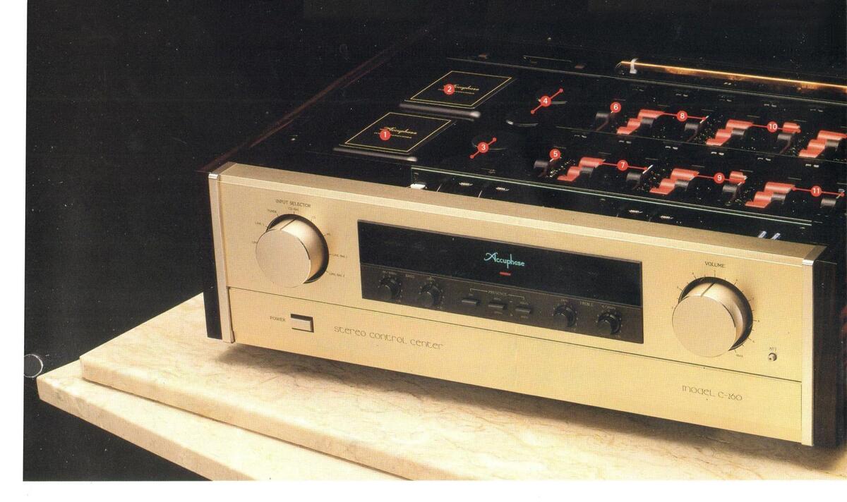
The C-260 provides a number of functions worthy to its designation as a "Control Center". All functions, other than those most commonly used, are logically organized under the hinged front subpanel. This assures the utmost ease of operation while maintaining a simple overall appearance.
We are confident that the C-260 incorporates all the technical know-how that Accuphase has accumulated since its foundation. It combines superb performance characteristics, excellent operational functions and beautiful design, all of which have been refined to their utmost, bringing you a step higher in the fascination of sound reproduction.
High Quality, Ideally Balanced Transmission Line Amplifier
Fig. 1 is a circuit block diagram of the C-260. The simplified functional explanation of the balanced line amplifier stage is shown in Fig. 2. As shown, AMP2 and AMP3 complement each other's operation. As a result, no common ground (G) exists in the circuit, thus forming an ideal amplifier circuit, when
operated in the balanced signal transmission connection as shown in Fig. (a). Even when unbalanced external equipment is connected to the inputs, outputs or both, the new balanced line amplifier circuit of the C-260 simply grounds the negative signals, while maintaining its original circuit configuration functioning fully as an ideal balanced transmission system. In other words, the circuit, through which signals pass, remains the same whether or not it is used with balanced or unbanced anced connections, thus successfully elimina any changes in the signal path that may deteriorate
This ideally balanced circuit based on the signal transmission theory, guarantees remarkably improved S/N characteristics, thanks to the excellent noise reduction when employed in a balanced connection.
Excellent Basic Characteristics for Line Input Amplifier
Fig. 3 shows a circuit diagram for the balanced input amplifier. It is based on Accuphase's original differential complementary push-pull input amplifier and cascode push-pull amplifier circuits. The input stage, in which a high-gm type FET is employed, consists of a constant current load type cascode circuit. The C-260 operates as a balanced input amplifier, when the input signals are connected to the positive (+) and negative (-) terminals. It operates as an unbalanced amplifier, when the input signals are connected to the common the input signals are connected to the common
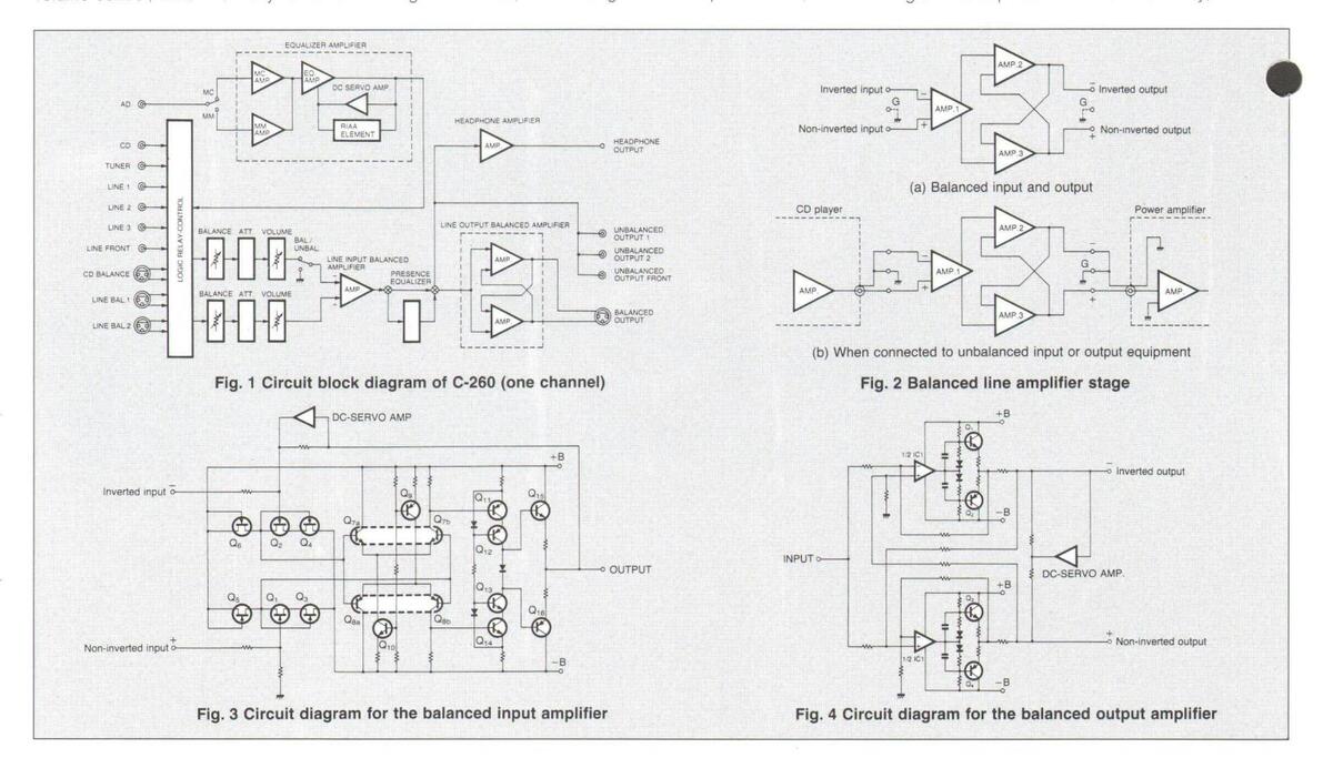
plifier stages are constructed in a direct coupled configuration with a DC servo circuit. Shown in Fig. 4 is the balanced output circuit diagram. It consists both of a differential operational amplifier circuit and a push-pull drive output circuit, thus achieving excellent low distortion and low impedance characteristics.
A Newly Developed 4-Gang Audio Volume Control
One of the most important functions of the "Control Center" is to control the audio volume without any sound deterioration. The volume control employed in the C-260 has resistor components, whose surace has been polished to a mirror-like smoothness, hus resulting in a remarkable low distortion characteristic and greatly reduced wear and tear. Moreover, the volume control has no sound deteriorating additives, such as grease applied between the collectors and resistors. Conventional volume controls have rotating collectors and fixed resistors connected to external terminals with leads going through rivet holes. The volume control employed in the C-260 instead has rotating resistors and fixed
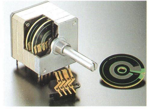
collectors that are connected directly to the external terminals. This construction has successfully reduced the number of metal joints from 5 to 3, thus greatly contributing to the improvement in sound quality. This volume control is a precision 4-ganged type, controlling the positive and negative signals of the left and right channels simultaneously. It is ganged so precisely to ensure a smooth rise in sound levels of both channels.
Completely Separate Twin Mono Construction for Amplifier and Power Supply Stages
Each of the equalizer amplifier, line amplifier and presence control amplifier has its own independent power supply. In addition, each channel is equipped with an exclusive power transformer in order to perfect a complete electrical separation between the two channels. Moreover, each of the two channels has its own unit amplifier, which is completely separated in construction in order to eliminate inter-channel interference.
Newly Developed High Quality Exclusive Headphone Amplifier
The primary purpose of a preamplifier is to control the signals entering the power amplifier, but headphones may also be connected for monitoring applications or during the late evening hours, when one can not listen to music at high levels. The C-260's DC servo, direct coupling headphone amplifier can ideally drive headphones with a wide range of impedances.
Presence Control Offers a Versatile 4-Point, 6-Frequency Control
The C-260 is equipped with a control that permits subtle adjustments of reproduced sound from a wide variety of musical program sources. Graphic equalizers are originally intended for this purpose, but their numerous controls often make them difficult to use.
The newly developed "Presence Control" of the C-260 is specially designed to achieve the most pleasing aural impression during music reproduction. Adjustments are made at preset turnover points with four controls governing six frequency ranges.
For instance, the center points of the mid-fre-
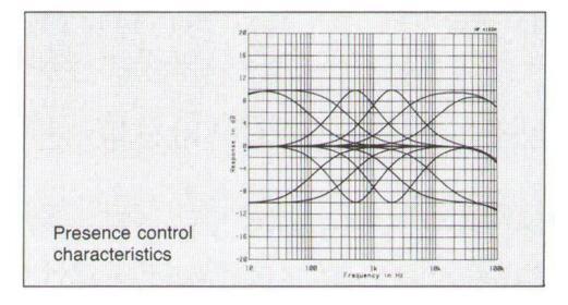
quency range are set at 500Hz and 2kHz. The 500Hz control can effect, for example, the timbre of rhythm instruments and the 2kHz control can be used to emphasize vocals or reduce traces of stringency.
Extensive listening tests were carried out to determine the Q factor for these controls, which expresses the steepness of the tone control curve. A value of Q=0.707 was finally chosen, as it provides the most natural sounding results with a wide variety of program sources.
The overall tonal energy balance can be adjusted with the Bass and Treble controls, which possess two switchable turnover frequencies.
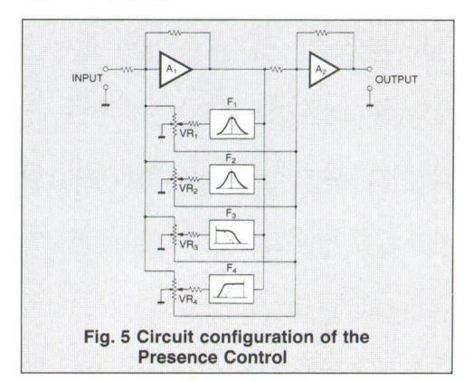
The circuit configuration of the Presence Control is shown in Fig. 5. It consists of a combination of summing filters, which feature the minimum of sound deterioration. All parts were strictly selected on the basis of their sonic performance, so that sound quality is not degraded when the control is in use. It can be, however, defeated from the circuit, when so desired.
Phono Equalizer Amplifier Matches All Types of MM and MC Cartridges
In this CD age, ironically, some records are becoming more and more valuable. The phono equalizer amplifier has been newly developed with the aim to perfectly reproduce the excellent characteristics of analog recordings. Fig. 6 is the circuit diagram of the C-260's phono equalizer.
As shown in the block diagram of Fig. 1, the C-

INTERIOR LAYOUT
l eft channel power transformer
each for MM and MC
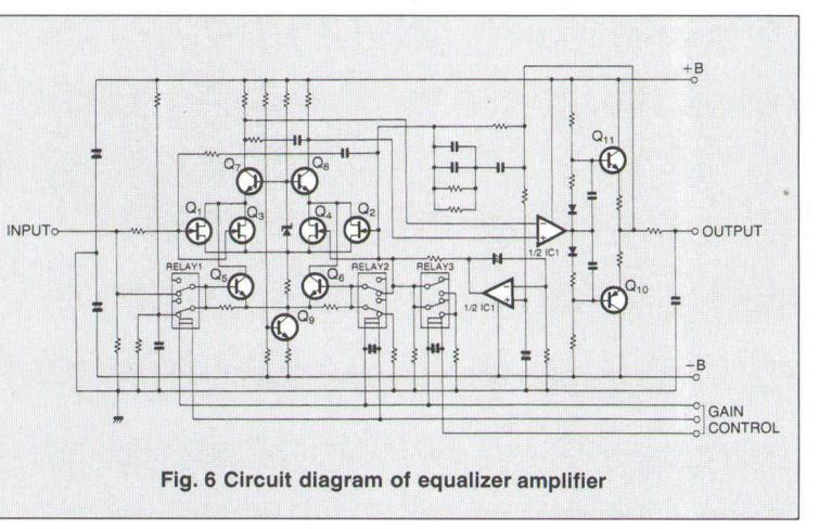
The gain of the phono equalizer can be switched depending upon the output of the phono cartridge
Highly Reliable Logic-Relays Permit Straight and Short Signal Paths.
One of the primary functions of the preamplifier is to selecting various functional modes. The audio sigjoints in relay switches can be worn out by sulplovs, for all the points that switch audio signals, a and industrial communication equipment use. Its
highly reliable performance guarantees a long time
Balanced to Unbalanced Transmission Conversion Amplifier Exclusively for Tape Output.
For the tape recording output, the C-260 provides output signals. Therefore, the balanced inputs can input sources. The C-260 provides two tape recor-
Unsurpassed Input/Output Versatility For Multiple Program Sources
was designed to accommodate a wide variety of
Of these, one pair each of inputs and outputs is
Each amplifier unit and filter capacitors mounted on the mother PC board and peripheral circuit boards
- Logic-relay drive power circuit Logic-relay drive p Logic relay circuit
- Resence control circuit
Other Features
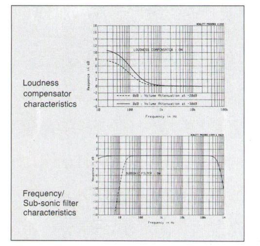
The C-260 incorporates a loudness compensator frequency energy at low audio volume. Its characwith the volume control position at -30dB or +4dB
An attenuator provided can instantaneously search for a certain position of a musical selection
Luxurious Persimmon Wood Sidepanels
The upper plate of the C-260 is made of thick unit is flanked by sidepanels made of exquisite natural persimmon wood to harmoniously blend in
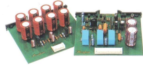
The phono equalizer amplifier has a dedicated power supply unit and features an exclusive input circuit compatible with all cartridges, including MM and MC.
The logic relay control circuit board incorporates highly reliable sealed relays charged with nitrogen.
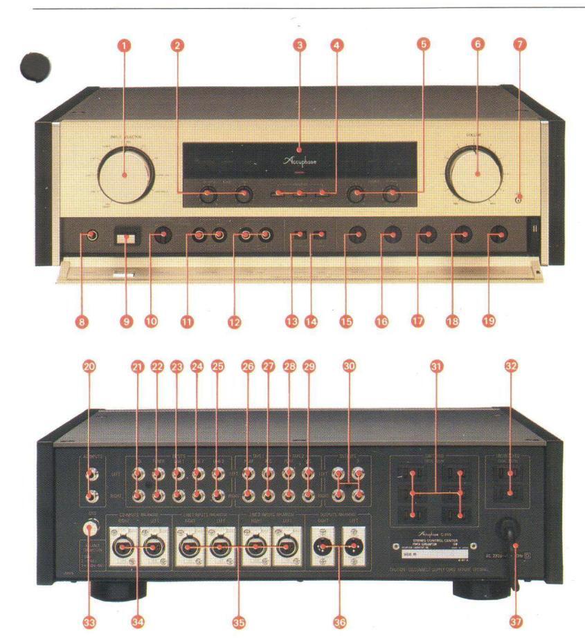
FRONT/REAR PANELS
- Input selector LINE FRONT, LINE-3, LINE-2, LINE-1,
- 2 Presence control (BASS)
- 40/100Hz, SUUHz Function display LEDs MUTING: ON/OFF, OUTPUT: ON/OFF, SUBSONIC: ON/OFF, COMP:ON/OFF, REC OUT: ON/OFF,
- 4 Presence control ON/OFF switch/
- ON/OFF, 40Hz/100Hz, 20kHz/8kHz Presence controller (TREBLE)
- 6 Volume control
- Attenuator (-20dB)
- 8 Headphone jack Power switch
- Output selector OFF. ALL. 1. 2. FRONT
- 1 Front output jack
- Pront LINE input jack Pront LINE input jack B Subsonic filter switch (17Hz: -12dB/Oct.)
-
Obsolution into similar (1712)
Councess compensator switch
Tape copy switch
1→2 OFE 2→1
- Becording output ON/OFF switch/
- 10 Mode selector switch REV., STEREO, MONO, R→L&R,
- L→L&R Balance adjustor
- Equalizer gain switch MC, MM1 (30dB), MM2 (36dB)
- 20 Analog player input jack 20 Unbalanced CD input jack 20 Tuner input jack
- Output jacks (unbalanced: 2) AC outlet (switched)*
-
- Remarks
*These switched and unswitched AC applicable in the particular country to
GUARANTEED SPECIFICATIONS
Performance Guaranty
- Accuphase product specifications are guaranteed as stated. Frequency characteristics BALANCED INPUT: [CD/LINE] 1.0 to 600,000Hz +0, -3.0dB
- 1000000012 +0, -0.2dB 201020,000Hz +0, -0.2dB JNBALANCED INPUT: [CD/TUNER/LINE/TAPE PLAY] 1.010600,000Hz +0, -3.0dB 201020,000Hz +0, -0.2dB INPUTC
-
- Total harmonic distortion
Otal narmonic distortion Q:005% (for all input terminals) Input sensitivity and input terminals
| Input se | Input | |||
|---|---|---|---|---|
| Input terminal | Rated output | 0.5-V output | impedance | |
| AD: MM1 | 8.0mV | 2.0mV | .47kΩ | |
| AD: MM2 | 4.0mV | 1.0mV | 47kΩ | |
| AD: MC | 0.25mV | 0.063mV | 100Ω | |
| BALANCED | 252mV | 63mV | 40kΩ | |
| UNBALANCED | 252mV | 63mV | 20kΩ | |
• Rated output and output impedance
Rated output and output impedance BALANCED OUTPUT: 2.0V, 500, XLR type connector UNBALANCED OUTPUT: 2.0V, 10, RCA jack TAPE REC: 252mV, 2000, RCA jack for AD input
Headphone jack
Headphone jack Suitable impedance 4 to 600Ω S/N and input converted noise
| (IHF-A cor | |||
|---|---|---|---|
| Input terminal |
S/N with
rated input |
Input
converted noise |
EIA S/N |
| AD: MM1 | 96dB | -138dBV | 90dB |
| AD: MM2 | 90dB | -138dBV | 90dB |
| AD: MC | 80dB | -152dBV | 70dB |
| BALANCED | 116dB | -128dBV | 96dB |
| UNBALANCED | 116dB | -128dBV | 96dB |
Maximum output level (distortion ratio 0.005%, 20 to 20,000Hz) BALANCED OUTPUT: 7.0V, XLR type connector UNBALANCED OUTPUT: 7.0V, RCA jack TAPE REC: 7.0V, RCA jack for AC input • AD maximum input voltage (distortion ratio 0.005%, 1kHz)
- Minimum load impedance
- BALANCED OUTPUT: 600Ω UNBALANCED OUTPUT: 1kΩ TAPE REC: 10kΩ
| Г | → REC OUTPUT: |
|---|---|
| Т | → BALANCED OUTPUT: |
| Т | → UNBALANCED OUTPUT: |
| Т | → REC OUTPUT: |
| → BALANCED OUTPUT: | |
| → UNBALANCED OUTPUT: | |
| - BEC OLITPLIT |
Presence controller
4-band system Frequency: 40Hz/100Hz switchable, 500Hz, 2kHz, 8kHz/20kHz switchable Variable range: ±10dB
Mars & And Mars & Fred
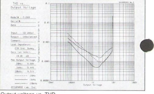
| THD vs. | 8.81 | TITUT I | prinna 1.6 |
94
1 |
LEASONU No.2 |
|---|---|---|---|---|---|
| Input Voltage | |||||
| fodel$ : C-268 | 1 | ||||
| ierial#: | 2 0.001 | ||||
| Date : | E 0.001 | 3 | i |||||||||||||||||||||||||||||||||||| | ||
| loput : AD | tion | ||||
| Output : Tape Rec. | tor | ||||
| Comment: HM 38d8 | 0 a abai | 1 | |||
| oad Impedance: | u | ||||
| EIA Std. Dummy | LO . | ||||
| Gain (at 1kHz): | XIII | +++++++ | |||
| 29.86 dB | |||||
| Max Imput Voltage | 0 a pppg1 | ||||
| 28Hz : .84V | |||||
| IkHz: .31V | |||||
| 20kHz: 2.74V | |||||
| :28Hz | |||||
| 8. 888881 | |||||
| :28kHz | laV | V#SI | Va991 | 11 | 187 |
| ACCUPHRSE Lab. Inc. | inport verträge |
-2005 Semiconductors 59 Tr., 25 FETs, 26 IC, 57 Di. Power supply and power consumption 100V, 117V, 220V, 240V, 50/60Hz 19W Dimensions 475mm (18-11/16") width, 149mm (5-7/8") height max. 375mm (14-3/4") depth • Weight 18.4kg (40.6 lbs.) net 23.4kg (51.6 lbs.) in shipping carton
oudnes. -30dB) ^4B (100Hz Sub-sonic filter
Attenuator
A Der franziski
to the second second
enrich life through technology
• Loudness compensator (when the audio volume set to
| 1 | Unbalanceu | CD | input | 10 | unbala | iceu | output | J |
|---|---|---|---|---|---|---|---|---|
| THD VS. | 8.13 | TTTHE I | 1 | TIT | LITTLE | | | TITTE | |
|---|---|---|---|---|---|---|---|
| Input Voltage | - II. | ||||||
| Hodel# : C-268 | |||||||
| Serial#: | N 8.81 | ||||||
| Date : | ÷ • | ||||||
| 6 | |||||||
| Input : AD | 2 | ||||||
| Output : Tape Rec. | 011 | ||||||
| Comment: MC | 0 8.881 | 1 | |||||
| Load Impedance: | 1 | ||||||
| EIR Std. Dumry | LOW | 1 | 1 | ||||
| Gain (at 1kHz): | 1 | / | |||||
| 59.88 dB | 1 | ||||||
| Max Input Voltage | |||||||
| 28Hz: 1.87mV | - 0.0001 | 1 | |||||
| 1kHz: 9.58mV | |||||||
| 28kHz: 98.52mV | |||||||
| - Unite | |||||||
| 100110 | 18865.8 | BuV | 1 mV | 18 | πV | 188eV | IV |
| Input \ | foltage | ||||||
| ACCUPHASE Lab. Inc. |


 Loading...