


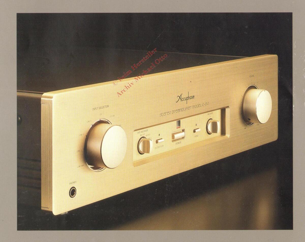
STEREO PREAMPLIFIER
● Ideal balanced line amplifier ● Complete mono construction with separate power supplies for left and right channel●Volume control with mirror-finish resistor elements assures sonic purity ● Logic-controlled relays allow short signal paths●Headphone amplifier optimized for best sound
Accuphase Is Now Chall the Digital
In the year 1986, when the Compact Disc had begun to gain true acceptance, Accuphase created a sensation by introducing the separate-type CD Player DP-80/DC-81. Some of its highlights were a D/A converter system developed by Accuphase and built with discrete components for unprecedented precision, as well as the use of optical links and optical isolators for internal wiring, to assure freedom from digital interference. The sound quality of this CD reproduction system has gained highest praise worldwide.
The discrete multi-bit converter was further upgraded to 20-bit precision in the L version which continues to be used as a reference CD player to this day.
However, progress never stops. Now, in the 10th year since the introduction of the CD, Accuphase opens yet another chapter in the advancement of D/A conversion technology. We proudly introduce the revolutionary MMB (Multiple, Multi-Bit) system. As the name implies, several 20-bit D/A converters are used in parallel (in the case of the DC-91 a full sixteen per channel), to provide hitherto unheard-of linearity and to reduce noise to the absolute theoretical limit.
The link between the CD transport and processor units of course employs the optical principle, but it goes far beyond conventional designs. While optical links have become rather common these days, all too often one finds inferior, simplified implementations that
HPC optical ultrahigh-speed link with data transfer rate of 150M BPS
do not realize the full performance potential of this principle. It goes without saying that for Accuphase, only the best will do, and to this end, we have developed the innovative HPC digital input/output circuitry. HPC stands for "High Performance Connection". For optical links, it adopts the ST format that supports a data transfer rate of up to 150 megabits per second. This is as much as 25 times more than the 6 megabits actually required for digital audio, thus providing an ample safety margin. For balanced connections, HPC uses highquality professional-standard links as employed for example in computer networks. This eliminates pulse distortion and jitter, resulting in drastically improved sound quality. Of course, EIAJ-standard optical and balanced connectors are also provided.
The CD Transport DP-90 features a laser pickup with an integrated RF amplifier, to guard against any kind of interference. The spindle, sled, focusing and tracking actuators, disk tray etc. are driven by balanced circuits to reduce internal noise that could interfere with the pickup output signal. The chassis is made from 8-mm solid aluminum capable of absorbing any kind of vibration arising either inside or outside the player. Top-notch mechanical as well as electrical design and construction assure highly precise restoration of the digital information.
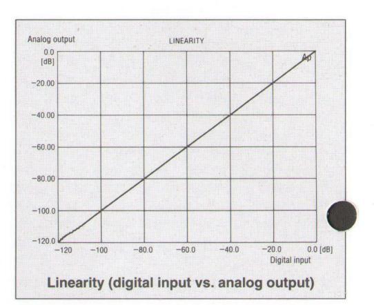
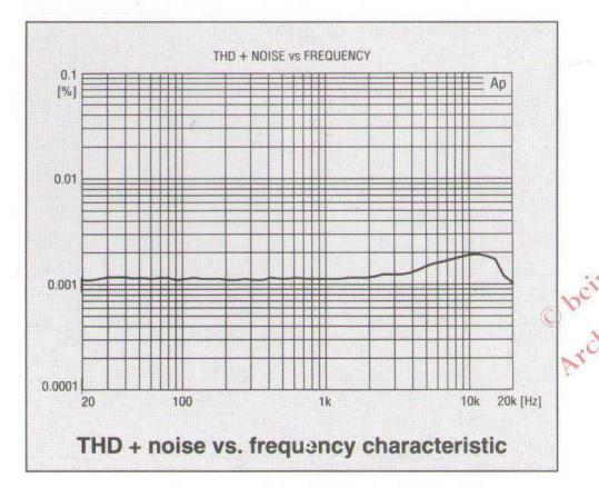
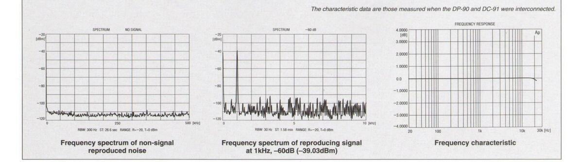
The Digital Processor DC-91 incorporates the MMB D/A converter system which redefines the state of the art. As can be seen from the graph, response of digital input versus analog output is absolutely linear from very high to extremely low levels. Distortion and noise are virtually absent. In all aspects, this processor attains the theoretical limit of performance.
The digital inputs are all equipped for 24-bit DAI (Digital Audio Interface) connections. Digital signal processing for functions such as signal attenuation and optional phase reversal is also performed at 24-bit resolution, and a 24-
bit digital output is provided to allow for future expansion.
The number of formats that permit digitar recording is currently on the increase, encompassing DCC, MD, DAT and recordable writeonce CDs. To accommodate such components, the DC-91 has two sets of digital inputs and outputs (each with optical and coaxial connectors), and one set of HPC balanced connectors for professional equipment. The unit therefore can also serve as digital control center, opening up new vistas for the enjoyment of superb digital sources.
enging to Revolutionize Audio World!
TECHNICAL NOTES
MMB Type D/A Conversion System
In a D/A converter that converts a digital signal into an analog signal, a conversion error (that is, a dif ference from an ideal conversion characteristic) wi always occur.
With the MMB Type D/A conversion system, this conversion error is minimized using a number of parallel-connected D/A converters, thus improving such characteristics as dynamic range, linearity, and the harmonic distortion factor.
Fig. 1 shows a block diagram of the MMB type D/A conversion system. The same digital signal is input to each D/A converter in the system and the conversion results of all the respective D/A converters are added together resulting in the total analog output from the system.
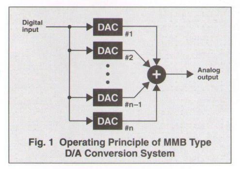
Because the outputs of all the respective converters will be added up, if an "n" number of converters are used, the total analog output will become a multiple of "n". However, how a conversion error occurs in the system differs from one converter to the other (as the error of one converter is a noncorrelated component independent of any other converters). Thus, the total analog output will not simply become a multiple of "n" but will be multiplied vn times. The output-to-noise ratio (a ratio between output level and noise level) with an "n" number of converters is 1/vn. In other words, because the conversion error becomes 1/vn, characteristics important to D/A converters such as dynamic range, linearity, and the harmonic distortion factor may be improved.
| No. of converters |
Output
level |
Noise
level |
Output level/
Noise level |
|
|---|---|---|---|---|
| 1 | 1 | 1 | ||
| 2 | 2 | 1.41 | 0.71 | |
| 3 | 3 | 1.73 | 0.58 | |
| : | : | • | • | |
| 16 | 16 | 4 | 0.25 | |
| : | : | • | : | |
| n | n | √n | 1/√n | |
With the DC-91, 16 20-bit resolution D/A converters operate in parallel with one another. The conversion error of the system becomes 0.25 (=1/√16) as compared with that when the number of converters is 1. As a result, conversion characteristics very close to those for the ideal 20-bit resolution converters have been implemented.
One great advantage of the MMB type D/A conversion system is that irrespective of the frequency
and level of a signal, improvements can be achieved at all frequencies and signal levels. Therefore, the problem of "linearity at minute signal levels", which has been considered to be a drawback of conventional multi-bit type D/A converters, can be solved at once.
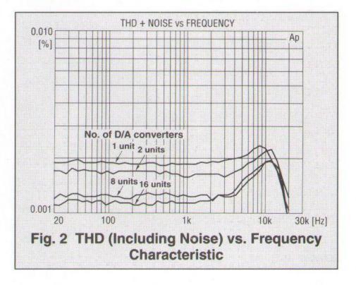
Fig. 2 shows the total harmonic distortion (including noise) vs. frequency characteristic curves when the number of parallel-connected D/A converters was changed between one and 16 units. It can be seen that the higher the number of converters the better the distortion factor.
Dither Signal
The digitization of the amplitude of an analog signal in A/D conversion is referred to as "quantization". When converting a large-level analog signal into a digital signal, the error of approximation in the quantization process (i.e., quantizing noise) cannot be heard as the error (quantizing noise) is hidden in the signal. However, if the level of an analog signal becomes smaller, the quantizing noise cannot be ignored for the analog signal. Because the quantizing noise in this case changes according to the signal level, it becomes audible detrimental noise.
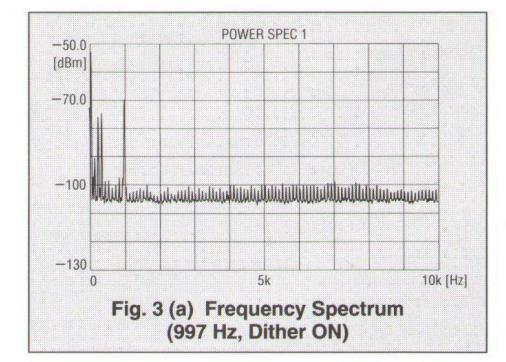
To avoid such a phenomenon, A/D conversion is carried out after mixing a sort of noise scattered over a wide frequency band and called a dither signal into the analog signal. (In general, the level of a dither signal is 1/2 to 1 of the digital signal step.) By doing so, the overall noise level increases that much by the level of the mixed dither signal as shown in Fig. 3 (a), but harmonic distortion due to the quantizing noise when the level of an analog signal is very small can be reduced. In other words, a dither signal is a noise signal that causes the quantizing noise to be scattered over a wide frequency band so that the noise becomes inaudible.
With the DC-91, before D/A conversion (not A/D conversion), a dither signal is mixed into the digital signal in digital arithmetic processing. (As shown in Fig. 3 (b), Dither OFF (not to mix a dither signal) may be specified.) In this case, the dither signal functions to scatter the arithmetic error caused by the digital filter over a wide frequency band.
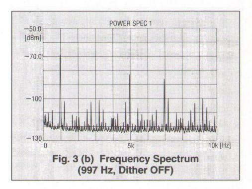
Fig. 4 shows the probability density curve of the dither signal adopted in the DC-91. This dither signal has a triangular probability density and its maximum amplitude value is ± 1/2 LSB of the input of a 20-bit resolution D/A converter (where LSB is the minimum unit of digital signal steps).
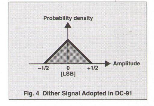
Unlike the signals of 16-bit audio data as for CD players, DAT recorders, and broadcasting by BS, the amplitude of the dither signal is extremely small (1/32 of the minimum step of data whose maximum amplitude is 16 bits). While ordinary music signals are being reproduced in the Playback mode, the effect of the dither signal cannot be exhibited too well. However, the dither signal works well when reproducing an initial digital record source or a disc containing music recorded at low levels.
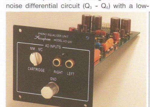
Dedicated Phono Equalizer Unit AD-250 (Option)
input stage uses two FETs (Q1, Q2) with high S/
N ratio, which is ideal for cartridges with high
output impedance. The MC input stage which
has to process small signals from cartridges
with low impedance, is configured as a low-
The C-250 in its standard configuration is designed as a pure line amplifier, mainly for and other digital media. However, many music lovers still own a valuable collection of analog records. For the needs of these audiophiles, the C-250 offers an attractive solution: simply by inserting the dedicated phono equalizer unit AD-250 into a special slot on the rear panel, the C-250 provides phono reproduction capabilities of the highest order.
The AD-250 features a gold-plated glass epoxy printed circuit board, and its circuit topology, as shown in Fig. 5, reflects the long experience of Accuphase in designing top-guality phono equalizers. Dedicated MM and MC input stages of the phono amplifier provide optimum conditions for each type of phono cartridge. The MM
features can be set on the printed circuit board before mounting the equalizer unit in the C-250.
MC input impedance is switchable between 10.
30 and 100 ohms and a subsonic filter cuts off
harmful low-frequency components. These
impedance NFB loop.
Guaranteed Spec
| equency Response |
BALANCED/UNBALANCED INPUT
20-20,000Hz +0 -0.2dB AD INPUT 20-20,000Hz ±0.2dB |
|||||
|---|---|---|---|---|---|---|
| otal Harmonic Distortion | 0.005% (for all inputs) | |||||
|
put Sensitivity,
put Impedance |
Input |
Sensitivity
Rated output 0.5 V output |
Input impedance | |||
| AD:MM | 8.0mV | 2.0mV | 47k Ω | |||
| AD:MC | 0.25mV | 0.063mV | 10 Q • 30 Q • 100 Q * | |||
| BALANCED | 252mV | 63mV | 40k Ω | |||
| UNBALANCED | 252mV | 63mV | 20k Ω | |||
|
MC input impedance set by internal DIP switches in
the AD-250 |
||||||
|
ated Output Level
nd Impedance |
BALANCED/UNBALANCED OUTPUT : 2.0V, 50 Ω
TAPE REC : 252mV, 200 Ω AD source |
|||||
| Suitable Impe | dance : 4-10 | onms | ||||
| N Ratio | Input terminal |
Input shorted, I
S/N ratio at |
HF-A weighting
rated output |
S/N ratio (EIA) | ||
| AD:MM | 95dB | 88dB | ||||
| AD:MC | 79 | dB | 85dB | |||
| BALANCED | 97dB | 96dB | ||||
| UNBALANCED | 119dB | 97dB | ||||
|
aximum Output Level
(THD 0.005%,) |
BALANCED/UNBALANCED OUTPUT : 7.0 V
TAPE REC : 7.0 V (AD source) |
|||||
|
aximum AD Input Level
(1 kHz, THD 0.005%) |
MM/INPUT
MC/INPUT |
: 250m
1
: 8m 1 |
||||
| inimum Load Impedance |
BALANCED OU
UNBALANCED OU TAPE REC |
TPUT: 600 ג
אדריין 10 געד: 10 געד: 10 ג 10 ג |
||||
| ain |
BALANCED/UNBALANCED INPUT → BALANCED/UNBALANCED OUTPUT : 18dE
AD MM INPUT → REC OUTPUT : 30dE AD MM INPUT → BALANCED/UNBALANCED OUTPUT : 48dE AD MC INPUT → REC OUTPUT : 60dE AD MC INPUT → BALANCED/UNBALANCED OUTPUT : 78dE |
|||||
| bsonic Filter Characteristics |
25Hz, -12dB/octave
(Set by internal DIP switches in AD-250) |
|||||
| ower Requirements |
100V, 120V, 220V, 230V. 240V, (Voltage as indicated or
rear panel) AC, 50/60Hz |
|||||
| ower Consumption | 9 watts | |||||
| aximum Dimensions |
475mm(18-7/10") width
140mm(5-1/2") height 401mm(15-4/5") depth. 414mm(16-3/10") depth(with AD-250) |
|||||
| eight |
13.8kg(30.4lbs.) net
13.9kg(30.6lbs.)(with AD-250) net 18.3kg(40.3lbs.)in shipping carton 18.4kg(40.5lbs.)(with AD-250)in shipping carton |
|||||
emote control principle: infrared pulse ower supply: 3V DC (IEC R03 batteries(size AAA)×2) imensions: 66mm (2-19/32 inches) width, 175mm (6-7/8 inches) height,
cuphase
*Specifications and design subject to change without notice for improvements


 Loading...