

Page 1
m Current feedback circuit topology provides outstanding high-
range phase characteristics m Six line amplifier units in tripleparallel dual MCS configuration m Fully modular unit amplifiers
with discrete circuitry m Tone control circuitry m Option boards
allow digital signal input and analog disc reproduction
Page 2
Optimum match for P-370 power amplifier This state-of-the-art
preamplifier features current feedback technology, six fully separate line
amp units in triple-parallel dual MCS configuration, and fully dual-mono
construction with separate power supplies. Option board allows digital
signal input for top-quality CD reproduction.
Accuphase preamplifiers implement advanced
technology such as current feedback and
balanced signal transmission, in order to
achieve optimum quality reproduction that is
true to the spirit of the music. This is the reason
why our products continue to enjoy such a high
reputation. The C-245 is a stereo control center
that fully represents Accuphase technological
expertise. As the model name indicates, the
amplifier stands in the tradition of the C-200/
P300 series that has been the mainstay of
the Accuphase product lineup since its
inception. An ideally matched power amplifier
is found in the model P-370, capable of
delivering an amazing 400 watts per channel
into an ultra-low-impedance load of 1 ohm.
The line amplifier circuits of the C-245 are
based on the current feedback principle, which
has consistently received high praise for sonic
excellence and top-notch performance. Three
line amplifier modules are used for each
channel, resulting in a total of six line amp
modules, arranged in a triple parallel MCS
(Multiple Circuit Summing) configuration. This
arrangement provides drastic improvements
in S/N ratio, distortion, and other important
performance parameters. All parts used in the
C-245 have been carefully selected on the
basis of extended listening tests. Features
such as tone controls and loudness
compensator allow precise fine tuning if
desired, and facilities for tape recorder
connection are also provided. In sound quality
and performance, the C-245 is a superbly
conceived top-notch product.
The possibility of installing option boards
further enhances flexibility. A Digital Input
Board using an MDS (Multiple Delta Sigma)
D/A converter can directly handle the digital
signal from a CD player or similar, for ultrapure music reproduction. A board for faithful
playback of analog records is also available.
Current feedback circuit topology prevents
high-range phase shifts and ensures
superb sound quality
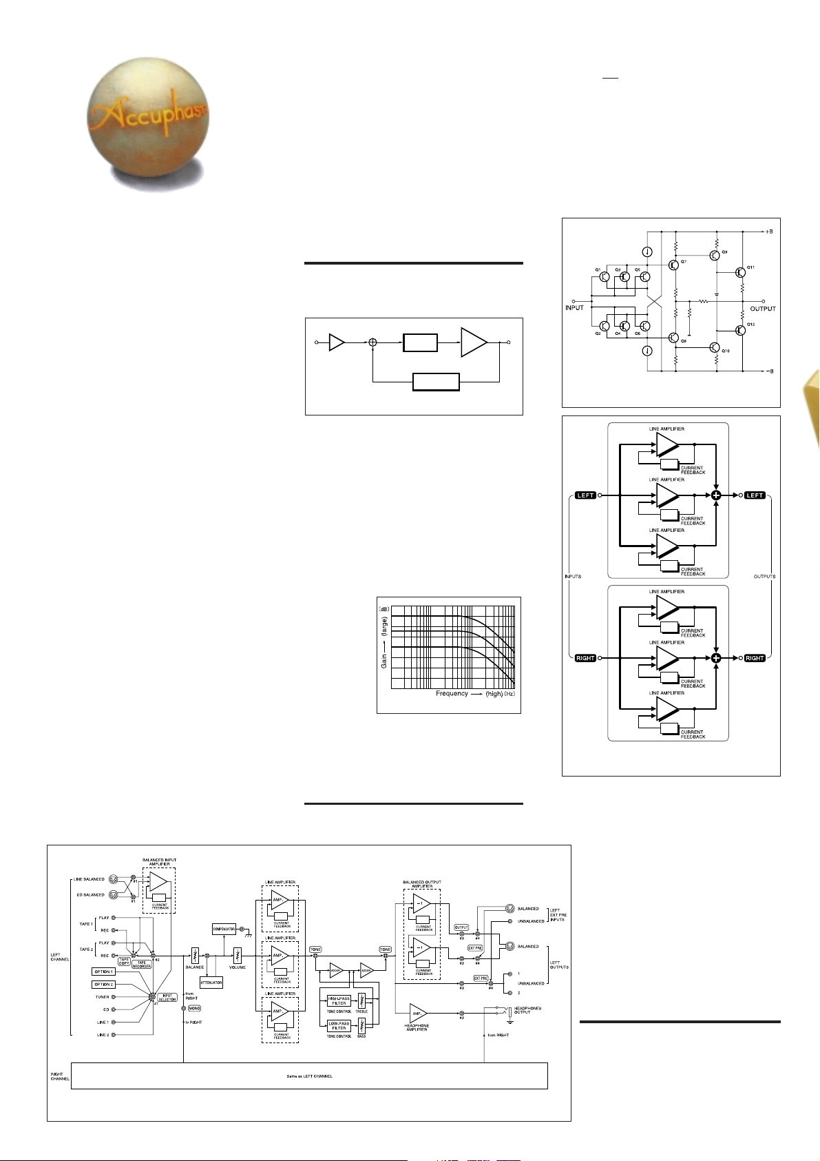
The C-245 uses the current feedback principle
for negative feedback. Figure 2 shows the
operating principle of this design.
Current adder
Input
Buffer
Fig. 2 Current feedback amplifier principle diagram
I-V
converter
Trans-impedance
amplifier
Current NFB
network
Amplifier
Output
At the input point of the feedback loop, the
impedance is kept low for current detection.
A trans-impedance amplifier converts the current into a voltage to be used as the feedback
signal. Since the impedance at the current
feedback point (current adder in Figure 2) is
very low, there is almost no phase shift. Phase
compensation therefore can be kept at a minimum. A minimal amount of NFB results in
maximum improvement of circuit parameters.
The result is excellent transient response and
superb sonic transparency, coupled with utterly natural
energy balance. Figure
3 shows frequency response for
different gain
settings of
the current
feedback am-
Fig. 3 Frequency response with current feedback
(Response remains uniform even when gain changes)
plifier. The graphs demonstrate that response
remains uniform over a wide range.
Six discrete line amplifiers in MCS
configuration designed for optimum sound
The line amp units of the C-245 (Figure 4)
Fig. 4 Line amplifier unit circuit diagram
(3 units are used in parallel connection per channel)
Fig. 5 Line amplifier (MCS circuit)
operation principle
employ a pure complementary push-pull
circuit topology. Hand-selected discrete parts
are used in parallel for minimum noise.
Six line amplifiers are connected in a triple
parallel MCS (Multiple Circuit Summing)
configuration developed by Accuphase.
By arranging three line amp units for each
channel in a parallel connection, the
performance advantages of each circuit
are added up, resulting in improved S/N
ratio, distortion and other vital
performance parameters. The overall
result is a stereo amplifier with superb
characteristics.
Fig. 1 C-245 block diagram
Balanced connection reliably blocks
induced noise
The longer the cable connections between
audio components, the higher is the
danger of external noise being introduced
into the signal path, which invariably leads
to sound quality degradation. The balanced
connection principle reliably prevents this
danger, by keeping the signal transfer
Page 3

n Supplied remote commander RC-20
Allows volume adjustment and source
switching.
n Line amplifiers and balanced input/
output amplifiers arranged on PCB
motherboard (total 10 modules)
completely free from any kind of
interference.
Modular construction keeps amplifier
circuits separate
The six line amplifiers and balanced output
amplifiers are housed in a total of 10 separate
modules neatly arranged on a motherboard.
The units are firmly secured with a frame
construction to prevent external vibrations
from affecting the sound.
Triple parallel unit amplifier
Complete mono construction with separate
transformers for left and right channels
Tone controls use summing
active filters for highest sound quality
The tone control circuitry in the C-245 was
specially designed with summing active filters
such as
found in
high-quality
graphic
equalizers.
Figure 6 illustrates
the operation principle of this
circuit. The
Tone control characteristics
flat signal is passed straight through, and only
when an adjustment is required, the characteristics are created at F1 and F2 and added to
Input
Output
the signal, thereby producing the desired
change. This design provides efficient control
without degrading signal purity.
Logic-controlled relays for signal switching
assure high sound quality and long-term
reliability
The use of logic-controlled relays at strategic
locations makes it possible to keep signal
paths extremely short. The relays used in the
C-245 are high-performance hermetically
sealed types as used in professional
communication applications. The contacts are
twin crossbar types plated with gold and silver
palladium alloy, for minimum contact
resistance and outstanding long-term
reliability.
The power supply of the C-245 employs a dualmono approach with separate power
transformers and filtering capacitors for the
two stereo channels. Each unit amplifier is
equipped with a wide-range low-impedance
voltage regulator to eliminate any possibility
of interference between stages.
Fig. 6 Tone control circuit diagram
(summing active filter type)
Sealed relays directly
connected to gold-plated input/output connectors
Page 4

Other features and functions
n Option board available for direct digital sig-
nal input for high-grade CD reproduction
n Option board available for analog record re-
production
n High-quality volume control. Supplied remote
commander for volume adjustment and
source switching.
n High carbon cast-iron insulator feet for high
sound quality
n Dedicated headphone amplifier for optimum
sound
n EXT PRE function permits use of external
preamplifier for playback
n Loudness compensator for enhanced bass
at low listening levels
Compensator response
Option Boards
Three types of option boards are available for the C-245: Digital Input Board DAC-10, Analog Input Board AD-10, and Line
Input Board LINE-10. Insert the desired board in a rear-panel
option board slot.
m The DAC-10 cannot be used in the models E-407, E-406V,
E-306V, E-211, C-265.
m The Analog Disc Input Board AD-9 and the Line Input Board
LINE-9 can also be used.
Option board shown in photo is DAC-10
Digital Input Board DAC-10
This board features an MDS (Multiple Delta Sigma)
D/A converter and has inputs for coaxial and optical
fiber connections.
It can accept the digital output signal from components such
as a CD player, MD recorder, DAT recorder, etc. (sampling
frequency range 32 - 96 kHz, 24 bits).
Analog Disc Input Board AD-10
This board contains a high-performance, high-gain
phono equalizer.
Internal DIP switches control MM/MC operation, MC input
impedance, and subsonic filter on/off.
Gain : 36 dB
MM
Input impedance : 47 kilohms
Gain : 62 dB
MC
Input impedance : 10/30/100 ohms
(selectable)
Line Input Board LINE-10
This option board provides an additional set of conventional
unbalanced line inputs which can be used to connect a CD
player, tuner, or other component with analog output.
n Front panel
n Rear panel
Option board
expansion slots
A INPUT SELECTOR
B Function LED indicators
C VOLUME Control
D PHONES Jack
E POWER Switch
F EXT PRE and output ON/OFF Switch
G BASS Control
H TREBLE Control
I TONE Controls ON/OFF Button
J COMP (Compensator) ON/OFF Button
K TAPE COPY Selector 1➞2 OFF 2➞1
L TAPE RECORDER Selector
REC OFF SOUCE 1 2
Remarks
★
This product is available in versions for 120/230 V AC. Make sure that the voltage shown on
the rear panel matches the AC line voltage in your area.
★
The shape of the AC inlet and plug of the supplied power cord depends on the voltage rating
and destination country.
M BALANCE Control
N STEREO/MONO Button
O Attenuator Button
P Line inputs
Q TAPE 1, 2 Play/Record Connectors
R OUTPUTS (Unbalanced)
S EXT PRE (External Preamplifier) input
(Unbalanced)
T CD/LINE INPUTS (BALANCED)
21
U OUTPUTS (Balanced)
22
U EXT PRE (External Preamplifier) Inputs
(Balanced)
23
U AC Power Supply Connector
★
GUARANTEED SPECIFICATIONS
[Guaranteed specifications are measured according to EIA standard RS-490.]
m Frequency Response BALANCED/UNBALANCED INPUT
m Total Harmonic Distortion (for all inputs) 0.005%
m Input Sensitivity, Input Impedance
Input
BALANCED
UNBALANCED
m Rated Output, BALANCED/UNBALANCED OUTPUT 2 V, 50 ohms
Output Impedance TAPE REC 252 mV, 200 ohms
m Signal-to-Noise Ratio
Input
BALANCED
UNBALANCED
m Maximum Output Level (0.005% THD, 20 - 20,000 Hz)
m Minimum Load Impedance
m Gain
BALANCED/UNBALANCED INPUT ➞ BALANCED / UNBALANCED OUTPUT
BALANCED/UNBALANCED INPUT ➞ REC OUTPUT
m Loudness Compensation +6 dB (100 Hz)
m Tone Controls Turnover frequency and adjustment range
★
m Attenuator -20 dB
m Headphones Jack Suitable impedance: 8 - 100 ohms
m Power Requirements AC 120 V / 230 V (Voltage as indicated on rear panel)
m Power Consumption 16 watts
m Maximum Dimensions Width 475 mm (18-11/16")
m Weight 16.8 kg (37.0 lbs) net
m Supplied Remote Commander RC-20
3 - 300,000 Hz +0, -3.0 dB
20 - 20,000 Hz +0, -0.2 dB
For rated output For 0.5 V output
Input shorted, IHF-A weighting
S/N ratio at rated input
Sensitivity
252 mV 63 mV 40 kΩ
252 mV 63 mV 20 kΩ
S/N ratio (EIA) Residual noise
108 dB 97 dB 1.0 µV
121 dB 97 dB 1.0 µV
BALANCED/UNBALANCED OUTPUT
TAPE REC : 5.0 V
BALANCED/UNBALANCED OUTPU
TAPE REC : 10 kilohms
BASS : 300 Hz ±10 dB (50 Hz)
TREBLE : 3 kHz ±10 dB (20 kHz)
50/60 Hz
Height 150 mm (5-7/8")
Depth 409 mm (16-1/8")
21.0 kg (46.3 lbs) in shipping carton
Remote control principle: Infrared pulse
Power supply : 3 V DC (IEC R6 batteries × 2)
Dimensions : 55 mm (W) x 194 (H) x 18 (D) mm
Weight : 100 g (including batteries)
Input impedance
: 5.0 V
T : 600 ohms
: 18 dB
: 0 dB
n Supplied accessories: • AC power cord
• Specifications and design subject to change without notice for improvements.
• Audio cable with plugs (1 m)
• Remote commander RC-20
K015Y PRINTED IN JAPAN 850-0123-00 (AD1)http://www.accuphase.com/
 Loading...