

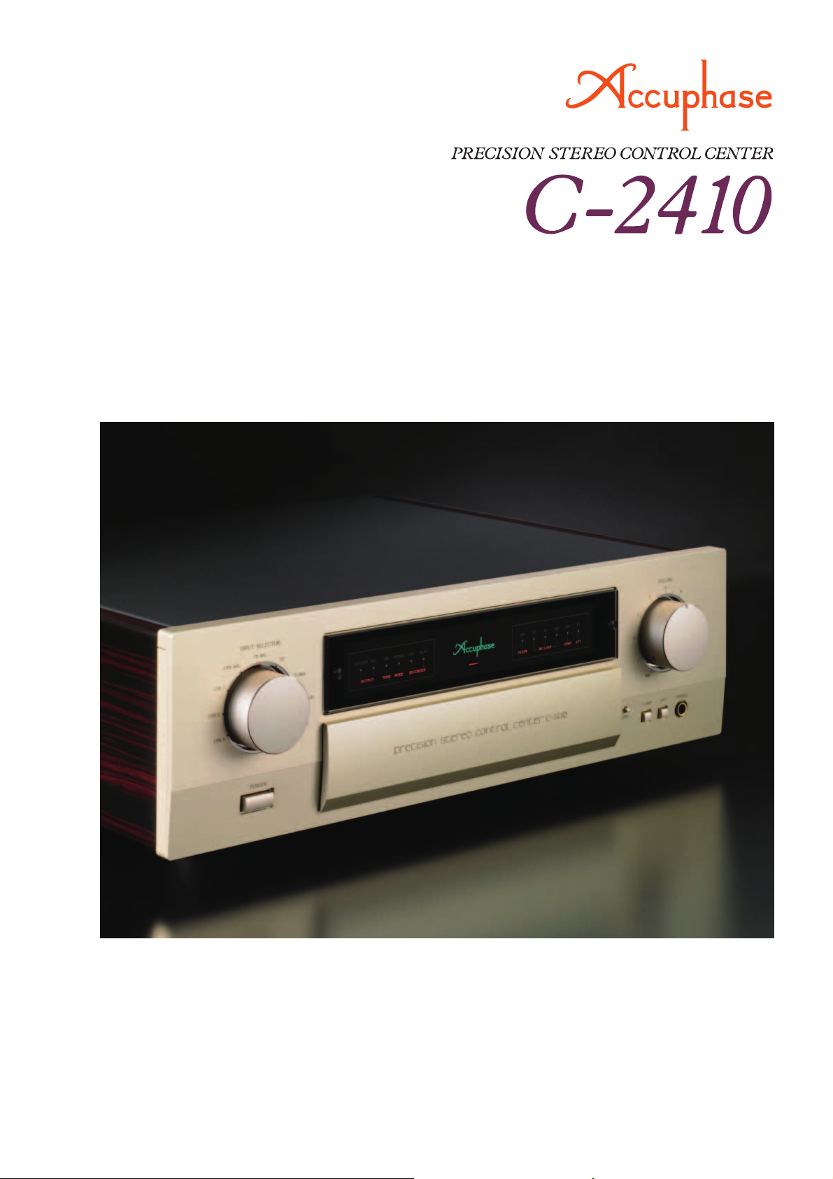
Page 1
● Revolutionary AAVA volume control ● Separate power transformers
for left and right channels ● Selectable preamp gain ● Fully modular
construction with individual left/right amplifi er units on motherboard
● Logic-controlled relays for shortest signal paths ● Independent phase
selection for each input position ● Optional phono equalizer unit allows
analog record playback ● Side panels with elegant persimmons wood fi nish
Page 2
A stereo control center of the next generation – Further evolved
AAVA type volume control. Complete dual mono construction
with separate AAVA and other amplifi cation modules and separate power supplies. Overall preamp gain selection and independent phase selection for each input position. Optional phono
equalizer unit allows high-quality playback of analog records.
The C-2410 inherits the superb design technology of
the C-2810, including the improved AAVA (Accuphase
Analog Vari-gain Amplifi er) volume control with similar
specs and confi guration. AAVA is a revolutionary
concept that takes a radically different approach
from conventional volume controls. The result is
high performance and sound quality far exceeding
conventional designs.
AAVA does not use variable resistors, which brings
a number of distinct advantages:
response does not change, regardless of the volume
setting.
S/N ratio is outstanding. 3 Distortion is
2
reduced to an absolute minimum.
left/right level differences (tracking error).
channel crosstalk is minimized. Another benefi t of
AAVA is the fact that only highly reliable electronic
components are used. Mechanical wear ceases
to be a problem, ensuring that the outstanding
performance and sound quality of the amplifi er will
remain undiminished for many years to come. Unlike
conventional digital volume controls, AAVA operates
through purely analog processing. The operating feel
using a volume knob on the front panel also is exactly
the same as with other high-end stereo components.
The power supply section of the C-2410 employs
two separate transformers, one for each channel.
Filtering capacitors and all other parts of the power
supply are duplicated for left and right. What's more,
the AAVA circuitry, balanced output circuits, and other
unit amplifi ers are also entirely separate for the two
channels, arranged on a high-quality motherboard.
This fully monaural construction prevents unwanted
crosstalk and interaction both on the electrical and the
physical plane.
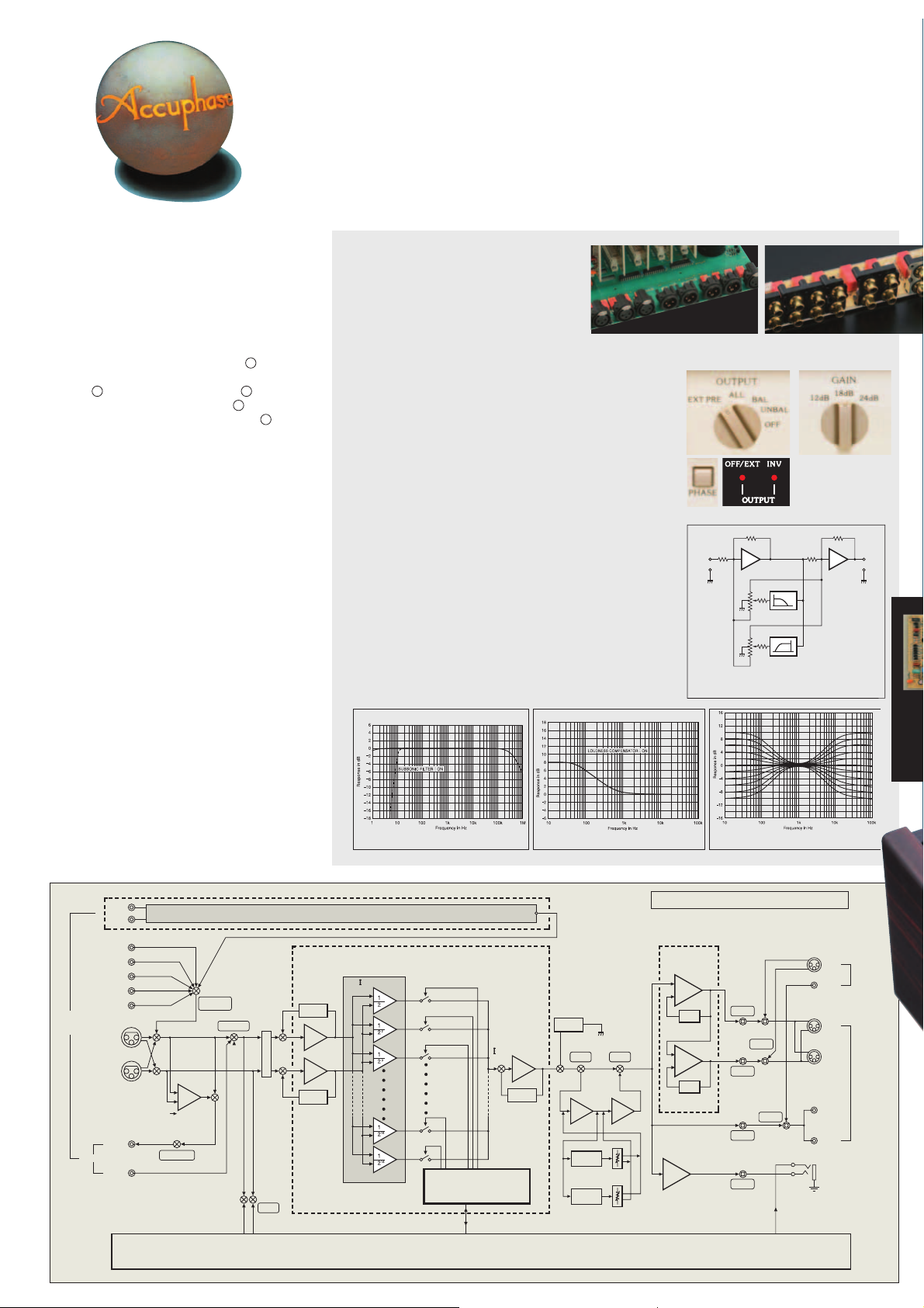
As can be expected of a control center, the
C-2410 offers a full complement of balanced and
unbalanced input and output connectors. Flexibility is
further enhanced by features such as tone controls,
loudness compensation, recorder functions, subsonic
fi lter, overall gain selection, EXT PRE connectors
for combination with another preamplifi er, and
independent phase selection for each input position.
An optional phono equalizer unit is available for
playback of analog records with ultimate sound
quality.
Frequency
1
There are no
4
Left/right
5
■ Logic-controlled relays assure high
sound quality and long-term reliability.
The strategically placed relays of the C-2410
prevent any signal degradation that could
occur if the signal has to travel a long way
for input and output connection and function
switching. Optimum signal fl ow is maintained
at all times.
■
EXT PRE function allows use of external preamplifi er.
■ Selectable preamp gain.
The overall gain of the preamplifi er can be set to 12 dB, 18 dB,
or 24 dB.
■ Independent phase selection for each input position.
The selected phase setting is memorized for each input position
separately. The on/off status of a LED indicator shows the
respective setting.
■ Dedicated headphone amplifier optimized for sound
quality.
■ Versatile array of balanced and unbalanced input and
output connectors.
■ Aluminum-base side panels with persimmons wood fi nish
provide a striking visual appeal.
■ Tone controls using summing active fi lters for highest
sound quality.
■ More versatile features:
● Provisions for recording and playback with two recorders
● Subsonic fi lter removes ultra low frequency noise
● Loudness compensator augments bass impact at low listening
volume
● Attenuator (-20 dB)
Frequency response/subsonic fi lter
response characteristics
Loudness compensator characteristics
Balanced input and
output connectors
Input
-
A1
VR1
VR2
Principle of tone control circuitry
(Summing active fi lter type)
Unbalanced input and
EXT PRE function
and phase selector
button, with LED
indicators
F1
F2
Tone control characteristics
output connectors
Gain selector
Output
-
A2
LEFT
CHANNEL
INPUTS
CD-BAL
LINE-BAL
RECORDER
RIGHT
CHANNEL
AD 1
AD 2
TUNER
LINE 1
LINE 2
LINE 3
REC
PLAY
CD
BALANCED UNBALANCED
R
AMPLIFIE
RECORDER
OPTION: Phono Equalizer Unit AD-2800
(Accuphase Analog Vari-gain Amplifier)
V- I Converter
INPUT
SELECTOR
RECORDER
PHASE
MODE
SUBSONIC
FILTER
BUFFER
BUFFER
SUBSONIC
FILTER
AAVA
CPU
Same as LEFT CHANNEL
I- V Converter
Volume
Balance
Attenuator
Block Diagram of C-2410
Balanced
Output
Amplifier
-1
COMPENSATOR
TONETONE
GAIN
ADDER ADDER
HIGH-PASS
FILTER
TONE CONTROL TREBLE
LOW-PASS
FILTER
TONE CONTROL BASS
CURRENT
FEEDBACK
CURRENT
FEEDBACK
HEADPHONE
AMPLIFIER
-1
OUTPUT
EXT PRE
OUTPUT
OUTPUT
OUTPUT
EXT PRE
from RIGHT channel
BALANCED
UNBALANCED
BALANCED
UNBALANCED
1
2
1
2
HEADPHONE
OUTPUT
LEFT
CHANNEL
EXT PRE
INPUTS
LEFT
CHANNEL
OUTPUTS
Page 3

AAVA (Accuphase Analog Vari-gain Amplifi er) volume control
AAVA is a radically different volume control principle that does not use variable resistors and provides top-notch performance and sound
quality. Because the music signal does not pass through variable resistors, it is not affected by changes in impedance. This means that high
signal-to-noise ratio and low distortion of the signal are maintained at any volume control setting.
Volume control resolution.
■
AAVA adjusts the listening volume by means of 16 weighted V-I
converter amplifi ers which are controlled by current switches. The
number of possible volume steps set by the combination of these
converter amplifi ers is 2 to the power of 16 = 65,536.
AAVA ensures high S/N ratio and uniform frequency
■
response.
With conventional volume controls, the impedance increases
signifi cantly at settings that correspond to normal listening levels,
thereby leading to increased noise. With AAVA, there is no change
in impedance and consequently no deterioration of S/N ratio.
Frequency response also remains totally uniform. Changing the
volume with AAVA does not mean introducing noise or detracting
from the high performance of the amplifi er.
16 current switches (65,536
possible combinations)
Input music signal
No more left/right tracking differences or crosstalk.
■
Because AAVA is an electronic circuit employing fi xed-value
resistors, there is virtually no left/right tracking error also at low
volume levels. Since channels can be kept separate, crosstalk
also does not present a problem.
Simple circuit confi guration.
■
AAVA unifi es the amplifi er and volume control functions, resulting
in a circuit that is electrically very simple. Long-term reliability is
excellent, with performance and sound quality that will remain
unchanged also after prolonged use.
AAVA means analog processing.
■
The AAVA circuit converts the music signal from a voltage into a
current, switches gain by means of current switches, and then
reconverts the current into a voltage. The entire process is carried
Operation principle
of AAVA in C-2410
Reconversion of
current into voltage
Current
values are
added
out in the analog domain.
Same operation feel as a conventional high-quality
■
volume control.
The volume control knob position is detected by a dedicated CPU
which in turn selects the current switches for AAVA operation.
Operating the knob therefore feels exactly the same as with a
conventional control, and as before, operation via the remote
commander is also possible.
Attenuator and balance control also implemented by
■
AAVA .
The functions of the attenuator and the left/right balance control
are covered by the AAVA circuit as well, eliminating the need for
additional circuit stages. Keeping the confi guration simple helps
to maintain high performance and sonic purity.
AAVA operation principle
The music signal is converted into 16 types of weighted
current by V-I (voltage - current) converting amplifi ers [1/2,
2
1/2
, ... 1/215, 1/216]. The 16 currents are turned on or off by
16 current switches, and the combination of switch settings
determines the overall volume. The switching operation is
controlled by a CPU according to the position of the volume
control knob. The combined signal current forms a variable
gain circuit that adjusts the volume. Finally, the combined
current is converted back into a voltage by an I-V (current
- voltage) converter.
Conversion into current with 16
weighting stages (1/2 - 1/216)
CPU detects position of volume knob and operates
current on/off switches according to knob position
AAVA circuitry is implemented
in the form of unit amplifi ers
arranged on a motherboard
and kept separate for left
and right channels. Modules
include input buffers, 16
V-I converters + current
switches, current adding
circuitry, and I-V
converters.
Volume knob is turned and
position is detected
Supplied remote
■
commander RC-200
provides access to
volume control, input
source selection, and
other functions.
Page 4

Dedicated Phono Equalizer Unit AD-2800
Analog records can be reproduced by installing the dedicated phono equalizer unit AD-2800 in a rear-panel slot. The
AD-2800 uses printed circuit boards made from Tefl on material (glass fl uorocarbon resin substrate) and is housed in
a sturdy aluminum case for complete protection against any external interference. The shortest possible connection
between input and amplifi cation circuits ensures outstanding S/N ratio, and highly reliable DIN connectors are used
for the link to the main unit.
✽ The AD-2800 can also be used in the Accuphase models C-2810, C-2800, C-2400, C-290 and C-290V.
✽ The phono equalizer units AD-290 and AD-290V designed for the Accuphase models C-290 and C-290V can also be used in the C-2410.
AD-2800 installation
Front Panel
■
Rear Panel
■
Expansion slot
for AD-2800
Input selector
Function indicator LEDs
Volume controls
Power switch
Output selector
Bass/treble controls
Phase selector button
Recorder buttons ON, PLAY
Tone control on/off button
Stereo/mono selector button
Subsonic fi lter
MC cartridge load impedance selector button
AD gain selector
Gain selector 12dB 18dB 24dB
Balance control
Input
Circuit diagram of phono equalizer unit
AD-2800 (one channel)
Pressing this button
opens the sub panel
+
Loudness compensator button
Attenuator button
Headphone jack
Line input connectors
TUNER CD LINE 1,2,3
Recorder playback/recording connectors
Unbalanced output connectors (2 sets)
External preamplifi er input connectors
(unbalanced)
CD/LINE balanced input connectors
1
Ground 2 Inverted (–)
3
Non-inverted (+)
Balanced output connectors (2 sets)
External preamplifi er input connectors (balanced)
AC power supply connector
+
Output
AD gain selector and MC LOAD button
●
on front panel of C-2410 facilitate
settings for phono playback.
Equalizer
elements
DC servo amplifi er
AD gain selector
MC LOAD selector button and LED
Guaranteed Specifi cations
✽
Guaranteed specifi cations are measured according to EIA standard RS-490. AD stands for “Analog Disc”.
✽ Specifi cations are shown for phono equalizer unit AD-2800 installed.
● Frequency Response
20 - 20,000 Hz +0,
AD INPUT [MM/36dB, MC]: 20 - 20,000 Hz ±0.2 dB
AD INPUT [MM/30dB]: 20 - 20,000 Hz ±0.3 dB
● Total Harmonic Distortion (for all inputs) 0.005%
● Input Sensitivity, Input Impedance
Input
AD:MM/30 dB
AD:MM/36 dB
AD:MC/62 dB
AD:MC/68 dB
BALANCED/UNBALANCED 252 mV
● Rated Output Voltage,
Output Impedance RECORDER REC (with AD input): 252 mV, 200 ohms
● S/N Ratio (gain selector: 18 dB)
Input
AD:MM/30 dB
AD:MM/36 dB
AD:MC/62 dB
AD:MC/68 dB
BALANCED/UNBALANCED
● Maximum Output Level
(0.005% THD, 20 - 20,000 Hz) RECORDER REC (with AD input)
●
LINE maximum input level
● Maximum AD Input Level MM [30/36 dB] INPUT: 300/150 mV
(0.005% THD) MC [62/68 dB] INPUT: 7.5/3.75 mV
●
Minimum Load Impedance BALANCED/ UNBALANCED OUTPUT:
RECORDER REC: 10 kilohms
●
Gain (gain selector: 18 dB)
BALANCED/ UNBALANCED INPUT BALANCED/ UNBALANCED OUTPUT: 18 dB
UNBALANCED INPUT REC OUTPUT: 0 dB
AD (MM: 30/36 dB) INPUT BALANCED UNBALANCED OUTPUT: 48/54 dB
AD (MM: 30/36 dB) INPUT REC OUTPUT: 30/36 dB
AD (MC: 62/68 dB) INPUT BALANCED/ UNBALANCED OUTPUT: 80/86 dB
AD (MC: 62/68 dB) INPUT REC OUTPUT: 62/68 dB
✽ Gain can be set to 12/18/24 dB
●
Loudness Compensation
● Subsonic Filter 10 Hz: –18 dB/octave
● Attenuator –20 dB
● Headphone Jack Suitable impedance: 8-100 ohms
● Power Requirements AC120 V/230 V, 50/60 Hz (Voltage as indicated on rear panel)
● Power Consumption 33 watts
● Maximum Dimensions Width: 465 mm (18-5/16”)
Height: 150 mm (5-7/8”)
Depth: 409 mm (16-1/8”)
(Depth with AD-2800 installed: 414 mm)
● Mass 18.9 kg (41.7 lbs) net (19.8 kg with AD-2800 installed)
24.0 kg (52.9 lbs) in shipping carton
BALANCED/UNBALANCED INPUT: 3 - 200,000 Hz +0, –3.0 dB
For rated output For 0.5 V output
BALANCED/ UNBALANCED OUTPUT: 2 V, 50 ohms
BALANCED/UNBALANCED OUTPUT:
BALANCED/ UNBALANCED INPUT: 6.0 V
+6 dB (100 Hz)
Sensitivity
8.0 mV
4.0 mV
0.2 mV
0.1 mV
Input shorted, IHF-A weighting
S/N ratio at rated output
95 dB
89 dB
80 dB
75 dB
109 dB
2.0 mV 47 kΩ
1.0 mV 47 kΩ
0.05 mV
0.025 mV
63 mV 40 kΩ/20 kΩ
: 6.0 V
Input impedance
10/30/100 Ω, switchable
10/30/100 Ω, switchable
S/N ratio (EIA)
7.0 V
600 ohms
–
0.2 dB
91 dB
92 dB
87.5 dB
88.5 dB
107 dB
Remarks
+
This product is available in versions for 120/230 V AC. Make sure that the voltage shown on the rear panel matches the AC line voltage in your area.
+
The shape of the AC inlet and plug of the supplied power cord depends on the voltage rating and destination country.
Supplied accessories:
■
● AC power cord
Audio cable with plugs (1 m)
●
Remote commander RC-200
●
Cleaning cloth
●
●
Specifi cations and design subject to change without notice for improvements.
http://www.accuphase.com
C0705Y PRINTED IN JAPAN 851-0165-00 (AD1)
 Loading...