

Page 1
m Revolutionary AAVA volume control m Fully modular
construction with individual left/right amplifier units arranged on
motherboard m Separate power transformers and filtering
capacitors for left and right channels m Logic-controlled relays
for shortest signal paths m High quality tone controls m Option
board slots allow digital signal input and analog record playback
Page 2
Innovative AAVA type volume control Adjusts listening level without
deterioration in S/N ratio or distortion. Dual mono construction with two power
transformers and separate modular AAVA amplifiers for left and right channels
mounted on motherboard. Option board slots provide support for digital input
signals and high-grade analog record playback.
The C-2000 inherits the design technology of
the Accuphase C-2800 and C-2400, featuring
the same AAVA type volume control. AAVA
(Accuphase Analog Vari-gain Amplifier) is an
innovative concept that differs radically from
conventional variable-resistor type volume
controls. It tackles one of the most important
aspects of a preamplifier, namely how it handles
listening level adjustment.
In AAVA, amplification and volume control are
fully unified, eliminating all mechanical contact
points. Pure analog processing ensures
optimum performance and superb sound. Doing
away with the variable resistor in the signal path
has numerous advantages and brings the
amplifier a significant step closer to absolute
purity in signal transmission. Another benefit of
AAVA is that it is configured only with highly
reliable semiconductor components. This
assures that performance and sound quality will
remain undiminished for many years to come.
The large volume knob on the front panel
employs a position detection method that
combines superb precision with a smooth
conventional feel.
The power transformer, filtering capacitors and
all other parts of the power supply are duplicated
for the left and right channel. What's more, all
unit amplifiers such as for line input, balanced
output, and AAVA are also entirely separate for
the two channels, arranged on a high-quality
motherboard. This fully monophonic construction
prevents unwanted interaction both on the
electrical and the physical plane.
The line amplifier with integrated volume control
is a major aspect of the C-2000, but there are
also a host of other attractive features in this
superb analog preamplifier. Tone controls and
loudness compensator allow fine tuning of the
sound. Tape recorder and copying facilities as
well as an EXT PRE function provide
connection flexibility. A range of option boards
allows the amplifier to handle digital input
signals and to realize high-grade playback of
analog records.
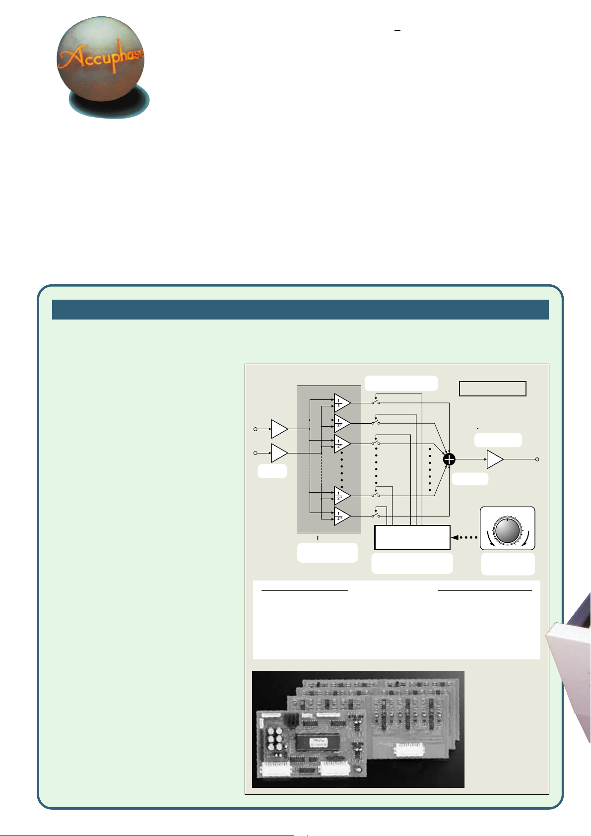
AAVA (Accuphase Analog Vari-gain Amplifier) volume control
The newly developed volume control called AAVA (Accuphase Analog Vari-gain Amplifier) is totally different from conventional controls using
resistors. Because the music signal does not pass through variable resistors, it is not affected by changes in impedance. This means that high
signal-to-noise ratio and low distortion of the signal are maintained. The volume can be adjusted without any deterioration in sound quality.
nn
n Volume control resolution
nn
AAVA adjusts the listening volume by means of 16 current
switches which are operated by 16 weighted V-I converter
amplifiers. The number of possible volume steps set by
the combination of these converter amplifiers is 2 to the
power of 16 = 65,536.
nn
n AAVA maintains high S/N ratio and unchanged
nn
frequency response
With conventional volume controls, the impedance
increases significantly at settings that correspond to normal
listening levels, thereby leading to increased noise.
Because there is no change in impedance with AAVA, there
is no deterioration of S/N ratio, and frequency response
also is not affected. Adjusting the volume with AAVA does
not mean introducing noise. High S/N ratio is maintained,
and there is no alteration of sound quality.
nn
n No more left/right tracking differences or crosstalk
nn
Because AAVA is an electronic circuit employing fixedvalue resistors, there is virtually no left/right tracking error
also at low volume levels. Since channels can be kept
separate, crosstalk also does not present a problem.
nn
n Simple circuit configuration
nn
AAVA unifies the amplifier and volume control functions,
resulting in a circuit that is electrically very simple. Longterm reliability is excellent, with performance and sound
quality that will remain unchanged also after prolonged
use.
nn
n AAVA means analog processing
nn
The AAVA circuit converts the music signal from a voltage
into a current, switches gain by means of current switches,
and then reconverts the current into a voltage. The entire
process is carried out in the analog domain.
nn
n Same operation feel as a conventional high-quality
nn
volume control
The volume control knob position is detected by a
dedicated CPU which in turn selects the current switches
for AAVA operation. Operating the knob therefore feels
exactly the same as with a conventional control, and as
before, operation via the remote commander is also
possible.
nn
n Attenuator and balance control also implemented by
nn
AAVA
The functions of the attenuator and the left/right balance
control are covered by the AAVA circuit as well, eliminating
the need for additional circuit stages. Keeping the
configuration simple helps to maintain high performance
and sonic purity.
BUFFER
INPUT
BUFFER
Input music
signal
V- I Converter
Conversion into current
with 16 weighting stages
(1/2 - 1/216)
AAVA operates by feeding the music signal to a V-I (voltage - current) converting amplifier
where it is weighted in 16 steps [1/2, 1/2
on or off by 16 current switches, and the combination of switch settings determines the
overall volume. The switching operation is controlled by a CPU according to the position of
the volume control knob. The combined signal current forms a variable gain circuit that
adjusts the volume. Finally, the combined current is converted back into a voltage by an
I-V (current - voltage) converter.
16 current switches
(65,536 possible combinations)
Volume
Balance
CPU
Attenuator
CPU detects position of volume knob
and operates current on/off switches
according to knob position
AAVA operation
2,
... 1/215, 1/216]. The 16 current steps are turned
AAVA principle
Current values
are added
Modular AAVA unit contains
input buffer, 16 V-I converter
amps and current switches,
current adder, I-V converter
amp, and other circuitry on
three boards, plus a CPU for
AAVA control. Modules are
installed separately for left/
right channel on a motherboard.
I-V Converter
Reconversion of
current into voltage
VOLUME
5
46
37
28
19
MIN MAX
Volume knob is
turned and position is
detected
OUTPUT
Page 3

Logic-controlled relays assure high sound
quality and long-term reliability
The C-2000 offers a host of input and output
connectors and functions. Strategically placed
relays allow straight and short signal paths, to
prevent degradation that could occur if the signal
had to travel long distances for connection and
function switching.
Dual mono construction with separate power
transformers and separate board-mounted
unit amplifiers for left/right
The input buffer, AAVA circuit, balanced output
and other amplifier circuitry are configured as
five separate units for each channel, arranged
neatly on a motherboard. Power transformers and
smoothing capacitors are also separate for the
two stereo channels. This thorough dual
monophonic approach assures total freedom
from unwanted mutual interaction.
Tone controls use summing active filters for
highest sound quality
The tone control circuitry in the C-2000 uses
summing active filters. The illustration below shows
the operation principle of this circuit. The flat signal
is passed straight through, and only when an
adjustment is required, the characteristics are
created at F
1 and F2 and added to the signal,
thereby producing the desired change. This design
–
A
Input
Tone control circuit principle
(using summing active filters)
1
F
1
VR
1
F
2
VR
2
–
A
2
Output
provides efficient control without degrading signal
purity. The turnover frequency for the bass control
(max. ±8 dB) can be switched between 40 and
100 Hz, and that for the treble control (max. ±8
dB) between 8 kHz and 20 kHz.
16
BASS TREBLE
12
8
4
0
Response in dB
–
4
–
8
–
12
–
16
10 100 1k 10k 100k
100Hz
40Hz 20kHz
Frequency in Hz
Tone control characteristics
8kHz
n Supplied remote commander RC-20
Allows volume control
and input source
selection.
Page 4

Other features and functions
nn
n Flexible input/output configuration
nn
nn
n Dedicated headphone amplifier optimized for
nn
high sound quality
nn
n EXT PRE function allows use of external
nn
preamplifier
nn
n Option board slots allow digital signal input and
nn
playback of analog records
nn
n Supplied remote commander with volume
nn
control function
nn
n Versatile features:
nn
• Recording/playback/monitoring facilities for 2
recorders with copy function
• Phase selector
• Attenuator
• Loudness compensator for rich bass at low levels
LOUDNESS COMPENSATOR : ON
Option Boards
Three types of option boards are available for the
C-2000: Digital Input Board DAC-10, Analog Disc Input
Board AD-10, and Line Input Board LINE-10. Insert the
desired board in a rear-panel option board slot.
• You can also install two identical boards.
• The Analog Disc Input Board AD-9 and the Line Input
Board LINE-9 can also be used.
• The DAC-10 cannot be used in the models E-407,
E-406V, E-306V, E-211, and C-265.
Digital Input Board DAC-10
This board features an MDS (Multiple Delta Sigma)
D/A converter. It can accept the digital output signal
from components such as a CD player, MD recorder,
DAT recorder, etc. (sampling frequency range 32 - 96
kHz, 24 bits) for high-grade music reproduction.
• Inputs for coaxial and optical fiber connections are
provided.
Analog Disc Input Board AD-10
This board contains a high-performance, high-gain
phono equalizer.
• Internal DIP switches control MM/MC operation, MC input
impedance, and subsonic filter on/off.
Gain: 36 dB
MM
Input impedance: 47 kilohms
Gain: 62 dB
MC
Input impedance:
10/30/100 ohms (selectable)
Response in dB
Compensator characteristics
n n
n Front panel
n n
n n
n Rear panel
n n
Option board slots
A
Input selector
LINE 2 LINE 1 LINE-BAL CD-BAL CD
TUNER OPTION 1 OPTION 2
B
Function LED indicators
C
Volume control
D
Power switch
E
Output selector
EXT PRE ALL BAL UNBAL OFF
F
BASS and TREBLE controls
G
Phase selector button
H
Tone control buttons
ON/OFF 40/100 Hz 8 kHz/20 kHz
I
Stereo/mono selector button
J
Loudness compensator button
K
Copy selector
1➞2 OFF 2➞1
Remarks
★
This product is available in versions for 120/230 V AC. Make sure that the voltage shown on the rear
panel matches the AC line voltage in your area.
★
The shape of the AC inlet and plug of the supplied power cord depends on the voltage rating and
destination country.
Frequency in Hz
Photograph shows an example of option board installation.
L
Recorder selector
REC OFF SOURCE 1 2
M
Balance control
N
Headphone jack
O
Attenuator button
P
Line input connectors TUNER CD LINE 1,2
Q
Recorder playback/recording connectors
R
Unbalanced output connectors (2 sets)
S
External preamplifier input connectors
(unbalanced)
T
CD/LINE balanced input connectors
a Ground b Inverted (–)
c Non-inverted (+)
21
U
Balanced output connectors
22
U
External preamplifier input connectors (balanced)
23
U
AC power supply connector
★
Line Input Board LINE-10
This option board provides an additional set of
AD-10
DAC-10
conventional unbalanced line inputs which can be used
to connect a CD player, tuner, or other component with
analog outputs.
GUARANTEED SPECIFICATIONS
[Guaranteed specifications are measured according to EIA standard RS-490.]
m Frequency Response BALANCED/UNBALANCED INPUT
m Total Harmonic Distortion 0.005% (for all inputs)
m Input Sensitivity, Input Impedance
Input
BALANCED 252 mV 63 mV 40 kΩ
UNBALANCED 252 mV 63 mV 20 kΩ
m Rated Output Voltage,
Output Impedance RECORDER REC: 252 mV, 200 ohms
m S/N Ratio
Input
BALANCED 108 dB 107 dB
UNBALANCED 108 dB 107 dB
m Maximum Output Level (0.005% THD, 20 - 20,000 Hz)
m Minimum Load Impedance BALANCED/UNBALANCED OUTPUT: 600 ohms
m Gain
BALANCED/UNBALANCED INPUT ➞ BALANCED/UNBALANCED OUTPUT:
BALANCED/UNBALANCED INPUT ➞ REC OUTPUT:
★
m Tone Controls Turnover frequeAncy and adjustment range
m Loudness Compensation +6 dB (100 Hz)
m Attenuator –20 dB
m Headphone Jack Suitable impedance: 8 - 100 ohms
m Power Requirements AC 120 V/230 V, 50/60 Hz
m Power Consumption 30 Watts
m Maximum Dimensions Width 465 mm (18-11/16")
m Mass 16.2 kg (35.7 lbs) net
m Supplied Remote Commander RC-20
Remote control principle: Infrared pulse
Power supply: 3 V DC (IEC R6 batteries × 2)
Maximum dimensions: 55 mm (W) × 194 (H) × 18 (D) mm
Mass: 100 g (including batteries)
03 - 200,000 Hz +0, –3.0 dB
20 - 20,000 Hz +0, –0.2 dB
For rated output For 0.5 V output
Sensitivity
BALANCED/UNBALANCED OUTPUT:
Input shorted (A weighting)
S/N ratio at rated output
BALANCED/UNBALANCED OUTPUT: 7.0 V
RECORDER REC: 6.0 V
RECORDER REC: 10 kilohms
BASS: 40/100 Hz switchable, ±8 dB
TREBLE: 8 kHz/20 kHz switchable, ±8 dB
(Voltage as indicated on rear panel)
Height 150 mm (6-3/4")
Depth 405 mm (16-5/8")
20.0 kg (44.1 lbs) in shipping carton
impedance
2 V, 50 ohms
EIA S/N
18 dB
10 dB
Input
n Supplied accessories: • AC power cord
• Audio cables with RCA-type plugs (1 m)
• Remote Commander RC-20
• Specifications and design subject to change without notice for improvements.
F0405Y PRINTED IN JAPAN 851-0139-00 (AD1)http://www.accuphase.com/
 Loading...