

Page 1
m Pure Class A operation delivers quality power: 60 watts × 2 into 8 ohms
m Power MOS-FET output stage features 10-parallel push-pull configuration
m Input circuitry with MCS topology m Current feedback design combines
superb sound with total operation stability m Bridged mode allows use as a
monaural amplifier m Massive “Super Ring” toroidal transformer rated for 1 kVA
m Dual-function power meters show digital readout or bar graph display
Page 2
Aiming for the ne plus ultra Experience the peerless sound of pure class A
and MOS-FETs. Input stage with MCS topology assures impeccable
performance in all aspects with minimum noise and distortion. 10-parallel pushpull power MOS-FETs operating in pure class A, and power supply with
massive 1 kVA toroidal transformer deliver linear power into ultra-low
impedances down to 1 ohm. 4-step gain selector further reduces residual noise.
The monophonic power amplifier M-8000 as
well as the stereo power amplifiers P-7000 and
P-5000 from Accuphase are highly acclaimed
milestones in the history of high-class amplifiers.
Featuring similar design technology as these
models, the A-60 is a no-holds-barred pure class
A stereo amplifier. Accuphase also has created
a long and distinguished line of high-output
pure class A amplifiers. The musical qualities of
our A-100, A-50, and A-50V models have won
the admiration of audio connoisseurs the world
over. The A-60 is a worthy heir of this tradition.
In the input stage, the inventive MCS principle
pushes the noise floor down to amazingly low
levels. Current feedback topology combines
operation stability with excellent frequency
response. Only minimal amounts of negative
feedback are needed, which is highly beneficial
in terms of sound quality. At the same time, the
A-60 is designed to realize two major goals:
very low output impedance (Note 1), and
constant drive voltage (Note 2).
The power MOS-FETs used in the output stage
are renowned for their superior sound and high
reliability. Ten pairs of these devices are
arranged in a parallel push-pull configuration
for each channel. These superb devices are
driven in a pure class A circuit configuration.
Reflecting Accuphase's vast expertise and
unwavering dedication to sound quality, the
A-60 brings out even the most delicate nuances
in the source with full authority.
Pure class A operation means that the circuit
always draws the same amount of power from
the power supply, regardless of the presence
or absence of a music signal. It is impervious
against external influences and has high
stability. The output stage produces
considerable amounts of thermal energy, but
because the MOS-FET devices used in the
A-60 have negative thermal characteristics,
there is no danger of thermal “runaway” as exists
with bipolar transistors. In addition, extra-large
heat sinks on both sides of the amplifier help to
prevent internal heat buildup.
Another attractive feature of the A-60 is the
sophisticated power meters with digital readout
and bar graph indication. A dedicated DSP
performs arithmetic operations that allow the
meters to always show the true power levels of
the constantly changing music signal.
BIAS
STABILIZER
Note 1 Low amplifier output impedance
The load of a power amplifier, namely the loudspeaker generates
a counterelectromotive force that can flow back into the amplifier
via the NF loop. This phenomenon is influenced by fluctuations in
speaker impedance, and interferes with the drive performance of
the amplifier. The output impedance of a power amplifier should
therefore be made as low as possible by using output devices
with high current capability. This absorbs the counterelectromotive
force generated by the voice coil and prevents the occurrence of
intermodulation distortion.
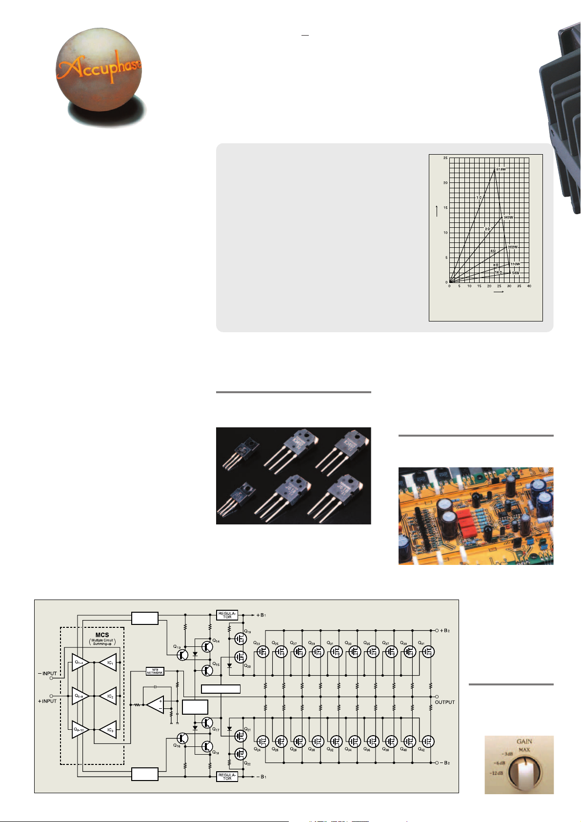
Note 2 The constant drive voltage principle
Even in the presence of a load with wildly fluctuating impedance,
the ideal power amplifier should deliver a constant voltage signal
to the load. Figure 2 shows the results of actual output voltage/
output current measurements at different load impedances for the
A-60. It can be clearly seen that output voltage is almost constant
at various loads, which means that current increases in a linear
fashion. Actual measurements of clipping power have yielded the
following figures, which impressively demonstrate the more than
ample performance of the A-60: 1 ohm: 513 watts, 2 ohms:
343 watts, 4 ohms: 202 watts, 8 ohms: 110 watts.
Power MOS-FET output stage with 10-parallel pushpull power units delivers 480 watts into 1 ohm, 240
watts into 2 ohms, 120 watts into 4 ohms, or 60
watts into 8 ohms with outstanding linearity
* 1-ohm loads to be driven with music signals only
The output stage (Figure 1) uses power MOS-FETs.
10 pairs of these devices are arranged in a parallel
Power MOS-FETs
push-pull configuration for each channel. The result
is stable operation with ideal power linearity even
down to ultra-low impedances. The maximum power
dissipation of one MOS-FET is 130 watts, but the
actual power load per pair is only 6 watts, so that
each device is driven only in its low-power range
Output current (A)
Output voltage (V)
* 1-ohm operation possible
Fig. 2 Output power vs. load impedance
(output voltage/output current)
where linearity is excellent.
A music signal consists of a continuous succession
of pulse waveforms. To prevent clipping on occasional
momentary high-level pulses, the maximum clipping
level of the A-60 is set to 100 watts per channel into
8 ohms.
MCS topology in input stage reduces residual noise
and drastically improves S/N ratio
The input stage which has an important role to play
features Accuphase's innovative MCS (Multiple Circuit
Summing) design. Three separate unit amplifiers for
the input signal are connected in parallel, which
with music signals only
minimizes noise and
distortion and greatly
improves other performance
parameters as well. This
manifests itself in further
improved sound quality.
BIAS
STABILIZER
CONSTANT
CURRENT
CIRCUIT
BIAS STABILIZER
Gain control also switches
NFB for reduced noise floor
The gain control of the A-60
has four positions: MAX,
–3 dB, –6 dB, –12 dB.
Reducing the gain also results
Fig. 1 Circuit diagram of amplifier section (one channel)
Page 3

in correspondingly lower noise,
which can be very beneficial when
driving high-efficiency speakers
where residual noise can be a problem.
Current feedback circuit topology
assures excellent phase characteristics
in high range
In the A-60, the signal current rather than the
more conventionally used voltage is used for feed-
Power amplifier assembly with 10parallel push-pull output devices
mounted to large heat sink, MCS
circuit, and current feedback
amplifier circuitry (one channel)
– Input
Buffer
+ Input
Buffer
Fig. 3 Principle of current feedback amplifier
Current
adder
I-V
converter
Trans-impedance
amplifier
Current NFB
network
Amplifier
Output
back. Since the impedance at the current feedback point (current adder in Figure 3) is very low,
there is almost no phase shift. Phase compensation therefore can be kept at a minimum. A minimal
amount of NFB results in maximum improvement of
circuit parameters. The result is excellent transient response
and superb
sonic transparency, coupled
(Large)
with utterly
natural energy
balance. Figure
4 shows frequency response for dif-
Gain
Fig. 4 Frequency response with current feedback
(Response remains uniform also when gain changes)
Frequency
(High)
ferent gain settings of the current feedback amplifier. The graphs demonstrate that response remains uniform over a
wide range.
Bridged operation mode creates true monophonic
amplifier with 960 watts into 2 ohms, 480 watts
into 4 ohms or 240 watts into 8 ohms
* 2-ohm loads to be driven with music signals only
Bridged connection turns the A-60 into a monophonic
amplifier with four times more power than during
stereo operation. The result is an extremely capable
performer with almost unlimited reserves.
Robust power supply with large "Super Ring"
toroidal transformer and 82,000 µF filtering
capacity
The power supply section is a critical aspect of
any power amplifier. The A-60 features a large
toroidal power transformer with a rating of about 1
kVA. The transformer is housed in a non-resonant
aluminum enclosure filled with
damping material
that has excellent
heat transfer characteristics. Toroidal transformers
which use heavygauge copper wiring on a ringshaped core have
important advantages for audio applications, such as
very low impedance, small size,
and high conversion efficiency.
Page 4

Power meters switchable for digital readout and bar graph indication
The power meters of the A-60 have a dual function. They can show a digital
readout of true output power (5 digits), or operate as a bar graph indicator with
25 LED points. The meter
selector has positions for
meter OFF, different watt
ranges, and bar graph
operation.
Power meter block diagram
Meter OFF
Meter range
Bar graph switching
Hold time
selection
nn
n Oversize speaker terminals compatible with Y lugs and banana
nn
plugs
nn
n Balanced connection eliminates induced noise
nn
nn
n Input type selector button (balanced/unbalanced) on front panel
nn
nn
n PCB copper foil and all major signal path components are gold-
nn
plated
nn
n Meter hold time can be switched to
nn
1 second or infinite
nn
n Selector allows switching to Dual Mono,
nn
Stereo, or Bridged operation
This indication is shown
for a few seconds after
power-on when bridged
mode is selected
Voltage
detector
Current
detector
Voltage
detector
Current
detector
n n
n Front panel
n n
n n
n Rear panel
n n
A
Hold time indicator
B
Left/right channel power meters
(digital readout/bar graph switchable)
C
Input type indicator
D
Meter switch
(OFF, range selection, bar graph)
E
Hold time selector (1 second/ )
F
Power switch
G
Input selector
H
Gain selector
(MAX,– 3 dB, – 6 dB,– 12 dB)
Remarks
★
This product is available in versions for 120/230 V AC. Make sure that the voltage
shown on the rear panel matches the AC line voltage in your area.
★
The shape of the AC inlet and plug of the supplied power cord, and the circuit
breaker current rating depend on the voltage rating and destination country.
18-bit
A/D converter
18-bit
A/D converter
18-bit
A/D converter
18-bit
A/D converter
DSP
Absolute value
conversion
Multiplication
Peak hold
I
Left/right channel speaker output terminals
J
Unbalanced inputs
K
Balanced inputs
a Ground
b Inverted (–)
c Non-inverted (+)
L
Mode selector
DUAL MONO NORMAL BRIDGE
M
AC circuit breaker
N
AC power connector
Microprocessor
★
★
★
★
Left-channel
5-digit display
Left-channel
bar graph
Right-channel
5-digit display
Right-channel
bar graph
n Supplied accessories: • AC power cord
Assembly with meter circuitry and protection circuitry
Unbalanced and balanced input connectors
Large speaker terminals
Gold-plated parts
GUARANTEED SPECIFICATIONS
[Guaranteed specifications are measured according to EIA standard RS-490.]
m Continuous Average Output Power (20 - 20,000 Hz)
Stereo operation 480 watts per channel into 1 ohm (❇)
(both channels driven) 240 watts per channel into 2 ohms
Monophonic operation 960 watts into 2 ohms (❇)
(bridged connection) 480 watts into 4 ohms
Note: Load ratings marked (❇) apply only to operation with music signals.
m Total Harmonic Distor tion Stereo operation (both channels driven)
m Intermodulation Distortion 0.003%
m Frequency Response At rated output: 20 - 20,000 Hz +0, –0.2 dB
mm
m Gain 28.0 dB (GAIN selector: MAX, stereo/monophonic operation)
mm
mm
m Gain Switching Max (28 dB), –3 dB (25 dB), –6 dB (22 dB), –12 dB (16 dB)
mm
mm
m Output Load Impedance Stereo operation: 2 to 16 ohms
mm
❇ With music signals only, 1-ohm loads are permissible for stereo operation and 2-ohm
loads for monophonic operation.
mm
m Damping Factor 100
mm
mm
m Input Sensitivity Stereo operation 0.87 V for rated output (6 0 W)
mm
(with 8 ohm load) 0.11 V for 1 watt output
mm
m Input Impedance 40 kilohms (balanced), 20 kilohms (unbalanced)
mm
mm
m Signal-to-Noise Ratio 112 dB at rated output, input shorted
mm
(A-weighted)
mm
m Output Level Meters
mm
(digital and bar graph)
✽ Display can be switched off. ✽ Same indication for left/right in monophonic mode
mm
m Power Requirements AC 120 V / 230 V, 50 / 60 Hz
mm
mm
m Power Consumption 300 watts idle
mm
mm
m Maximum dimensions Width 465 mm (18-5/16”)
mm
mm
m Mass 45.1 kg (99.4 lbs.) net
mm
120 watts per channel into 4 ohms
060 watts per channel into 8 ohms
240 watts into 8 ohms
0.07%, with 2-ohm load
0.05%, with 4 to 16-ohm load
Monophonic operation (bridged connection)
0.03%, with 4 to 16 ohms load
At 1 watt output: 0.5 - 160,000 Hz +0, –3.0 dB
Monophonic operation: 4 to 16 ohms
Monophonic operation 1.74 V for r ated output (240 W)
Digital meters: 5-digit indication, with range selection for 10W/100W/1000W
Bar graph meters: 25-point indication
Hold time: 1 second/ (switchable)
(Voltage as indicated on rear panel)
550 watts in accordance with IEC-65
Height 238 mm (9-3/8”)
Depth 545 mm (21-7/16”)
54.0 kg (119.0 lbs.) in shipping carton
0.11 V for 1 watt output
• Specifications and design subject to change without notice for improvements.
D0405Y PRINTED IN JAPAN 851-0137-00 (AD1)http://www.accuphase.com/
 Loading...