

Page 1
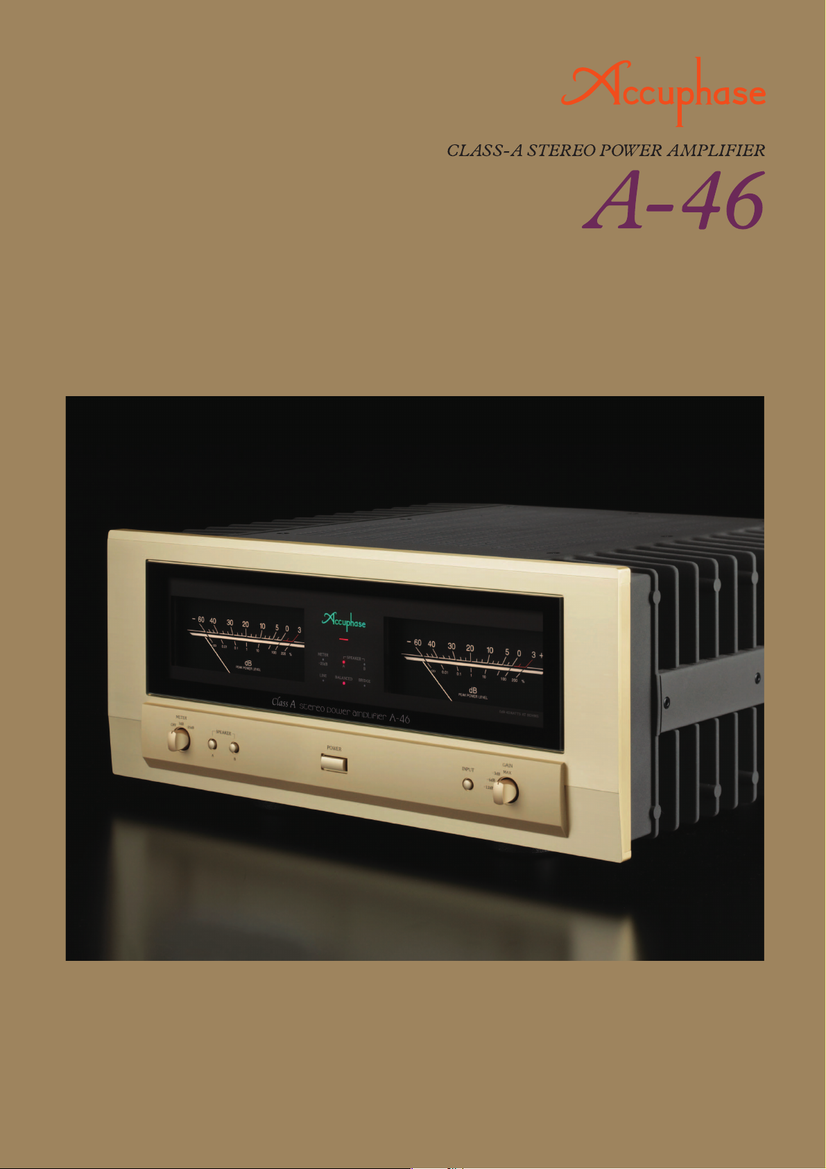
●Pure Class A operation delivers quality power: 45 watts x 2 into 8 ohms
●
Power MOS-FET output stage features 6-parallel push-pull configuration
●
Instrumentation amplifier principle ●Further improved MCS+ circuit
topology ●
sound ●
●
Current feedback combines stable operation with outstanding
Bridged mode allows upgrading to true monophonic amplifier
Large high-efficiency toroidal transformer ●4-step gain control
Page 2
Pure Class A power amplifier with power MOS-FET devices – Fully balanced signal paths
realized through instrumentation amplifier configuration. Further refined MCS+ topology
and current feedback result in superb sound quality and excellent ratings for S/N ratio,
THD, and other parameters. Strong power supply and power MOS-FET devices in
six-parallel push-pull configuration sustain an amazing 360 watts per channel into ultra-low
impedance 1-ohm loads (with music signals). 4-step gain control provides flexibility.
Pure Class A power amplifiers from Accuphase
have long been blending the purity of class A
operation with the superior performance of
power MOS-FETs. Acclaimed by audiophiles
the world over, these products reflect a level of
technical know-how that is second to none.
Each model in the A-65/A-45/A-35 lineup has
received high praise, both for sound quality and
performance. The A-46 is a minor-change
successor to the A-45, positioned as the
medium power level model of the series.
Naturally, the A-46 also demonstrates the same
unwavering dedication to sound quality and
outstanding design policy which are the
hallmark of Accuphase. This pure class A stereo
power amplifier with its distinctive external heat
sinks is built for the true enjoyment of music.
The A-46 uses latest instrumentation amplifier
topology throughout, which allows fully balanced
transmission in all signal handling stages. The
power amplifier section features further
improved MCS+ topology and the renowned
current feedback approach. This results in
electrical characteristics that surpass even the
demanding standards set by its predecessors.
Employing only highest grade materials and
strictly selected parts, the A-46 realizes very low
output impedance which ensures that constant
drive voltage is available for the speakers.
The output stage features power MOS-FETs
renowned for their excellent sound and superior
reliability. For each channel, six of these devices
are arranged in a parallel push-pull class A
arrangement. MOS-FETs have excellent frequency
response characteristics and high input impedance,
which reduces the load of the preceding (drive)
stage. Driving these devices in pure class A means
that constant power is always supplied, regardless
of the presence or absence of a musical signal.
This makes the amplifier completely immune to
external influences and ensures stable operation at
all times. The large heat sinks mounted on the
outside reliably prevent internal heat buildup,
allowing the amplifier to sustain output levels of as
much as 360 watts per channel into 1 ohm (with
music signals). If even higher power is required,
bridged mode turns the A-46 into a high-grade
monophonic power amplifier.
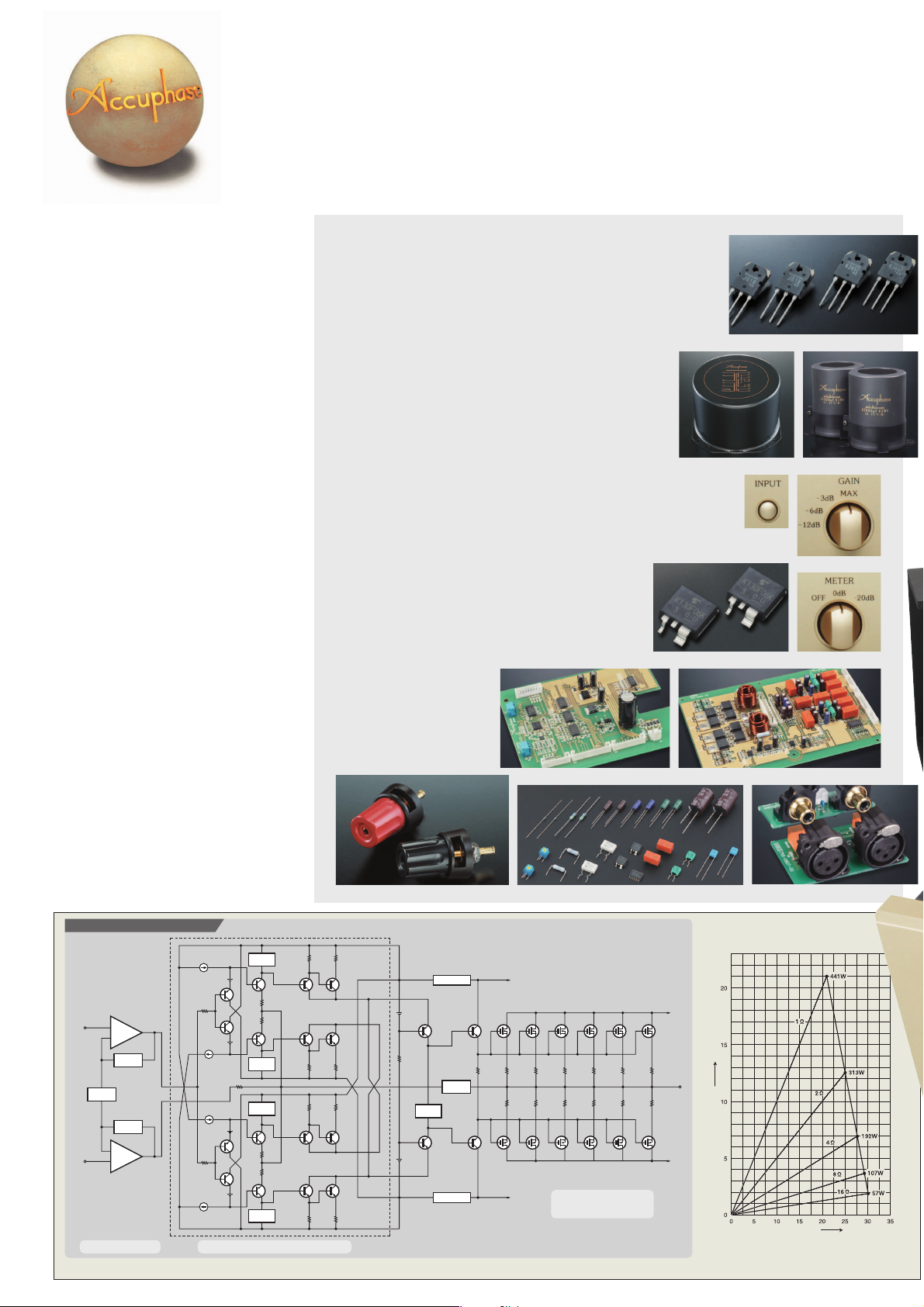
■ Power modules with 6-parallel push-pull arrangement of power
MOS-FETs deliver a guaranteed linear output of 360 watts per
channel into 1 ohm (music signals only), 180 watts into 2 ohms, 90
watts into 4 ohms, or 45 watts into 8 ohms.
■ Amply dimensioned power supply with high-efficiency toroidal
transformer and two large 47,000 μF filtering capacitors.
■ Bridged mode allows upgrading to monophonic amplifier
with 720 watts into 2 ohms (music signals only), 360 watts
into 4 ohms, or 180 watts into 8 ohms.
■ Revised NFB design minimizes output impedance and
increases damping factor, resulting in further improved
sound quality.
■ Fully balanced input stage shuts out external noise
interference.
■ Mode selector for easy switching between dual
Toroidal power transformer
mono/stereo/bridged operation
■ Front panel input type selector (line/balanced).
■ 4-step gain control (MAX, -3 dB, -6 dB, -12 dB) minimizes
residual noise.
Large analog power meters with operation/illumination
■
and sensitivity selector.
■ Speaker protection uses semiconductor (MOS-FET)
switch. Elimination of mechanical switches assures
long-term reliability and improved signal purity,
resulting in further improved sound quality.
■ PCB copper foil and all
major signal path
components are goldplated.
■ Two sets of speaker
outputs, with large
terminals that accept also
Y lugs.
Large speaker terminals
Meter circuitry assembly
Parts selected for sound quality and reliability
Power MOS-FETs
Filtering capacitors
Input selector
Gain selector
Meter selectorMOS-FET switches
Protection circuitry
Line/balanced input connectors
Instrumentation amplifier
+
INPUT
+
–
NFB
NETWORK
GAIN CONTROL
CIRCUIT
NFB
NETWORK
–
+
– INPUT
Gain control
Bias stabilizer
circuit
Q
17
Bias stabilizer
circuit
Q
18
REGULATOR
NETWORK
REGULATOR
Q
1
Q
Q
9
Q11Q
Q10Q
Q12Q
Q
13
15
14
16
5
Q
7
Q
3
Bias stabilizer
circuit
Bias stabilizer
circuit
Q
2
Q
6
Q
8
Q
4
Bias stabilizer
circuit
MCS+ (Multiple Circuit Summing)
Figure 1 Circuit diagram of amplifier section (one channel)
★1-ohm operation possible
with music signals only
+ B1
Q
Q
19
NFB
Q
20
Q23Q25Q27Q
21
Q
Q24Q26Q28Q
22
–
B 1
29
30
Power MOS-FETs
6-parallel push-pull
+ B2
Q
31
OUTPUT
–
B 2
Output current (A)
Output voltage (V)
Figure 2 Load impedance vs.
output power
(output voltage/output current)
Q
32
Page 3

Instrumentation amplifier and further refined MCS+ topology
Instrumentation amp configuration allows
fully balanced signal paths
The advanced instrumentation amplifier
principle used in the A-46 ensures that all
signal paths from the inputs to the power amp
stage are fully balanced. This results in
excellent CMRR (common mode rejection
Signal input stage
NFB
NETWORK
+
−
NFB
NETWORK
NFB
NETWORK
−
+
+
INPUT
−
INPUT
Instrumentation amplifier configuration
Power amplifier stage
+
−
OUTPUT
ratio) and minimal distortion. Another
significant advantage is that external noise
and other external influences are virtually shut
out. The result is a drastic improvement in
operation stability and reliability.
Further refined MCS+ topology for even
lower noise
Accuphase's original MCS (Multiple Circuit
Summing) configuration uses a number of
identical circuits connected in parallel to achieve
superior performance characteristics. MCS+ is
a further refined version of this approach. By
extending parallel operation to the class-A drive
stage of the current/voltage converter, the noise
floor has been lowered further.
■
Power amplifier assembly with six parallel push-pull
power MOS-FET pairs per channel mounted directly to
large heat sink, MCS+ circuitry, and current feedback
amplifier.
Current feedback principle assures excellent
phase characteristics in high range
As shown in the illustration, the A-46 uses the
output signal current rather than voltage for
feedback. Since the impedance at the current
feedback point is very low, there is almost no
phase shift. A minimal amount of NFB
therefore results in maximum improvement of
circuit parameters.
(+) input buffer
(-) input buffer
Current adder
/V
converter
Trans-impedance amplifier
Current NFB
network
Amplifier
Principle of current feedback amplifier
Output
Phase selector for balanced input
●
In the factory default
condition, the switch is
set to the left side ("pin
e +"), as shown in the
illustration.
●
If the balanced output
of the connected
preamplifier has a "pin
+" arrangement, the
w
switch should be set to
the right side.
Page 4

■
Using two A-46 units, bi-amping or bridged connection can be realized, for even higher performance.
■In this case, only the LEFT input (BALANCED or LINE) of each unit is used.
Connection example for bi-amping setup Connection example for bridged setup
+−+
−
Right loudspeaker
+○−
○+○−○
LOW
HIGH
−○+
○
Left loudspeaker Right loudspeakerLeft loudspeaker
In a bi-amped setup, the speaker units for the
LOW frequency range and HIGH frequency
range are driven by separate amplifiers, for
enhanced sound quality.
*A speaker with a built-in crossover network
HIGH
and separate inputs for LOW and HIGH range
is required.
R
LRL
+−+
−
LOW
+○−○+○−
○
In bridged mode, the A-46 becomes a
monophonic amplifier with even higher power
output.
−
* The speaker terminals of the A-46 are not used.
RIGHT
+ RIGHT
LEFT+
−○+
○
+
LEFT+
A-46
for left
channel
To left channel input To left channel input
L
Preamplifier Preamplifier
■ Front panel
er tyu
■ Rear panel
!0 !3
o!1
q Right/left-channel output power meters
(dB and % scale)
w Function indicators
METER −20 dB SPEAKER A, B
LINE BALANCED BRIDGE
e
Meter operation/illumination and sensitivity selector
OFF, 0 dB, −20 dB
r Speaker selector buttons
A: ON/OFF, B: ON/OFF
t Power switch
y Input selector button
LINE, BALANCED
R
Mode selector of both A-46 units
set to DUAL MONO position
q w
!2i
★
u Gain selector
MAX, −3 dB, −6 dB, −12 dB
i Line inputs
o Balanced inputs
Pin (2) − Pin (3) +
(Can be switched with phase selector switch
!0 Mode selector
DUAL MONO, NORMAL, BRIDGE
!1 Balanced input phase selector switch
!2 Right/left-channel speaker output terminals
A/B, 2 sets
!3 AC power supply connector
★
A-46
for right
channel
A-46
for left
channel
To left channel input To left channel input
L
R
“BRIDGE” LED on front
panel of both A-46 units lit
A-46 Guaranteed Specifications
[Guaranteed specifications are measured according to EIA standard RS-490.]
● Continuous Average Output Power (20 - 20,000 Hz)
Stereo operation 360 watts per channel into 1 ohm (*)
(both channels driven) 180 watts per channel into 2 ohms
90 watts per channel into 4 ohms
45 watts per channel into 8 ohms
Monophonic operation 720 watts into 2 ohms (*)
(bridged connection) 360 watts into 4 ohms
180 watts into 8 ohms
Total Harmonic Distortion
●
Stereo operation (both channels driven)
0.05% with 2 ohms load
Monophonic operation (bridged connection)
●
Intermodulation Distortion
● Frequency Response At rated output: 20 - 20,000 Hz +0, −0.2 dB
At 1 watt output: 0.5 - 160,000 Hz +0, −3.0 dB
● Gain 28.0 dB (with GAIN selector at MAX)
(in stereo and bridged operation)
● Gain Selection MAX, −3 dB, −6 dB, −12 dB
● Output Load impedance Stereo operation: 2 to 16 ohms
Bridged operation: 4 to 16 ohms
● Damping Factor 500
● Input Sensitivity (with 8-ohm load, GAIN selector in MAX position)
Stereo operation: 0.76 V for rated output
0.11 V for 1 watt output
Bridged operation: 1.51 V for rated output
0.11 V for 1 watt output
● Input Impedance Line: 20 kilohms Balanced: 40 kilohms
● Signal-to-Noise Ratio
(A-weighted, input shorted)
120 dB (GAIN selector in −12 dB position)
At rated output
● Speaker leakage level
at OFF setting −55 dB or less (10 kHz, 8 ohm load)
● Output Level Meters −60 dB to +3 dB (indication in dB and %)
● Power Requirements AC 120 V/220 V/230 V, 50/60 Hz
(Voltage as indicated on rear panel)
!1
)
● Power Consumption 200 watts idle
410 watts in accordance with IEC 60065
● Maximum Dimensions Width 465 mm (18-5/16")
Height 211 mm (8-5/16")
Depth 464 mm (18-1/4")
● Mass 31.9 kg (70.3 lbs)net
39.0 kg (86.0 lbs) in shipping carton
Note: Load ratings marked (*) apply only to operation with music signals.
0.03% with 4 to 16 ohms load
0.05% with 4 to 16 ohms load
0.01%
With music signals only, 1-ohm loads are permissible for stereo
operation and 2-ohm loads for bridged operation.
115 dB (GAIN selector in MAX position)
Logarithmic scale, with illumination off switch and
sensitivity selector (−20 dB)
A-46
for right
channel
Mode selector of both A-46
units set to BRIDGE position
Remarks
★This product is available in versions for 120/220/230 V AC. Make sure that the voltage shown on the rear panel matches the AC line voltage in your area.
★The shape of the AC inlet and plug of the supplied power cord depends on the voltage rating and destination country.
■
Supplied accessory
●
A
C power cord
●
Specifications and design subject to change without notice for improvements.
E1105Y PRINTED IN JAPAN 851-0205-00(B1)
 Loading...