

Page 1
● Pure Class A operation delivers quality power: 30 watts x 2 into 8 ohms ● Power MOS-
FET output stage features 3-parallel push-pull configuration ● Instrumentation amplifier principle
used in input stage ● Amplification stage implements further evolved MCS+ topology ● Current
feedback principle combines stable operation with outstanding sound quality ● Bridged
connection mode allows upgrading to monophonic amplifier ● Strong power supply with
massive high-efficiency transformer and large filtering capacitors ● 4-stage gain control
Page 2
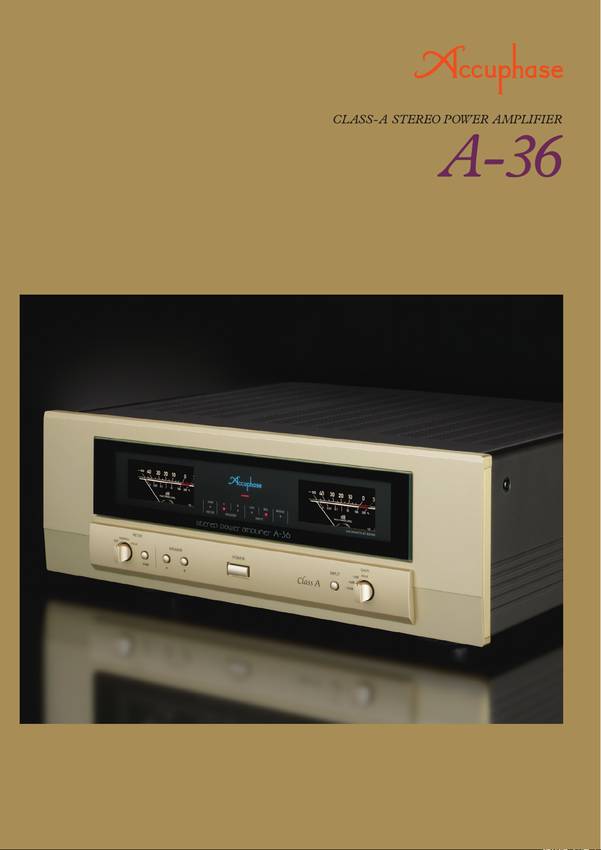
Redefining Essential Excellence Impressive Baseline Pure Class A Stereo
Power Amplifier. Input stage features fully balanced signal paths realized with ultra
low noise instrumentation amplifier topology. MCS+ design and current feedback
in amplification circuitry deliver outstanding S/N ratio and other performance
parameters for improved sound quality. Robust power supply and power
MOS-FET devices in triple-parallel push-pull configuration sustain power output of
150 watts per channel (music signals) down to impedances as low as 1 ohm. Output
stage with further lowered impedance realizes a damping factor of 400.
Pure Class A amplifiers from Accuphase have a long
and distinguished tradition and have attained widely
acclaimed levels of performance combined with
reliability and impeccable sound quality. Audiophiles
the world over continue to hold them in high esteem.
The Pure Class A Monophonic Power Amplifier
A-200 introduced on the occasion of the company's
40th anniversary, and the high-end Pure Class A
Stereo Power Amplifier A-70 opened up new realms
of sonic excellence and have become legendary as
reference audio devices. The new A-36 inherits
many of the outstanding design technology features
developed for the higher-end models. It redefines the
baseline for pure class A power amplifiers and represents the same unwavering attention to detail and
dedication to sound quality for which Accuphase is
justly famous.
Latest instrumentation amplifier topology allows the
realization of fully balanced signal paths, while the
MCS+ circuitry combined with current feedback
topology and carefully selected high-grade materials
assure further enhanced performance and sound
quality. In the output stage, power MOS-FETs
renowned for their excellent frequency response,
sonic performance, and superior reliability are used
in a triple parallel configuration and driven in pure
class A. This is sustained by the strong power supply
featuring a massive transformer and two large
47,000 μF filtering capacitors. Output power in each
channel is rated for an impressive 150 watts into
1 ohm, 120 watts into 2 ohms, 60 watts into 4 ohms,
and 30 watts into 8 ohms. Even speakers with ultralow impedance or drastic fluctuations in impedance
curve can be driven reliably by this impressive amplifier. In the output circuitry, MOS-FET switches are
used in place of relays, to eliminate mechanical
contacts and improve long-term reliability. Top-grade
materials, sophisticated circuit pattern technology,
and various other measures result in low impedance
and allow the realization of a damping factor of 400,
which represents a two-fold improvement over the
A-35. The well-proven analog power meters are
equipped with a sensitivity selector for easy observation of low power levels, and a peak hold function
has been newly added.
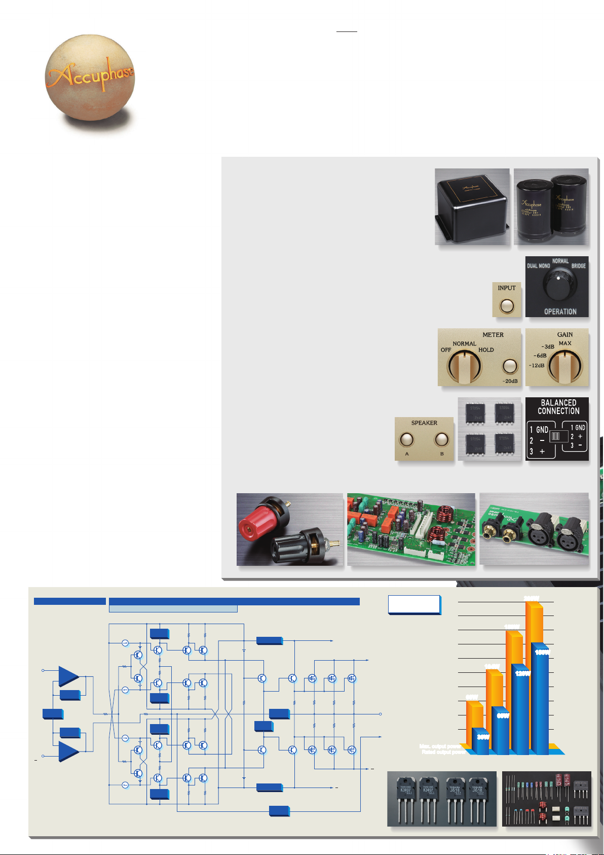
■3-parallel push-pull arrangement of power
MOS-FETs delivers 150 watts (music signal)
into 1 ohm, 120 watts into 2 ohms, 60 watts
into 4 ohms, or 30 watts into 8 ohms.
■ Strong power supply with large high-efficiency
transformer and two 47,000 μF filtering capacitors.
■ Instrumentation amplifier principle for power
amplifier input stage allows fully balanced
signal transmission. MCS+ topology further improves S/N ratio.
■ Bridging allows upgrade to monophonic amplifier with even
higher power, delivering 300 watts into 2 ohms (music signal),
240 watts into 4 ohms, or 120 watts into 8 ohms.
■ Operation mode switch supports dual mono operation and
allows bi-amping connection.
■ Damping factor doubled to 400 contributes to enhanced
sonic definition.
■ Analog power meters.
Meter operation/light on/off switch, peak hold/normal
operation selector, sensitivity selector (0 dB, -20 dB).
■ 4-stage gain selector (MAX, -3 dB, -6 dB, -12 dB)
also minimizes residual noise.
■Semiconductor (MOS-FET) switches used for
protection circuitry.
Meter controls
Prevent contact problems and ensure long-term reliability.
Eliminating mechanical contacts from
signal path also further enhances sound
quality.
■ Balanced input phase selector switch.
If balanced input of preamplifier uses
pin 2 positive configuration, this switch
can be used for proper matching.
Speaker selector buttons
MOS-FET switches Phase selector
■ Two sets of large speaker terminals (A / B) also accept Y lugs.
Large speaker terminals
Protection and meter circuit assembly
Filtering capacitorsPower transformer
Input selector button
Line and balanced input connectors
Operation mode selector
Gain control selector
+
INPUT
INPUT
GAIN CONTROL
CIRCUIT
Signal input stage
+
−
FEEDBACK
NETWORK
FEEDBACK
NETWORK
−
+
MCS+ (Multiple Circuit Summing)
BIAS
STABILIZER
CIRCUIT
Q
1
Q
3
Q
2
Q
4
Q
5
Q
7
BIAS
STABILIZER
CIRCUIT
BIAS
STABILIZER
CIRCUIT
Q
6
Q
8
BIAS
STABILIZER
CIRCUIT
Q
9
Q11Q
Q10Q
Q12Q
Fig. 1 Circuit diagram of amplifier section (one channel)
Power amplification stage
Q
13
15
14
16
REGULATOR
Q
17
BIAS
STABILIZER
CIRCUIT
Q
18
REGULATOR
NFB
NETWORK
NFB
NETWORK
Q
19
Q
20
+B1
Q21Q23Q
Q22Q
24
B1
200W
Output power
characteristics
+B2
25
OUTPUT
SPEAKER
TERMINAL
Q
26
B2
200
180
160
140
120
100
Output power (W)
80
60
40
20
Max. output powerMax. output power
Rated output power
Rated output power
Power MOS-FETs
104W
104W
60W
60W
30W
30W
8Ω 4Ω 2Ω 1Ω
200W
159W
159W
150W
150W
120W
120W
60W60W
Impedance (Ohms)
Parts selected for high sound quality and reliability
Page 3

Instrumentation amplifier configuration and further refined MCS+ topology
Amplification stage features instrumentation
amplifier topology for fully balanced signal paths
The instrumentation amplifier principle ensures
that all signal paths from the inputs to the
power amp stage are fully balanced. This not
only results in excellent CMRR (Common Mode
Rejection Ratio) and minimal distortion, it also
makes the amplifier highly resistant against
external noise and other external influences.
The result is a drastic improvement in operation
stability and reliability.
Power amplifier stageSignal input stage
INPUT
GAIN CONTROL
CIRCUIT
+
–
FEEDBACK
NETWORK
FEEDBACK
NETWORK
–
+
+
OUTPUT
–
+
‒ INPUT
Instrumentation amplifier principle
Further refined MCS+ topology for even
lower noise
MCS+ is a further refined version of this approach.
By extending parallel operation to the class-A
drive stage of the current/voltage converter, the
noise floor has been lowered further.
Current feedback principle assures excellent
phase characteristics in high range
As shown in the illustration, the A-36 uses the output
signal current rather than voltage for feedback.
Since the impedance at the current feedback point
is very low, there is almost no phase shift. A minimal
amount of NFB therefore results in maximum
improvement of circuit parameters.
−INPUT
+INPUT
TRANS-IMPEDANCE AMPLIFIER
BUFFER
BUFFER
/V
CONVERTER
CURRENT ADDER
CURRENT NFB
NETWORK
Principle of current feedback
amplifier
AMPLIFIER
OUTPUT
Power amplifier assembly
Power amplifier assembly with
3-parallel push-pull power
MOS-FET arrangement mounted
directly to large heat sink, also
comprising MCS+ circuitry and
current feedback amplifier.
Accuphase’s original MCS (Multiple Circuit
Summing) principle uses a number of identical
circuits connected in parallel to achieve
superior performance characteristics.
Page 4
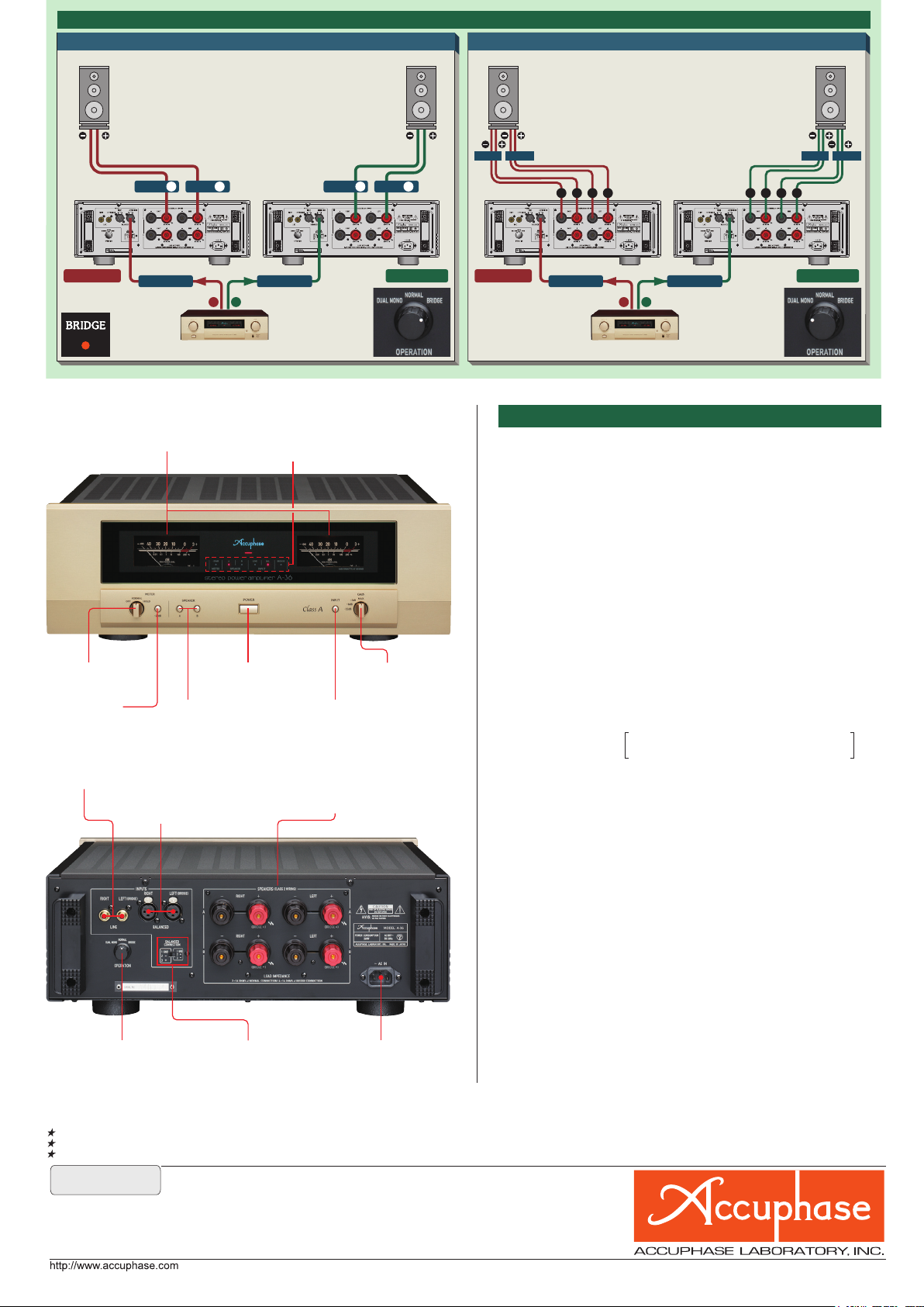
■ Using two A-36 units, upgrade to bridged operation or bi-amping is possible. ■ Use the LEFT (BALANCED or LINE) input connectors for both units.
Connection example for bridged setup
Left loudspeaker Right loudspeaker Left loudspeaker Right loudspeaker
When the operation mode selector is set
to bridged mode, the A-36 becomes a
monophonic amplifier with even higher
power output.
−
*The ● speaker terminals of the A-36 are not used.
LOW
Connection example for bi-amping setup
In a bi-amped setup, the speaker units for
the LOW frequency range and HIGH
frequency range are driven by separate
amplifiers, for optimum sound quality.
*The speakers must have a built-in crossover network
HIGH
and separate inputs for LOW and HIGH range.
LOW
HIGH
RIGHT+
A-36 for left channel A-36 for right channel A-36 for left channel A-36 for right channel
BRIDGE LED on
front panel lit on
both A-36 units
LEFT+
To left channel inputTo left channel input
L
R
Preamplifier Preamplifier
RIGHT+
Operation mode
selector set to
BRIDGE on both
A-36 units
■ Front Panel
q Right/left-channel output power meters
(dB and percent indication, switchable)
e
Meter selector
OFF / NORMAL /
HOLD (
)
r
∞
-20 dB button t Speaker selector buttons
y Power switch
A: ON/OFF B: ON/OFF
wFunction indicator LEDs
-20 dB METER / SPEAKER A,B / LINE /
BALANCED / BRIDGE
u Input selector button
LINE / BALANCED
■ Rear Panel
o Line inputs
!2 Operation mode
selector
DUAL MONO /
NORMAL / BRIDGE
!0
Balanced inputs
② Inverted ( – ) ③ Non-inverted (+)
(Can be changed with phase selector
switch !3)
!3 Balanced input phase selector switch
!1 Right/left-channel speaker
output terminals
A / B, two sets
LEFT+
i Gain selector
MAX / -3 dB /
-6 dB / -12 dB
!4 AC power supply
connector
★
+−+
−
To left channel inputTo left channel input
L
R
+−+
Operation mode
selector set to
DUAL MONO on
both A-36 units
−
A-36 GUARANTEED SPECIFICATIONS
[Guaranteed specifications measured according to EIA standard RS-490]
●Continuous Average Output Power (20–20,000 Hz)
Stereo operation 150 watts per channel into 1 ohm (*)
(both channels driven) 120 watts per channel into 2 ohms
60 watts per channel into 4 ohms
30 watts per channel into 8 ohms
Monophonic operation 300 watts into 2 ohms (
(bridged connection) 240 watts into 4 ohms
120 watts into 8 ohms
●
Total Harmonic Stereo operation (both channels driven)
Distortion 0.05% with 2 ohm load
0.03% with 4 to 16 ohm load
0.05% with 4 to 16 ohm load
Intermodulation Distortion
●
Frequency Response At rated output: 20 – 20,000 Hz +0, -0.2 dB
●
At 1 watt output: 0.5 – 160,000 Hz +0, -3.0 dB
Gain 28.0 dB (with GAIN selector at MAX)
●
(Stereo and monophonic operation)
Gain Selection MAX, -3 dB, -6 dB, -12 dB
●
Output Load impedance
●
Stereo operation: 2 to 16 ohms
Monophonic operation: 4 to 16 ohms
With music signals only, 1-ohm loads are
●
Damping Factor 400
●
Input Sensitivity (with 8-ohm load, GAIN selector in MAX position)
Stereo operation: 0.62 V for rated continuous average output (30 W)
0.11 V for 1 watt output
Monophonic operation: 1.23 V for rated continuous average output (120 W)
0.11 V for 1 watt output
●
Input Impedance
●Signal-to-Noise Ratio (A-weighted, input shorted)
112 dB (GAIN selector at MAX)
120 dB (GAIN selector at -12 dB)
At rated continuous average output
●
Output Level Meters -40 dB to +3 dB (indication in dB and %)
Logarithmic scale
Operation selector: OFF / NORMAL / HOLD (
Meter sensitivity selector (-20 dB)
*Monophonic operation: same value displayed for
left/right
●
Power Requirements AC 120 V/230 V, 50/60 Hz
(Voltage as indicated on rear panel)
●
Power Consumption 155 watts idle
270 watts in accordance with IEC 60065
●
Maximum Dimensions Width 465 mm (18.31")
Height 171 mm (6.73")
Depth 425 mm (16.73")
●
Mass 22.8 kg (50.27 lbs) net
29.0 kg (63.93 lbs) in shipping carton
Monophonic operation (bridged connection)
0.01%
permissible for stereo operation and 2-ohm loads
for monophonic operation.
Balanced: 40 kilohms Line: 20 kilohms
Note: Load ratings marked (*) apply only to
operation with music signals.
*)
∞
)
Remarks
This produc t is available in vers ions for 120/2 20/23 0 V AC. Make sure that the voltage shown on the rear panel matches the AC line voltag e in your area.
23 0 V version has an Eco M ode that switches power off af ter 120 minutes of inac tivity.
The shape of the AC inl et and plug of the supp lied power cor d depends on the vol tage rating and destinatio n country.
■
Supplied accessory:
●
AC power cord
●
The specifications and appearance of this product are subject to change without notice.
F1405Y PRINTED IN JAPAN 850-2187-00(B1)
 Loading...