

Page 1
m Pure Class-A operation delivers quality power: 20 watts × 2 into 8
ohms m Power MOS-FET output stage features 3-parallel push-pull
configuration and delivers linear power even into extremely lowimpedance loads m Current feedback design combines superb sound
quality with totally stable operation m Bridged mode allows use as a
monaural amplifier m Balanced inputs m Heavy-duty speaker terminals
Page 2
Pure Class-A goes straight for the heart of the music. The output stage uses
Current NFB
network
I/V
converter
Trans-impedance amplifier
(+) input
(–) input
Buffer
Buffer
Current
adder
Amplifier
Output
power MOS-FET devices arranged in a triple parallel configuration f or each
channel. Ultra-linear power progression reaches down to v ery low impedance
loads: 80 watts × 2 into 2 ohms. Current feedback topology assures stability
and creates an utterly convincing sound stage. Gain control makes the
amplifier perfectly suited also for use as midrang e/high-range amplifier in a
multi-amplifier system.
Accuphase power amplifiers are designed to
realize two major goals: very low output impedance
(Note 1), and constant drive voltage (Note 2). As a
result, Accuphase amplifiers are capable of driving
any kind of speaker load with optimum results,
which is one of the reasons for the high praise that
these products invariably receive. The low
impedance not only ensures accurate speaker
drive but also absorbs the counterelectromotive
force generated by the voice coil, thereby
eliminating a major source of intermodulation
distortion. The overall result is a significant
improvement in sound quality.
The A-20V is a pure class-A amplifier which fully
implements these advanced circuit design
principles. Another adv antage is the use of po wer
MOS-FET devices for further enhanced sonic
definition. In a pure class-A amplifier, the power
supply delivers a constant amount of power
regardless of the presence or absence of a music
signal. This means that the amplifier remains
unaffected by fluctuations in voltage and other
external influences. As a consequence of this
design, the output stage produces considerable
amounts of thermal energy, but in the A-20V this
is dissipated by extra-large heat sinks, to eliminate
the possibility of problems caused by internal heat
build-up.
The power MOS-FETs used in the output stage are
renowned for their superior sound and high reliability .
Because they exhibit negative thermal
characteristics, there is no danger of thermal
"runaway" as exists with bipolar transistors. Three
pairs of these devices are arranged in a parallel
push-pull configuration for each channel. The result
is stable operation with ideal power linearity even
down to ultra-low impedances.
The current feedback principle developed by
Accuphase requires only minimal amounts of
negative feedback to ensure outstanding phase
characteristics in the upper frequency range. This
approach combines operation stability with excellent
frequency response. A gain control is provided which
operates by modifying the NFB amount. This is
useful for example in m ulti-amp systems where even
minimal amounts of noise in the medium and high
frequency bands could be a problem.
Note 1 Low amplifier output impedance
The load of a power amplifier, namely the
loudspeaker, generates a counterelectromotive force that can flow back into the
amplifier via the NF loop. This phenomenon is
influenced by fluctuations in speaker
impedance, and interferes with the drive
performance of the amplifier. The output
impedance of a power amplifier should
therefore be made as low as possible by using
output devices with high current capability.
Note 2 Constant drive voltage principle
Even in the presence of a load with wildly
fluctuating impedance, the ideal power
amplifier should deliver a constant voltage
signal to the load. When the supplied voltage
remains constant for any impedance, output
power will be inversely proportional to the
impedance of the load. A conventional
amplifier can easily be made to operate in this
way down to a load impedance of about 4
ohms. However, at 2 ohms and below much
more substantial output reserves will be
needed, which can only be sustained by an
extremely well designed and capable output
stage and a highly robust and powerful power
supply section. To build such an amplifier is a
task that requires not only considerable
experience and resources, but also a thorough
reappraisal of basic tenets.
Power MOS-FET output stage with two units in
3-parallel push-pull configuration delivers 80
watts into 2 ohms, 40 watts into 4 ohms, or 20
watts into 8 ohms with outstanding linearity
The output stage (Figure 1) uses power MOS-FETs
with negative thermal characteristics. Three pairs
of these devices are arranged in a parallel pushpull configuration for each channel. The result is
stable operation with ideal power linearity even
down to ultra-low impedances. The parallel
connection cancels out impedance differences of
individual devices, thereby minimizing residual
noise. It also allows using the MOS-FETs in their
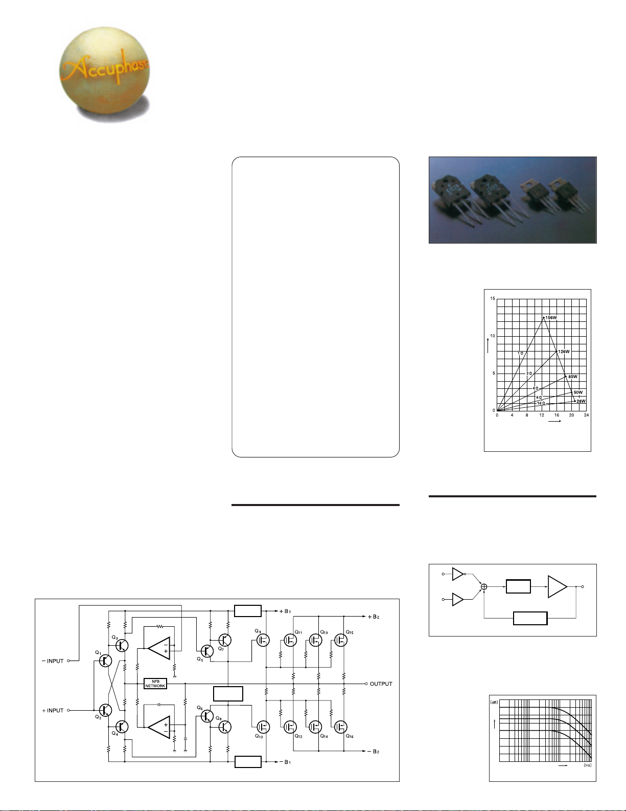
Power MOS-FETs
most linear low-power range, which further
contributes to sound quality.
Figure 2 shows the output voltage/current characteristics at various load impedances. Output voltage is almost
constant at
various loads,
meaning that
current increases linearly. Actual
measurements of clipping power
have yielded
the following
Output current (A)
figures, which
impressively
demonstrate
the more than
ample performance of the
Output voltage (V)
* 1-ohm operation possible with music signals only
Figure 2 Load impedance vs. output power
(output voltage/output current)
A-20V: 1 ohm: 156 watts, 2 ohms: 126 watts, 4
ohms: 85 watts, 8 ohms: 50 watts.
Current feedback topology prevents phase shifts
The amplifying circuits in the A-20V use the current feedback principle for negative feedback. At
the input point of the feedback loop, the impedance is kept low and current detection is perf ormed.
A trans-impedance amplifier then converts the
current into a voltage to be used as the feedback
STABILIZER
CIRCUIT
Figure 1 Circuit diagram of amplifier section
BIAS
REGULATOR
REGULATOR
Figure 3 Principle of current feedback amplifier
signal. Since the impedance at the current feedback point (current adder in Figure 3) is very low,
there is almost no phase shift. Phase compensation therefore can be kept at a minimum. A minimal amount of NFB results in maximum improvement of circuit
parameters. The
result is excellent transient response and superb sonic trans-
Gain (High)
parency,
coupled with utterly natural energy balance.
Figure 4 Frequency response with current feedback
(response remains uniform also when gain changes)
Frequency (High)
Page 3

Figure 4
shows frequency
response for different
gain settings of the current
feedback amplifier. The graphs
demonstrate that response remains uniform over a wide range.
NFB switching type gain control
The current feedback principle, which ensures low
phase shift and high stability, allowed the designers to implement a gain control (–3 dB, –6 dB, –9
dB, –12 dB) which operates by altering the NFB
amount. Consequently, when gain is lowered the
noise floor also becomes
lower, a desirable characteristic especially when
driving highly efficient
speakers. It also is advantageous when using
the A-20V as the
midrange/high-range unit
in a multi-amplified system where separate amplifiers drive the individual
speaker units.
Robust power supply with large power
transformer and high filtering capacity
In any amplifier, the power supply pla ys a vital role
since it acts as the original source for the output
delivered to the
speaker. The A-20V, in
spite of its conservative 20 W/8 ohms x 2
rating, employs a large
400 VA power transformer housed in an
enclosure filled with vibration-damping material. T wo electrolytic capacitors, specially selected for their sonic
properties and each
rated for 47,000 µF,
provide ample filtering
capacity for the rectified current. The capacitors feature an
elastic soft coating
which helps to make
them impervious to the detrimental influence of vibrations.
Bridged operation mode creates a
true monophonic amplifier with 160 watts
into 4 ohms or 80 watts into 8 ohms
Bridged mode means that the two channels of an
amplifier are driven with the same signal voltage
but with opposite phase, and their output is
combined. The A-20V provides a switch
arrangement for bridged operation, which turns the
unit into a high-grade monaural amplifier capable
of delivering a full 160 watts into 4 ohms or 80
watts into 8 ohms.
Balanced connection reliably blocks induced noise
Balanced signal transmission means that the
output stage of a component supplies two signal
lines which have identical voltage but opposite
phase. Since an y noise interference that has arisen
during transmission will be present in both lines
with identical phase, such noise can be canceled
out, leaving only the pure original signal. Even with
long cable runs, the balanced connection principle
keeps the signal transf er completely free from any
kind of interference.
Large analog power meters
The large power meters hav e a peak hold
function which lets the user easily monitor
the output level of the rapidly fluctuating
music signal. Thanks to logarithmic
compression, the meters cover a wide
dynamic range. A switch for meter
operation and illumination control is also
provided.
n Power amplifier assembly
with 3 parallel push-pull
MOS-FETs (total 6 devices for left and right
channel) and current feedback amplifier circuitry
mounted directly to mas-
sive aluminum diecast
heat sinks
Page 4

Major signal paths gold-plated
High-purity copper is commonly used in audio
components for signal path lines. The A-20V goes
one step further by providing gold-plating for
printed circuit board traces as well as for the input
jacks and speaker terminals. This approach results
in a distinct sonic improvement.
Extra-large speaker terminals
The oversize speaker terminals accommodate even
very heavy-gauge
speaker cable. The
terminals are made
of extruded highpurity brass and
are gold-plated for
utmost reliability
and minimum contact resistance.
Molded caps are
provided to assure
proper insulation.
Easy switching between dual mono operation
and bridged connection
mono position is useful
for example to drive a
center woofer in mono,
or to obtain the same
signal from both speaker
outputs for driving a biamped speaker setup
with separate amplifiers for the low and high frequency range.
Unbalanced connectors and balanced inputs
n FRONT PANEL
A
CDE
n REAR PANEL
F
G
J9
A Left-channel power meter (dB scale)
B Right-channel power meter (dB scale)
C Power METER OFF switch and range
selector
OFF NORMAL –20 dB
D POWER switch
E GAIN selector
MAX –3 dB –6 dB –9 dB –12 dB
F Unbalanced inputs
A mode selector makes it simple to switch between
dual mono, stereo, or bridged operation. The dual
B
H
H
K
G Balanced inputs
a GND b Inverted (–)
c Non-inverted (+)
H Left/right channel speaker output terminals
I Mode selector
DUAL MONO NORMAL BRIDGE
J Input selector
UNBALANCED BALANCED
K
AC input connector (for supplied po wer cord)
Assembly with protection circuitry, etc.
A-20V Guaranteed Specifications
[Guaranteed specifications are measured according to the EIAJ standard RS-490]
m Continuous Average Output Power (20 - 20,000 Hz)
Stereo operation
(both channels driven)
Monophonic operation
(bridged connection)
m Total Harmonic Distortion
Stereo operation (both channels driven) 0.05%, with 2-ohm load
Monophonic operation 0.02%, with 4 to 16 ohms load
(bridged connection)
m Intermodulation Distortion 0.003%
m Frequency Response At rated output : 20 - 20,000 Hz +0, –0.2 dB
m Gain (GAIN selector in MAX position) 28.0 dB (in stereo and monophonic operation)
m Output Load Impedance Stereo operation : 2 to 16 ohms
m Damping Factor Stereo operation : 120
m Input Sensitivity (with 8-ohm load)
Stereo operation 0.50 V for rated output
Monophonic operation 1.00 V for rated output
m Input Impedance Balanced : 40 kilohms
m Signal-to-Noise Ratio (A-weighted) 110 dB with input shorted, at rated output
m Output Level Meters
m Power Requirements 120V/230V (Voltage as indicated on rear panel)
m Power Consumption 160 watts idle
m Maximum Dimensions Width 475 mm (18-11/16")
m Weight 22.6. kg (49.8 lbs) net
H
180watts per channel into 2 ohms
140watts per channel into 4 ohms
120watts per channel into 8 ohms
160 watts into 4 ohms
180 watts into 8 ohms
0.02%, with 4 to 16 ohms load
At 1 watt output : 0.5 - 160,000 Hz +0, –3.0 dB
Monophonic operation : 4 to 16 ohms
Monophonic operation : 60
0.11 V for 1 watt output
0.11 V for 1 watt output
Unbalanced : 20 kilohms
NORMAL : –40 to +3 dB and direct watt reading
–20dB :
With logarithmic compression and on/off switch
AC, 50/60Hz
250 watts in accordance with IEC-65
Height 170 mm (6-11/16")
Depth 426 mm (16-3/4")
27.0. kg (59.5 lbs) in shipping carton
–60 to –17 dB and direct watt reading
Remarks
H
This product is available in versions for 120/230 V AC. Make sure that the voltage shown on the rear panel matches the AC line voltage in your area.
H
The shape of the AC inlet and plug of the supplied power cord depends on the voltage rating and destination country.
m Specifications and design subject to change without notice for improvements.
http://www.accuphase.com/
PRINTED IN JAPAN L9910 851-0165-00 (AD1)
 Loading...