

Accuenergy ACUVIM-EL-D-RCT-P2V4, ACUVIM-CL-M-333-P2V4, ACUVIM-EL-M-RCT-P2V4, ACUVIM-EL-M-333-P2V4, ACUVIM-EL-M-RCT-P1V4 User manual
...Page 1

Acuvim-L Series Power Meter
Chapter 1: Introduction
V:2.0 Revised October 2018
1
[Cover page]
Find Quality Products Online at: sales@GlobalTestSupply.com
www.GlobalTestSupply.com
Page 2

Acuvim-L Series Power Meter
Chapter 1: Introduction
V:2.0 Revised October 2018
2
Copyright© 2013 V2.02
This manual may not be altered or reproduced in whole or in part by any means
without the expressed written consent of Accuenergy.
The information contained in this document is believed to be accurate at the time of
publication, however, Accuenergy assumes no responsibility for any errors which may
appear here and reserves the right to make changes without notice. Please ask the
local representative for latest product specifications before ordering.
[ Document #1030E2202 Revision Date: October 2018]
Find Quality Products Online at: sales@GlobalTestSupply.com
www.GlobalTestSupply.com
Page 3

Acuvim-L Series Power Meter
Chapter 1: Introduction
V:2.0 Revised October 2018
3
Please read this manual carefully before installation, operation and maintenance of
Acuvim-L power meter.
The following symbols in this manual and on Acuvim-L series meters are used to
provide warning of danger or risk during the installation and operation of the meters.
Electric Shock Symbol: Carries information about procedures which must
be followed to reduce the risk of electric shock and danger to personal
health.
Safety Alert Symbol: Carries information about circumstances which if not
considered may result in injury or death.
This mark indicates that this product is UL listed.
Installation and maintenance of the Acuvim-L power meter should only be performed
by qualified, competent professionals who have received training and should have
experience with high voltage and current device.
Accuenergy shall not be responsible or liable for any damages caused by improper
meter installation and/or operation.
Find Quality Products Online at: sales@GlobalTestSupply.com
www.GlobalTestSupply.com
Page 4

Acuvim-L Series Power Meter
Chapter 1: Introduction
V:2.0 Revised October 2018
4
CONTENTS
Chapter 1: Introduction .................................................................................................. 8
1.1 Functionality ................................................................................................................... 8
1.2 Areas of Application ........................................................................................................ 9
1.3 Meter Overview .............................................................................................................. 9
Chapter 2 Installation ................................................................................................... 13
2.1 Appearance and Dimensions ......................................................................................... 14
2.2 Installation Methods ..................................................................................................... 17
2.3 Wiring ........................................................................................................................... 20
2.3.1 Terminal Strips ....................................................................................................... 20
2.3.2 Power Requirement ............................................................................................... 23
2.3.3 Voltage Input Wiring .............................................................................................. 25
2.3.4 Current Input Wiring .............................................................................................. 28
2.3.5 Frequently Used Wiring Method ............................................................................ 30
2.3.6 Digital Output (DO) ................................................................................................. 34
2.3.7 Digital Input (DI) ..................................................................................................... 35
2.3.8 Communication ...................................................................................................... 35
Chapter 3: Meter Display and Parameter Settings ................................................ 38
3.1 Display Panel and Keys .................................................................................................. 38
3.2 Metering Data ............................................................................................................... 40
3.3 Statistics Display ............................................................................................................ 48
3.4 System Parameter Setting ............................................................................................. 53
3.5 DO Parameter Setting and Expansion Module Setting (BL, DL, EL) ................................. 61
3.6 Ethernet Network Module Settings ............................................................................... 68
3.7 DI status Display function .............................................................................................. 72
3.8 TOU Energy and Maximum Demand Display ................................................................. 73
3.9 Acuvim-L Measurement Methods and Parameter Definitions ....................................... 76
Find Quality Products Online at: sales@GlobalTestSupply.com
www.GlobalTestSupply.com
Page 5

Acuvim-L Series Power Meter
Chapter 1: Introduction
V:2.0 Revised October 2018
5
Chapter 4 Communications
4.1 Modbus Protocol Introduction....................................................................................... 90
4.2 Modbus Protocol ........................................................................................................... 91
4.3 Communications Format ............................................................................................... 93
4.4 Ethernet Module (AXM Net) .......................................................................................... 97
4.4.1 Introduction to Ethernet ......................................................................................... 97
4.4.2 Function Description of Ethernet module ............................................................... 98
4.4.3 Appearance and Dimensions................................................................................... 98
4.4.4 Installation Method .............................................................................................. 100
4.4.5 Definition of RJ45 Interface................................................................................... 101
4.4.6 Cable .................................................................................................................... 102
4.4.7 Connection Method .............................................................................................. 102
4.4.8 Initializing Ethernet Module .................................................................................. 102
4.4.9 Searching IP Address of Ethernet Module ............................................................. 107
4.4.10 Description of Modbus-TCP protocol .................................................................. 108
......................................................................................... 90
4.4.11 Webpage Browsing and Parameter Settings ....................................................... 118
4.4.12 Email Function .................................................................................................... 126
4.4.13 SNMP Function ................................................................................................... 126
4.4.14 SNTP Function..................................................................................................... 132
4.5 Data Address Table ...................................................................................................... 133
Appendix ........................................................................................................................ 164
Appendix A Technical Data and Specification .................................................................... 164
Appendix B Ordering Information ...................................................................................... 168
Appendix C Revision History .............................................................................................. 170
Find Quality Products Online at: sales@GlobalTestSupply.com
www.GlobalTestSupply.com
Page 6

Acuvim-L Series Power Meter
Chapter 1: Introduction
V:2.0 Revised October 2018
6
Congratulations!
You have purchased an advanced, versatile and multifunction power meter. This
meter can work as a remote terminal unit (RTU) that contributes to your system’s
stability and reliability by providing real-time power quality monitoring and analysis.
When you open the package, you will find the following items:
1. Acuvim-L power meter 1
2. Terminal Blocks 3 (2 for basic model)
3. [INSERT] Installation Clips 4
4. Product Disk (Manual, Warranty, Software) 1
5. Additional documentation
(Quick Setup Guide, Calibration Certificate) 2
To avoid complications, please read this manual carefully before installation and
operation of the Acuvim-L series meter.
Chapter 1 Chapter 1 Introduction.
Chapter 2 Installation and Wiring.
Chapter 3 Meter Display and Parameter Settings.
Chapter 4 Communication Protocols and Modbus Map.
Appendix Technical Data, Specifications and Ordering Information.
Find Quality Products Online at: sales@GlobalTestSupply.com
www.GlobalTestSupply.com
Page 7

Acuvim-L Series Power Meter
Chapter 1: Introduction
V:2.0 Revised October 2018
7
Acuvim-L Series Power Meter
Chapter 1 Introduction
1.2 Areas of Application
1.1 Functionality
1.3 Meter Overview
Find Quality Products Online at: sales@GlobalTestSupply.com
www.GlobalTestSupply.com
Page 8

Acuvim-L Series Power Meter
Chapter 1: Introduction
V:2.0 Revised October 2018
8
Chapter 1: Introduction
1.1 Functionality
Multifunction, high accuracy
Acuvim-L series multifunction power meter is designed with the latest
microprocessor and digital signal process technology. It can measure voltage,
current, active power, reactive power, apparent power, power factor for three
phases, individual harmonics up to the 2nd or 31th order, THD, real and reactive
energy, current and demand and max/min values for real time readings.
The optional Digital Output and RS485 communication can be used for sending
energy pulse output and event alarming signals. The RS485 port also can be used
for remote meter controlling and data collection. Acuvim-L series meter delivers
exceptional metering functionality and provides a cost-effective solution for
customers.
Compact and Easy to Install
Acuvim-L series meter can be installed into a standard ANSI C39.1 (4" round) or an
IEC 92mm DIN (square) slot. With the 51mm depth, the meter can be installed in
a small cabin. Installation clips are used for easy installation and removal.
Easy to use
All metering data and setting parameters can be accessed by using the front panel
keys or via the communication port. Setting parameters are stored in the EEPROM
so that content will be maintained even when the meter is powered off.
Multiple Wiring Modes
The Acuvim-L series meter can be used in high voltage, low voltage, three phase
three wires, three phase four wires and single-phase systems by using different
wiring mode settings.
Find Quality Products Online at: sales@GlobalTestSupply.com
www.GlobalTestSupply.com
Page 9

Acuvim-L Series Power Meter
Chapter 1: Introduction
V:2.0 Revised October 2018
9
1.2 Areas of Application
Acuvim-L series meter is the ideal choice for replacing traditional, analog
electric meters. It uses true RMS measuring methods so that nonlinear load can
be monitored. Except providing means of monitoring and measuring power
distribution automation system, it can also be used as a remote terminal unit
(RTU) for monitoring and controlling a SCADA system. Users can access all
measurement parameters via the optional RS485 communication port with
Modbus
TM
protocol. Main application areas Electric Switch Gear and Control
Panels include:
• Power Distribution Automation
• Electric Switch Gear and Control Panels
• Industrial Automation
• Building Automation
• Energy Management Systems
• Marine Applications
• Renewable Energy
1.3 Meter Overview
Multifunction
The Acuvim-L series have six standalone models: Acuvim-AL (basic model),
Acuvim-BL (basic model + 2DO), Acuvim-CL (basic model + RS485), AcuvimDL
(basic model + RS485 + Extend IO), Acuvim-EL(TOU + RS485 + Extend IO) and
Acuvim-KL (Simplified Acuvim-CL). Please see table 1-1 for their functionalities
and details.
Find Quality Products Online at: sales@GlobalTestSupply.com
www.GlobalTestSupply.com
Page 10

Acuvim-L Series Power Meter
Chapter 1: Introduction
V:2.0 Revised October 2018
10
Function
Parameters
AL
BL
CL
DL
EL
KL
Real Time
Measuring
Voltage
U1, U2, U3,U12, U23,
U31
= = = = =
Current
I1, I2, I3,In,(AcuvimKL
non-neutral current
measurement)
= = = = =
=
Power
P1, P2, P3, Psum
= = = = =
=
Reactive Power
Q1, Q2, Q3, Qsum
= = = = =
=
Apparent Power
S1, S2, S3, Ssum
= = = = =
=
Power Factor
PF1, PF2, PF3, PF
= = = = =
=
Load Nature
L/C/R
= = = = =
Frequency
F
= = = = =
Energy
Energy
Ep_imp, Ep_exp
= = = = =
Reactive Energy
Eq_imp, Eq_exp
= = = = =
Apparent Energy
Es
= = = = =
Demand
Current Demand
Dmd_I1, Dmd_I2,
Dmd_I3
= = = = =
Power Demand
Dmd_Psum, Dmd_
Qsum, Dmd_Ssum
= = = = =
TOU
E n e r g y / m a x
demand
TOU, 4 Tariffs, 12
Seasons, 14 Schedules
=
Daylight Saving
Time
Daylight saving time
automatically adjust
=
10-year holidays
U p t o d e c a d e
holidays settings
=
Power Quality
Voltage
Unbalance
U_unbl
= = = = =
Current
Unbalance
I_unbl
= = = = =
Voltage THD
THD_V1, THD_V2,
THD_V3
= = = = =
Current THD
THD_I1, THD_I2, THD_I3
= = = = =
Individual
Harmonics
2nd to 31th (Voltage and
Current)
= = = = =
Statistics
Max Current
Demand
Dmd_I1_max, Dmd_I2
_max, Dmd_I3_max
= = = = =
Max Power
Demand
Dmd_Psum_max,
Dmd_Qsum_max,
Dmd_Ssum_max
= = = = =
Max/Min
Voltage
Umax, Umin
= = = = =
Max/Min
Current
Imax, Imin
= = = = =
Hour
Running Hour
Hour
= = = = =
=
Table 1-1 Functions of Acuvim-L series
Find Quality Products Online at: sales@GlobalTestSupply.com
www.GlobalTestSupply.com
Page 11

Acuvim-L Series Power Meter
Chapter 1: Introduction
V:2.0 Revised October 2018
11
Load Running
Hour
Hour
= = = = =
=
I/O
Energy Pulse
Output/Alarm
Output
2 DO(Standard)
=
Expansion I/O
module
4DI, 2DO/2RO
8 8
COMMUNICATIONS
RS-485
Modbus®-RTU
Protocol(Standard)
= = =
=
Ethernet
(Extended
communication
module)
Modbus®-TCP, HTTP,
SMTP, SNMP, SNTP
8 8
Second RS-485
Modbus®-RTU Protocol/
8 8
PROFIBUS
(Extended
communication
module)
PROFIBUS-DP (V0)
Protocol, according to
EN50170 standards
8 8
=
Possessed functions; 8 Optional Functions ; Blank NA
Find Quality Products Online at: sales@GlobalTestSupply.com
www.GlobalTestSupply.com
Page 12

Acuvim-L Series Power Meter
Chapter 1: Introduction
V:2.0 Revised October 2018
12
Acuvim-L Series Power Meter
2.1 Appearance and Dimensions
2.2 Installation Methods
Chapter 2 Installation
2.3 Wiring
Find Quality Products Online at: sales@GlobalTestSupply.com
www.GlobalTestSupply.com
Page 13

Acuvim-L Series Power Meter
V:2.0 Revised October 2018
13
Chapter 2 Installation
Considerations When Installing Meters
• Installation of the meter must be performed by qualified personnel only, who
follow standard safety precautions through the installation procedures. Those
personnel should have appropriate training and experience with high voltage
devices. Appropriate safety gloves, safety glasses and protective clothing are
recommended.
• During normal operation, dangerous voltage may flow through many parts of
the meter, including: terminals, any connected CTs (Current Transformers) and PTs
(Potential Transformers), all I/O (Inputs and Outputs) modules and their circuits.
All primary and secondary circuits can, at times, produce lethal voltages and
currents. Avoid contact with any current-carrying surfaces.
• The meter and its I/O output channels are NOT designed as primary protection
devices and shall NOT be used for primary circuit protection or in an energy-limiting
capacity. The meter and its I/O output channels can only be used as secondary
protection. AVOID using the meter under situations where failure of the meter may
cause injury or death. AVOID using the meter for any application where risk of fire
may occur.
• All meter terminals should be inaccessible after installation.
• Do NOT perform Dielectric (HIPOT) test to any inputs, outputs or communication
terminals. High voltage testing may damage electronic components of the meter.
• Applying more than the maximum voltage the meter and/or its modules can
withstand will permanently damage the meter and/or its modules. Please refer to
the specifications for all devices before applying voltages.
The installation method is introduced in the chapter. Please read this chapter carefully
before beginning installation.
Find Quality Products Online at: sales@GlobalTestSupply.com
www.GlobalTestSupply.com
Page 14

Acuvim-L Series Power Meter
Chapter 2 Installation
V:2.0 Revised October 2018
14
2.1 Appearance and Dimensions
Find Quality Products Online at: sales@GlobalTestSupply.com
www.GlobalTestSupply.com
Page 15

Acuvim-L Series Power Meter
Chapter 2 Installation
V:2.0 Revised October 2018
15
Part Name
Description
1. LCD Display
Large bright white backlight LCD display.
2. Front Casing
Visible portion (for display and control)
after mounting onto a panel.
3. Key
Four keys are used to select display and
set.
4. Enclosure
The Acuvim-L series meter enclosures is
made of high strength anti-combustible
engineering plastic.
5. DIN rail
Used for Installation 35mm rail of the DIN
rail Meter.
6. Voltage Input Terminals
Used for voltage input.
7. Current Input Terminals
Used for current input.
8. Power Supply Terminals
Used for control power supply input
9. Communication Terminals
Communication output.
10. Interface
Used for link the remote display unit and
the DIN rail meter.
11. Installation Clip
Used for fixing the meter to the panel.
12. Gasket
Insert the gasket in between the meter
and the cutout to cover up gaps from the
round hole.
Fig.2-1 Appearance and dimensions
Find Quality Products Online at: sales@GlobalTestSupply.com
www.GlobalTestSupply.com
Page 16

Acuvim-L Series Power Meter
Chapter 2 Installation
V:2.0 Revised October 2018
16
IO module appearance and mechanical dimensions
Fig.2-2 structure configuration of IO modules
PROFIBUS module and Ethernet module appearance and mechanical dimensions
Fig.2-3 structure configuration of PROFIBUS modules
Find Quality Products Online at: sales@GlobalTestSupply.com
www.GlobalTestSupply.com
Page 17

Acuvim-L Series Power Meter
Chapter 2 Installation
V:2.0 Revised October 2018
17
2.2 Installation Methods
Environmental
Please check the environmental temperature
and humidity according to Acuvim - L’s
requirement to ensure the power meter can
work well.
Temperature
Operation: -25˚C to 70˚C.
Storage: -40˚C to 85˚C
Humidity
5% to 95% non-condensing.
Location
Acuvim-L power meter should be installed in a dry and dust free environment. Avoid exposing
meter to excessive heat, radiation and high electrical noise source.
Installation Steps
Acuvim-L series meter can be installed into a standard ANSI C39.1 (4” round) or an IEC 92mm
DIN (square) form.
1. Cut a square or round hole on the panel of the switch gear. The cutting size shows as Fig.2-
4.
Find Quality Products Online at: sales@GlobalTestSupply.com
www.GlobalTestSupply.com
Page 18

Acuvim-L Series Power Meter
Chapter 2 Installation
V:2.0 Revised October 2018
18
2. Remove the clips from the meter and put Acuvim-L into the square hole from the front
side.
Install the clips to the meter from backside and push the clips tightly so that the meter is
fixed on the panel.
Find Quality Products Online at: sales@GlobalTestSupply.com
www.GlobalTestSupply.com
Page 19

Acuvim-L Series Power Meter
Chapter 2 Installation
V:2.0 Revised October 2018
19
Module Installation
(1) The extend module could be installed from the bottom of the meter.
(2) The extend module is fixed on the meter by the screw.
(3) Please install the PROFIBUS module first if both IO and PROFIBUS module are selected.
(4)Please install the Ethernet module first if both IO and Ethernet module are selected.
Note: Acuvim-DL and Acuvim-EL Power meter can connect at most one IO module, one
PROFIBUS module and one Ethernet module at the same time.
Find Quality Products Online at: sales@GlobalTestSupply.com
www.GlobalTestSupply.com
Page 20

Acuvim-L Series Power Meter
Chapter 2 Installation
V:2.0 Revised October 2018
20
2.3 Wiring
2.3.1 Terminal Strips
There are three or four terminal strips at the back of the Acuvim-L series meter
depending on different models. The terminal strip diagrams are shown in below. The
three phase voltage and current are represented by using 1, 2, and 3 respectively.
These numbers have the same meaning as A, B, and C or R, S, and T used in other
literature.
Current Input Terminal Strip
Voltage Input Terminal Strip
Find Quality Products Online at: sales@GlobalTestSupply.com
www.GlobalTestSupply.com
Page 21

Acuvim-L Series Power Meter
Chapter 2 Installation
V:2.0 Revised October 2018
21
Communication terminal strips
Digital output terminal strips
Power Supply Terminal Strip
Find Quality Products Online at: sales@GlobalTestSupply.com
Fig.2-8 Terminal diagram of Acuvim-L
www.GlobalTestSupply.com
Page 22

Acuvim-L Series Power Meter
Chapter 2 Installation
V:2.0 Revised October 2018
22
Before setting up the meter’s wiring, please make
sure that the switch gear has an earth ground
terminal. Connect both the meter and the switch
gear ground terminals together. The following
ground terminal symbol is used in this user’s
manual.
Note: Acuvim-AL does not have digital output and communication terminal strips Acuvim-BL
has digital output terminal strip Acuvim-CL/DL/EL/KL have communication terminal strip
Find Quality Products Online at: sales@GlobalTestSupply.com
www.GlobalTestSupply.com
Page 23
Acuvim-L Series Power Meter
Chapter 2 Installation
V:2.0 Revised October 2018
23
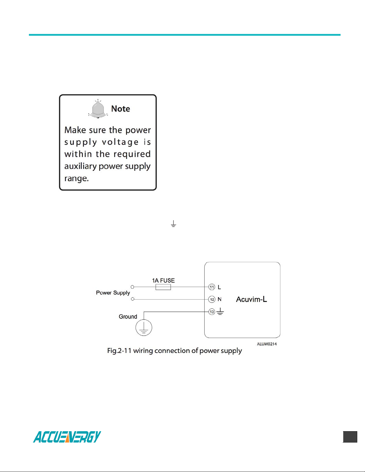
2.3.2 Power Requirement
Auxiliary power
There are two Auxiliary Power Supply options for
the Acuvim-L series meter:
1. Standard: 100~415Vac (50/60Hz) or 100~300Vdc
2. Low Voltage DC Option: 20-60Vdc
Choose the option according to the application.
The meter’s typical power consumption is very low
and can be supplied by an independent source or
by the measured load line. A regulator or an
uninterrupted power supply (UPS) should be used
under high power fluctuation conditions. Terminals
for the auxiliary power supply are 11, 12 , 13 (L, N,
).
The typical wiring connection is shown as Fig.2-11.
Find Quality Products Online at: sales@GlobalTestSupply.com
The wire of power supply should be AWG22-16 or 0.6-1.3mm2 . A fuse (typical 1A/250Vac)
should be used in the auxiliary power supply loop. No.13 terminal must be connected to the
ground terminal of switchgear. An isolated transformer or EMC filter should be used in the
auxiliary power supply loop if there is a power quality problem in the power supply.
www.GlobalTestSupply.com
Page 24

Acuvim-L Series Power Meter
Chapter 2 Installation
V:2.0 Revised October 2018
24
Voltage Input
Maximum input voltage for the Acuvim-L series meter shall not exceed 400LN/690LL VAC rms
for three phase or 400LN VAC rms for single phase. Potential Transformer (PT) must be used
for high voltage systems. Typical secondary output for PTs shall be less than or equal to 400V.
Please make sure to select an approprate PT to maintain the measurement accuracy of the
meter.
A fuse (typical 1A) should be used in the voltage input
loop. The wire for voltage input could be AWG16-12 or
1.3-2.0mm2.
Note: In no circumstance should the secondary of the
PT be shorted. The secondary the PT should be
grounded at one end.
Please refer to the wiring diagram section for further
details.
Current Input
Current Transformers (CTs) are required in most engineering applications. Typical current
rating for the secondary side of the CT shall be 5A (standard) or 1A (optional, please refer to
the ordering information appendix for further details). CTs must be used if the system rated
current is over 5A. The accuracy of the CT should be better than 0.5% with rating over 3VA is
recommended in order to preserve the meter’s accuracy. The wire between CTs and the
meter shall be as short as possible. The length of the wire may increase the error of the
measurement.
Find Quality Products Online at: sales@GlobalTestSupply.com
www.GlobalTestSupply.com
Page 25

Acuvim-L Series Power Meter
Chapter 2 Installation
V:2.0 Revised October 2018
25
The wire size of current input could be AWG15-16 or 1.5-2.5mm2.
Note: The secondary side of the CT should not be open circuit in any circumstance when the
power is on. There should not be any fuse or switch in the CT loop. One end of the CT loop
should be connected to the ground.
Vn connection
Vn is the reference point of the Acuvim-L voltage input. Low wire resistance helps improve
the measurement accuracy. Different system wiring modes require different Vn connection
method. Please refer to the wiring diagram section for more details.
Three phase wiring diagram
Acuvim-L can satisfy almost all kinds of three phase wiring diagram. Please read this section
carefully before choosing the wiring diagram suitable for your power system.
Voltage and current input wiring mode can be set separately in the meter parameter setting
process. The voltage wiring mode can be set as 3-phase 4-line Wye(3LN), 3-phase 3-line
direct connection mode(3LL), 3-phase 3-line open delta (2LL), single-phase two-line(1LN)
and single-phase three-line(1LL). The current input wiring mode can be set as 3CT, 2CT and
1CT. Any voltage wiring setup can be matched with any one of the current wiring setup.
2.3.3 Voltage Input Wiring
3-Phase 4-Line Wye mode (3LN)
The 3-Phase 4-Line Wye mode is popularly used in low voltage electric distribution power
system. For voltage lower than 400LN/690LL Vac, power line can be connected directly to
the meter’s voltage input port as shown in Fig.2-13a. In the high voltage input system, 3PT
Wye mode is often used as in Fig.2-13b. The meter should be set to 3LN for both voltage
levels.
Find Quality Products Online at: sales@GlobalTestSupply.com
www.GlobalTestSupply.com
Page 26

Acuvim-L Series Power Meter
Chapter 2 Installation
V:2.0 Revised October 2018
26
3-Phase 3-Line Direct Connection Mode (3LL)
In a 3-Phase 3-Line system, power line A, B and C are connected to V1, V2 and V3
directly. Vn is floated. The voltage input mode of the meter should be set to 3LL.
Find Quality Products Online at: sales@GlobalTestSupply.com
www.GlobalTestSupply.com
Page 27

Acuvim-L Series Power Meter
Chapter 2 Installation
V:2.0 Revised October 2018
27
3-Phase 3-Line open Delta Mode (2LL)
Open delta wiring mode is often used in high voltage system. V2 and Vn connected
together in this mode. The voltage input mode of the meter should be set to 2LL for
this voltage input wiring mode.
Find Quality Products Online at: sales@GlobalTestSupply.com
www.GlobalTestSupply.com
Page 28

Acuvim-L Series Power Meter
Chapter 2 Installation
V:2.0 Revised October 2018
28
2.3.4 Current Input Wiring
3CT
The 3CT current wiring configuration can be used when either 3CTs are connected (as
shown in Fig.2-16) or 2CTs are connected (as shown in Fig.2-17) to the system. In either
case, there is current flowing through all three current terminals.
Find Quality Products Online at: sales@GlobalTestSupply.com
www.GlobalTestSupply.com
Page 29

Acuvim-L Series Power Meter
Chapter 2 Installation
V:2.0 Revised October 2018
29
2CT
The difference between Fig.2-17 and Fig.2-18 is that no current flows through current
input terminal I21 and I22. The I2 value is calculated from formula i1+i2+i3=0. The
current input mode of the meter should be set to 2CT .
1CT
The current input mode of the meter should be set to 1CT
Find Quality Products Online at: sales@GlobalTestSupply.com
www.GlobalTestSupply.com
Page 30

Acuvim-L Series Power Meter
Chapter 2 Installation
V:2.0 Revised October 2018
30
2.3.5 Frequently Used Wiring Method
In this section, most common voltage and current wiring connection combinations are
put together into different diagrams. In order to display measurement readings correctly,
please select the appropriate wiring diagram according your setup and application.
Note: Acuvim-L supports 3LN-3CT (Using the 3CT and a 2CT two wiring), 3LL-3CT, 2LL3CT, 2LL-2CT, 1LL-2CT and 1LN-1CT.
1. 3LN, 3CT with 3 CTs (Wiring mode: 3LN, 3CT)
Find Quality Products Online at: sales@GlobalTestSupply.com
www.GlobalTestSupply.com
Page 31

Acuvim-L Series Power Meter
Chapter 2 Installation
V:2.0 Revised October 2018
31
2. 3LN, 3CT with 2 CTs (Wiring mode: 3LN,3CT)
3. 3LL,3CT (Wiring mode:3LL,3CT)
Find Quality Products Online at: sales@GlobalTestSupply.com
www.GlobalTestSupply.com
Page 32

Acuvim-L Series Power Meter
Chapter 2 Installation
V:2.0 Revised October 2018
32
4. 2LL, 3CT (Wiring mode: 2LL, 3CT)
5. 2LL, 2CT (Wiring mode: 2LL, 2CT)
Find Quality Products Online at: sales@GlobalTestSupply.com
www.GlobalTestSupply.com
Page 33

Acuvim-L Series Power Meter
Chapter 2 Installation
V:2.0 Revised October 2018
33
6. 1LL, 2CT (Wiring mode setting 1LL, 2CT)
7. 1LL, 2CT (Wiring mode setting 1LL, 2CT)
Note: For the 1LL, 2CT, A and B facies of the phase Angle is 1800.
Find Quality Products Online at: sales@GlobalTestSupply.com
www.GlobalTestSupply.com
Page 34

Acuvim-L Series Power Meter
Chapter 2 Installation
V:2.0 Revised October 2018
34
2.3.6 Digital Output (DO)
There are two digital outputs for Acuvim-L. For the Acuvim-BL, the terminals of the
digital output are DO1, DO2 and DOC . For the Acuvim-DL/EL, the terminals
of the digital output respectively is DO11, DO12 and DO21, DO22.These two digital
outputs can be used as energy pulse output or over/under limit alarming output.
Digital output circuit form is Photo-MOS. The simplified circuit is as below:
The max output voltage and current are 250Vac/300Vdc and 100mA. When the digital
output is used as over/under limit alarming output, the upper and lower limit of the
parameter, time interval and output port can be set from the meter front.
Find Quality Products Online at: sales@GlobalTestSupply.com
www.GlobalTestSupply.com
Page 35

Acuvim-L Series Power Meter
Chapter 2 Installation
V:2.0 Revised October 2018
35
2.3.7 Digital Input (DI)
There are 4 dry-contact digital input in extension modules respectively. The digital
input circuit can be used to detect remote signals, or be used as a counter of input
pulses.
The circuit drawing of digital input is simplified as fig.2-28. When K is switched off,
OUT is in high state. When K is switched on, OUT is in low state. The wire of digital
input should be chosen between AWG22~16 or 0.5~1.3mm2.
2.3.8 Communication
Acuvim-L series meter uses RS485 serial communication and the ModbusRTU
protocol. The terminals of communication are A, B, and S (14, 15 and 16). A is
differential signal +, B is differential signal - and S is connected to the shield of twisted
pair cable. Up to 32 devices can be connected on a RS485 bus. Use good quality
shielded twisted pair cable, AWG22 (0.5mm2) or larger. The overall length of the
RS485 cable connecting all devices can not exceed 1200m (4000ft). Acuvim-L series
meter can be used as a slave device of a master device such as PC, PLC, Data Collector
and RTU.
Find Quality Products Online at: sales@GlobalTestSupply.com
www.GlobalTestSupply.com
Page 36

Acuvim-L Series Power Meter
Chapter 2 Installation
V:2.0 Revised October 2018
36
If the master does not have RS485 communication port, a converter (such as a
RS232/RS485 or a USB/RS485 converter) will be required. Typical RS485 network
topologies include line, circle and star (wye).
Data transfer format is start bit + 8 data bits + parity + stop bit. NON1, NON2, odd and
EVEN could be selected in the mode of parity. NON1 represents non-parity, single stop
bit; NON2 represents non-parity, double stop bit; odd represents odd parity, single
stop bit; EVEN represents EVEN-parity, single stop bit.
All meter has been standardized. In order to improve the quality of communications,
now offers the following Suggestions:
The shield of the RS485 cable must be connected to the ground at one end only. Every
A(+) should be connected to A(+), B(-) to B(-), or it will influence the network, even
damage the communication interface.
“T” type connection topology should be avoided. This means no new branches except
from the starting point.
Keep communication cables away as much as possible from sources of electrical noise.
When several devices are connected (daisy chain) to the same long communication
line, an anti signal reflecting resistor (typical value 120Ω- 300Ω/ 0.25W) is often used
at the end of the circuit (the last meter of the chain) if the communication quality is
distorted.
Use RS232/RS485 or USB/RS485 converter with optical isolated output and surge
protection.
Find Quality Products Online at: sales@GlobalTestSupply.com
www.GlobalTestSupply.com
Page 37

Acuvim-L Series Power Meter
Chapter 2 Installation
V:2.0 Revised October 2018
37
Acuvim-L Series Power Meter
Chapter 3: Meter Operation and Parameter Setting
3.1 Display Panel and Keys
3.2 Metering Data
3.3 Statistics Display
3.4 System Parameter Setting
3.5 DO Parameter Setting and Expansion Module Setting
3.6 Ethernet Network Module Settings
3.7 DI Status Display
3.8 TOU Energy and Maximum Demand Display
3.9 Measurement Methods and Parameters Definitions
Find Quality Products Online at: sales@GlobalTestSupply.com
www.GlobalTestSupply.com
Page 38

Acuvim-L Series Power Meter
Chapter 3: Meter Display and Parameter Settings
V:2.0 Revised October 2018
38
Chapter 3: Meter Display and Parameter Settings
Operational details of the meter will be described in this chapter. This includes viewing realtime metering data and setting parameters using different key combination.
3.1 Display Panel and Keys
The front of the Acuvim-L series meter consists of an LCD screen and four control keys. All
display segments are shown as Fig.3-1 below:
Find Quality Products Online at: sales@GlobalTestSupply.com
www.GlobalTestSupply.com
Page 39

Acuvim-L Series Power Meter
Chapter 3: Meter Display and Parameter Settings
V:2.0 Revised October 2018
39
SN
Display
Description
1
Three lines of " " digits in the
metering area
Display metering data Voltage, current, power,
power factor, THD, frequency, demand,
unbalance factor, max, min etc.
2
Status display area One line of " "
digits at the top of display panel
Display current status Meter: metering status;
Max: maximum value; Min: minimum value;
THD: display Har: display individual harmonic
for voltage and current.
3
Item icon
Item icon
U: voltage; I: current, P: active power; q:
reactive power; PF: power factor; when
displaying harmonic content, the little "8" digits
show the harmonic order.
4
3-phase unbalance
Unbalance icon
5
Load nature
: inductive load;
: capacitive load.
6
Energy Icon
Imp: import energy; exp: export energy
7
Communication icon
No icon: no communication
With icon: communication
8
Energy pulse
output indicator
No icon: no pulse output
With icon: pulse output
9
Time icon
With icon: display running time
10
Units
Indicate data unit
Voltage: V, kV, Current: kA, A, Power: kW and
MW, Reactive Power: kvar and Mvar, Apparent
Power: kVA and MVA, Frequency: Hz, Energy:
kWh, Reactive Power: kvarh, Percentage: %
There are four dedicated keys on the front panel, labeled H, P, E and V/A from left to right.
Use these four keys to read metering data and set the parameters.
Note: If the LCD backlight is off, press any key one time to bring the backlight on
Find Quality Products Online at: sales@GlobalTestSupply.com
www.GlobalTestSupply.com
Page 40

Acuvim-L Series Power Meter
Chapter 3: Meter Display and Parameter Settings
V:2.0 Revised October 2018
40
The 1st screen: Voltage for each phase: U1,
U2 and U3. As shown in Fig.3-2, U1=380.2
V, U2=380.0 V, U3=379.8 V.
Load nature is inductive, and
communication status is good.
Note: Since load nature and
communication status belong to system
information, the icons are displayed on
every screen.
3.2 Metering Data
Acuvim-L series meter displays the voltage metering screen (default screen) when first
powered up. Different key combinations show different screen. Press “V/A” to show realtime metering data; press “E” to show energy parameters; press “P” to show power
parameters; press “H” to show power quality information; press “H” and “E” together
simultaneously to show max/min information, unbalance and individual harmonics.
Press “H” and “V/A” together simultaneously to show basic parameter setting.
Press “P” and “V/A” together simultaneously to show DI Status. Press “E” and “V/A”
together simultaneously to show TOU Energy.
Note: No harmonic contents will be displayed in Acuvim-EL and Acuvim-KL.
Press “V/A” to read voltage and current in the metering area. The screen will proceed to
the next display as you press “V/A” each time. It will go back to the first screen if you press
“V/A” at the last screen.
Find Quality Products Online at: sales@GlobalTestSupply.com
www.GlobalTestSupply.com
Page 41

Acuvim-L Series Power Meter
Chapter 3: Meter Display and Parameter Settings
V:2.0 Revised October 2018
41
Press “V/A” to go to the next screen.
The 2nd screen: Line to line voltage: U12,
U23 and U31. As shown in Fig.3-3,
U12=658.5 V, U23=658.0 V, U31=657.8 V.
Press “V/A” to go to the next screen.
The 3rd screen: Current for each phase: I1,
I2 and I3. As shown in Fig. 3-4, I1=2.501 A,
I2=2.500 A, I3=2.499 A.
Press “V/A” to go to the next screen.
The 4th screen: Neutral current. As shown
in Fig.3-5, In=0.000 A.
Press “V/A” to go to the next screen.
Find Quality Products Online at: sales@GlobalTestSupply.com
www.GlobalTestSupply.com
Page 42

Acuvim-L Series Power Meter
Chapter 3: Meter Display and Parameter Settings
V:2.0 Revised October 2018
42
The 5th screen: Current demand of each
phase.
As shown in Fig.3-6, Dmd_I1=2.503 A,
Dmd_I2=2.501 A, Dmd_I3=2.500 A.
Press “V/A” to go back to the 1st screen.
The 5th screen: Current demand of each
phase.
As shown in Fig.3-6, Dmd_I1=2.503 A,
Dmd_I2=2.501 A, Dmd_I3=2.500 A.
Press “V/A” to go back to the 1st screen.
Note: For Acuvim-KL, only the current page is displayed. When the wiring mode is set to 3LL3CT,2LL-3CT or 2LL-2CT, it will not display phase voltage and neutral current, there is no the
1st and 4th screen. When the wiring mode is set to 1LL2CT, it only shows Uab of 2nd screen,
Ia and Ib of 3rd screen. When the wiring is 1LL-1CT, it only shows Ua of 1st screen and Ia of
3rd screen, not display line voltage and neutral current, there is no the 2nd and 4th screen.
Press “P” to display power related parameters.
Find Quality Products Online at: sales@GlobalTestSupply.com
www.GlobalTestSupply.com
Page 43

Acuvim-L Series Power Meter
Chapter 3: Meter Display and Parameter Settings
V:2.0 Revised October 2018
43
The 2nd screen: Reactive power of each
phase.
As shown in Fig.3-8, Q1=0.823 kvar,
Q2=0.823 kvar, Q3=0.822 kvar.
Press “P”, go to the next screen.
Go back to the 1st screen.
The 3rd screen: Apparent power of each
phase.
As shown in Fig.3-9, S1=0.950 kVA,
S2=0.951 kVA, S3=0.950 kVA.
Press “P” to go to the next screen.
The 4th screen: System total power,
reactive power and apparent power.
As shown in Fig.3-10, Psum=1.426 kW,
Qsum=2.471 kvar, Ssum=2.853 kVA.
Press “P” to go to the next screen.
Find Quality Products Online at: sales@GlobalTestSupply.com
www.GlobalTestSupply.com
Page 44

Acuvim-L Series Power Meter
Chapter 3: Meter Display and Parameter Settings
V:2.0 Revised October 2018
44
The 5th screen: Power factor of each
phase: PF1,PF2, PF3.
As shown in Fig.3-11, PF1=0.500,
PF2=0.499, PF3=0.500.
Press “P” to go to the next screen.
The 6th screen: System average power
factor PF and system frequency F.
As shown in Fig.3-12, PF=0.500, F=50.01 Hz.
Press “P” to go to the next screen.
The 7th screen: System power demand
Dmd_P, reactive power demand Dmd_Q
and apparent power demand Dmd_S.
As shown in Fig.3-13, Dmd_P=1.425 kW,
Dmd_Q=2.472 kvar, Dmd_S = 2.850 kVA.
Press “P” to go to the next screen.
Find Quality Products Online at: sales@GlobalTestSupply.com
Note: For Acuvim-KL, only display system power, When the wiring is set to 3LL-3CT, 2LL-3CT
and 2LL-2CT, it will not show single-phase active power of 1st, two single-phase reactive
power of 2nd, single-phase apparent power of 3rd and single-phase power factor of 5th.
www.GlobalTestSupply.com
Page 45

Acuvim-L Series Power Meter
Chapter 3: Meter Display and Parameter Settings
V:2.0 Revised October 2018
45
The 1st screen: Import energy
As shown in Fig. 3-14, Ep_imp=50.9 kWh.
Press “E”, go to the next screen.
The 2nd screen: Export energy.
As shown in Fig. 3-15, Ep_exp=1.8 kWh.
Press “E”, go to the next screen.
The 3rd screen: Inductive (import) reactive
energy.
As shown in Fig. 3-16, Eq_imp=3.9 kvarh.
Press “E” to go to the next screen.
For other series meters, if the wiring is set to 2LL, or 3LL, there is no single-phase power and
single-phase power factor displayed, press P to switch between screens only 4,6,7.
Find Quality Products Online at: sales@GlobalTestSupply.com
www.GlobalTestSupply.com
Page 46

Acuvim-L Series Power Meter
Chapter 3: Meter Display and Parameter Settings
V:2.0 Revised October 2018
46
The 4th screen: Capactive (export) reactive
energy.
As shown in Fig. 3-17, Eq_exp=1.5 kvarh.
Press “E” to go to the next screen.
The 5th screen: Apparent energy.
As shown in Fig.3-18, Es = 3.0kVAh.
Press “E” to go to the next screen.
The 6th screen: Run hours.
As shown in Fig.3-19, Run_Hour=12.3
hours.
Press “E” to go to the next screen.
Find Quality Products Online at: sales@GlobalTestSupply.com
www.GlobalTestSupply.com
Page 47

Acuvim-L Series Power Meter
Chapter 3: Meter Display and Parameter Settings
V:2.0 Revised October 2018
47
The 7th screen: Load Run hours.
As shown in Fig.3-20, Load Run hour = 1.3
hours.
Press “E” to go to the next screen.
Note: This screen only applies to Acuvim-DL, EL
and KL.
Note: In real-time metering mode, Acuvim-AL, Acuvim-BL, Acuvim-CL, Acuvim-DL and
Acuvim-EL display voltage and current THD when “H” is pressed.
The 1st screen: Voltage THD.
When voltage wiring mode is set to 3LN, display
shows phase voltage THD: THD_U1, THD_U2,
THD_U3.
As shown in Fig. 3-21, THD_U1=2.32%,
THD_U2=2.35%, THD_U3=2.28%.
When voltage wiring mode is set to 2LL or 3LL, display shows line to line voltage THD:
THD_U12, THD_U23, THD_U31.
As shown in Fig.3-22, THD_U12=2.30%,
THD_U23=2.28%, THD_U31=2.25%.
When voltage wiring mode is set 1LN, display
only shows phase voltage THD: THD-U1. When
voltage wiring mode is set 1LL, display only
shows phase voltage THD: THD-U1 and THD-U2.
Press “H” to go to the next screen.
Find Quality Products Online at: sales@GlobalTestSupply.com
www.GlobalTestSupply.com
Page 48

Acuvim-L Series Power Meter
Chapter 3: Meter Display and Parameter Settings
V:2.0 Revised October 2018
48
The 2nd screen: Phase current THD: THD_I1,
THD_I2, THD_I3.
As shown in Fig 3-23, THD of three phase
current, THD_I1=1.89%, THD_I2=1.83%,
THD_I3=1.85%.
Press “H” key, go back to the 1st screen.
Press “V/A” key under the statistics display
mode to display the Min and Max value of
voltage, current and current demand.
The 1st screen: Max value of phase voltage. The
“Max” icon is shown on the top of screen.
As shown in Fig. 3-24, U1_MAX=380.3 V,
U2_MAX=380.2 V, U3_MAX=380.5 V.
Note: When voltage wiring mode is set to 1LN, display only shows phase current THD: THDI1. When voltage wiring mode is set to 1LL, display only shows phase current THD: THD-I1
and THD-I2.
3.3 Statistics Display
For Acuvim-AL,BL,CL,DL,ELPress “H” and “E” simultaneously to enter the statistic display
mode. Maximum and minimum value for metering parameters are
demand, voltage and current unbalance factor, and individual voltage and current harmonic.
Press “H” and “E” simultaneously again to exit to the real-time metering mode.
Note: Acuvim-EL and Acuvim-KL will not show harmonic contents.
3.3.1 Display Max and Min of the voltage and current and Peak Demand of current. (AL,
BL, CL, DL, EL)
Find Quality Products Online at: sales@GlobalTestSupply.com
www.GlobalTestSupply.com
Page 49

Acuvim-L Series Power Meter
Chapter 3: Meter Display and Parameter Settings
V:2.0 Revised October 2018
49
The 2nd screen: MIN value of phase
voltage. The “MIN” icon shown on the top
of screen.
As shown in Fig.3-25, U1_MIN=379.6 V,
U2_MIN=379.8 V, U3_MIN=379.7 V.
Press “V/A” to go to the next screen.
The 3rd screen: Max value of line to line
voltage.
As shown in Fig 3-26, U12_MAX=658.6 V,
U23_MAX=658.3 V, U31_MAX=658.3 V.
Press “V/A” to go to the next screen.
The 4th screen: MIN value of line to line
voltage.
As shown in Fig.3-27, U12_MIN=657.8 V,
U23_MIN=657.7 V, U31_MIN=657.6 V.
Press “V/A” to go to the next screen.
Find Quality Products Online at: sales@GlobalTestSupply.com
www.GlobalTestSupply.com
Page 50

Acuvim-L Series Power Meter
Chapter 3: Meter Display and Parameter Settings
V:2.0 Revised October 2018
50
The 5th screen: MAX value of current.
As shown in Fig.3-28, I1_MAX=2.502 A ,
I2_MAX=2.503 A, I3_MAX=2.502 A .
Press “V/A” to go to the next screen.
The 6th screen: MIN value of current.
As shown in Fig.3-29, I1_MIN=2.498 A,
I2_MIN=2.496 A, I3_MIN=2.497 A.
Press “V/A” to go to the next screen.
The 7th screen: Peak current demand.
As shown in Fig 3-30, I1_Demand_MAX=2.505
A, I2_Demand_MAX=2.504 A, I3_Demand_
MAX=2.504 A.
When voltage wiring mode is set to1LN, display only shows first line of 1st, 2nd, 5th, 6th and
7th screen. When voltage wiring mode is set to 1LL, display only shows first and second line
line of 1st, 2nd, 5th, 6th and 7th screen, and first line of 3rd and 4th. When voltage wiring
mode is set to 2LL or 3LL, display doesn’t show the 1st and 2nd screen.
Press “V/A” to go back to the first screen.
Find Quality Products Online at: sales@GlobalTestSupply.com
www.GlobalTestSupply.com
Page 51

Acuvim-L Series Power Meter
Chapter 3: Meter Display and Parameter Settings
V:2.0 Revised October 2018
51
The 7th screen: Peak current demand.
As shown in Fig 3-30, I1_Demand_MAX=2.505
A, I2_Demand_MAX=2.504 A, I3_Demand_
MAX=2.504 A.
The 1st screen: Unbalance factor for voltage
and current.
As shown in Fig.3-32, voltage unbalance
factor=0.3%, current unbalance factor=0.5%.
Press “H” to go to the next screen.
3.3.2 Display the Max value of power and reactive power demand.
Press “P” under the statistics display mode to display the peak value for power, reactive
power and apparent power demand.
3.3.3 Display power quality parameter (AL, BL, CL, DL, EL)
When press “H” under statistic display mode, will display voltage and current unbalance
factor as well as individual voltage and current harmonic content.
Press “H” key to display voltage and current harmonic content. The HAR icon will be shown
on the top of the screen. The sequence will roll starting from the 2nd harmonic of voltage to
the 15th harmonic of current as you press “H” each time. The following shows the display for
phase voltage, line to line voltage and current harmonic contents.
Find Quality Products Online at: sales@GlobalTestSupply.com
www.GlobalTestSupply.com
Page 52

Acuvim-L Series Power Meter
Chapter 3: Meter Display and Parameter Settings
V:2.0 Revised October 2018
52
The 2nd screen: 2nd harmonic content of
voltage.
As shown in Fig.3-33, U1_Hr2=0.12%,
U2_Hr2=0.14%, U3_Hr2=0.12%.
Press H to scroll through the 3rd to the 31th
phase voltage harmonic content
Note: When voltage wiring of the meter is set to 2LL or 3LL, line to line voltage harmonic
contents will be display instead (as shown in Fig. 3-34).
The 2nd screen: 2nd harmonic content of line to
line voltage.
As shown in Fig.3-34, U12_Hr2=0.12%,
U23_Hr2=0.14%, U31_Hr2=0.12%.
Press H to scroll through the 3rd to the 31th line
to line voltage harmonic content.
The 33th screen: 2nd harmonic content of
current.
As shown in Fig.3-35, I1_Hr2=3.08%,
I2_Hr2=3.05%, I3_Hr2=3.01%.
Press “H” key to scroll through the 3rd to the
31th current harmonic content.
In the statistic mode, press “H” and “E”
simultaneously to exit this mode.
Find Quality Products Online at: sales@GlobalTestSupply.com
Note: When voltage wiring mode is set to 1LL, the screen only shows the first line and the
second line; when set to 1LN, this screen only displays the first line.
www.GlobalTestSupply.com
Page 53

Acuvim-L Series Power Meter
Chapter 3: Meter Display and Parameter Settings
V:2.0 Revised October 2018
53
3.4 System Parameter Setting
Press “H” and “V/A” simultaneously in the metering data display mode to enter the system
parameter setting mode. All the settings can be done through the keys on the meter front
panel.
Press “H” to move the flashing cursor to the right, press “P” to increase the number by 1 once
a time, press “E” to decrease the number by 1 once a time, press “V/A” to accept the change
and move to the next screen. Press “H” and “V/A” simultaneously to exit system parameter
setting mode and return to real-time metering mode.
System parameter setting mode is password protected, a four digit password (select from
0000 to 9999) is required every time before accessing the system parameter settings. The
default password is 0000. After entering the password, press “V/A” to accept the password
and proceed. The meter will return to the real-time metering mode if a wrong password is
entered.
Find Quality Products Online at: sales@GlobalTestSupply.com
www.GlobalTestSupply.com
Page 54

Acuvim-L Series Power Meter
Chapter 3: Meter Display and Parameter Settings
V:2.0 Revised October 2018
54
The 1st screen: Communication Address
setting.
The address can be any integer between 1 -
247. As shown in Fig.3-37, the communication
address is 1.
To change the address, press “H” to move the
cursor, press “P” to increase value by 1, press
“E” to decrease value by 1. Press “V/A” to
store the current address and go to the next
setting screen. Press “V/A” to proceed to the
next screen if there is no need to change the
address.
Note: Meters cannot have the same communication address on the same RS485
communication line according to the Modbus-RTU protocol.
The 2nd screen: Baud rate setting.
The asynchronous communication setting of
Acuvim-L is 8-bit, parity, 1 start bit and 1 or 2
stop bits. Baud rate can be set as follows:
1200, 2400, 4800, 9600, 19200, 38400,
57600. Press “P” or “E” to select a suitable
baud rate. Press “V/A” to accept the change
and proceed to the next screen. Same baud
rate should be used for all meter connecting
on the same communication line.
Find Quality Products Online at: sales@GlobalTestSupply.com
www.GlobalTestSupply.com
Page 55

Acuvim-L Series Power Meter
Chapter 3: Meter Display and Parameter Settings
V:2.0 Revised October 2018
55
The 3rd screen: communication check
setting. communication check could be one
of four settings: non1, non2, odd, EVEN. As
shown in Fig.3-39: communication check is
set to non1.
Press “P” or ”E” to select a communication
check mode, press “V/A” to accept the
change and processed to the next page.
The 4th screen: Voltage input wiring setting.
Voltage input could be one of five setting: 3LN,
3LL, 2LL, 1LL, 1LN.
As shown in Fig.3-40: voltage input mode is set
to 3LN.
Press “P” or “E” to select a wiring mode, press
“V/A” to accept the change and proceed to the
next page.
The 5th screen: Current input wiring setting.
Current wiring mode can be one of the three
settings: 3CT, 2CT, 1CT. As shown in Fig.3-41,
current input mode is set to 3CT
Press “P” or “E” to select a wiring mode, press
“V/A” to accept the change and proceed to the
next page.
Note: The page is only shown in Acuvim-EL and KL. “non1” represents non-parity, single
stop bit; “non2” represents non-parity, double stop bit; “odd” represents odd-parity, single
stop-bit; “EVEN” represents even parity, single stop bit. By default, it is set as “EVEN”.
Find Quality Products Online at: sales@GlobalTestSupply.com
www.GlobalTestSupply.com
Page 56

Acuvim-L Series Power Meter
Chapter 3: Meter Display and Parameter Settings
V:2.0 Revised October 2018
56
The 6th screen: PT primary side ratio setting. PT1
ratio can be set from 50.0 to 1,000,000.0 (unit in
V)
As shown in Fig.3-42, PT1=380.0V.
To change PT1 value, press “H” to move the
cursor, press “P” to increase value by 1, press “E”
to decrease value by 1. Press “V/A” to store the
current value and proceed to the next screen.
The 7th screen: PT secondary side ratio setting.
PT2 ratio can be set from 50.0 to 400.0 (unit in
V).
As shown in Fig.3-43, PT2=380.0V.
To change PT2 value, press “H” to move the
cursor, press “P” to increase value by 1, press
“E” to decrease value by 1. Press “V/A” to store
the current value and proceed to the next
screen.
Note: If no PT is installed at the voltage input, PT1 and PT2 should be the same and equal
to the input rated voltage.
The 8th screen: CT primary side ratio setting.
CT1 ratio can be set from 5 to 50000 (unit in A).
For a 1A option meter, CT1 can be set from 1 to
50000 (unit in A).
As shown in Fig.3-44, CT1=5A.
To change CT1 value, press “H” to move the
cursor, press “P” to increase value by 1, press “E”
to decrease value by 1. Press “V/A” to store the
current value and proceed to the next screen.
Find Quality Products Online at: sales@GlobalTestSupply.com
www.GlobalTestSupply.com
Page 57

Acuvim-L Series Power Meter
Chapter 3: Meter Display and Parameter Settings
V:2.0 Revised October 2018
57
Note: CT1 has two-digit lines representing one figure. For example, if CT primary is 200,
CT1 should be programmed as 0020 for the top line, and 0 for the bottom line, so that it
is read as 200.
The 9th screen: CT secondary side ratio setting.
CT2 can be 1, 5 and 333; user can modify the
CT2 as 1 or 5, if CT2=333mv, it cannot be
modified.
As shown in Fig.3-45, CT1=5A, Press “V/A” to
proceed to the next page.
The 10th screen: Definition of reactive power.
0: sinusoidal reactive power;
1: budeanu’s reactive power.
Please refer to Chapter 3.6 <<Measurement
methods and parameter definitions>> for
details.
Find Quality Products Online at: sales@GlobalTestSupply.com
www.GlobalTestSupply.com
Page 58

Acuvim-L Series Power Meter
Chapter 3: Meter Display and Parameter Settings
V:2.0 Revised October 2018
58
The 11th screen: Backlight “ON” time setting.
The “ON” time can be set from 0 to 120
minute.
The LCD screen backlight will always be “ON” if
the setting value is 0. The backlight will turn
“OFF” after inactive for a period of time if other
value (from 1to 120) is set.
As shown in Fig.3-47, the setting time of the
backlight is 2 minutes. The backlight will
automatically turn “OFF” if no key activation
within 2 minutes.
The 12th screen: Sliding windows time for
demand setting.
Sliding windows time of demand can be set
from
1-30 minute. The window slides once per
minute.
As shown in Fig.3-48, the sliding windows time
is 8 minutes.
Find Quality Products Online at: sales@GlobalTestSupply.com
www.GlobalTestSupply.com
Page 59

Acuvim-L Series Power Meter
Chapter 3: Meter Display and Parameter Settings
V:2.0 Revised October 2018
59
The 13th screen: Clear Max and Min page
setting.
To clear Max and Min values do not mean
writing 0 to all of the registers. Meter’s current
metering values will be copied to the statistic
registers instead and start a new statistic
period.
Press “P” or “E” to select “YES” or “NO”:
“YES”: clear Max and Min;
“NO”: do not clear Max and Min.
Press “V/A” accept selection and proceed to the
next page.
The 14th screen: Clear energy enable setting
page.
This screen enables the energy reset function of
the meter.
1: enable; 0: disable.
The 15th screen: Acknowledgement to
clear energy setting.
This screen appears only when the 14th
screen is set as “enable”.
Press “E” or “P” to select “YES” or “NO”:
“YES”: clear energy;
“NO”: do not clear energy.
Find Quality Products Online at: sales@GlobalTestSupply.com
www.GlobalTestSupply.com
Page 60

Acuvim-L Series Power Meter
Chapter 3: Meter Display and Parameter Settings
V:2.0 Revised October 2018
60
All energy parameters will be set to 0 when “YES” is selected. Press “V/A” to accept
selection and proceed to the next page.
The 16th screen: Clear running time setting.
Press “P” or “E” to select “YES” or “NO”:
“Yes”: clear running time;
“No”: do not clear running time.
Running time will be set to 0 when “YES” is
selected. Press “V/A” to accept selection
and proceed to the next page.
The 17th screen: Clear load running time
setting. the page would display. Press “P”
or “E” to select “YES” or “NO”: “Yes”: clear
running time. “No”: do not clear running
time. Running time will be set
to 0 when “YES” is selected. Press” V/A” to
accept selection and proceed to next page.
Find Quality Products Online at: sales@GlobalTestSupply.com
www.GlobalTestSupply.com
Page 61

Acuvim-L Series Power Meter
Chapter 3: Meter Display and Parameter Settings
V:2.0 Revised October 2018
61
The 18th screen: VAR/PF setting. Press “P” or
“E” to change VAR/PF setting.
As shown in Fig.3-54 is IEC standard.
Note: The page would be show only in
Acuvim-EL.
The 19th screen: Password setting. This is the
last screen in system parameter setting mode.
The password can be changed in this page. It
is important to remember the new password.
As shown in Fig.3-55, the password is 0001.
Press “V/A” to store the new password and
return to the first setting page. Press “H” and
“V/A” together to exit the system setting
mode after finishing all of the settings.
3.5 DO Parameter Setting and Expansion Module Setting (BL, DL, EL)
Acuvim-BL meter has two digital outputs. Each can operate as energy pulse output or alarm
output. All DO parameters can be set from the meter front. To distinguish with system
parameter setting mode, we call this setting mode as DO parameter setting mode.
Press “P” key and “E” key simultaneously under system parameter setting mode to enter DO
parameter setting mode. Press “H” to move the flashing cursor to the right, press “P” to
increase the number by 1 once a time, press “E” to decrease the number by 1 once a time,
press “V/A” to accept the change and move to the next screen. Press “P” and “E”
Find Quality Products Online at: sales@GlobalTestSupply.com
simultaneously to exit DO parameter setting mode and return to system parameter setting
mode.
www.GlobalTestSupply.com
Page 62

Acuvim-L Series Power Meter
Chapter 3: Meter Display and Parameter Settings
V:2.0 Revised October 2018
62
The 1st screen: Extend IO baud rate setting.
Extend IO Baud rate can be set as follows:
1200, 2400,4800, 9600, 19200, 38400,
57600. Press “P” or “E” to select a suitable
baud rate. Press “V/A” to accept the change
and proceed to the next screen. Same baud
rate should be used for all meters
connecting on the same communication
line.
Note: The page would be shown only in
AcuvimDL and Acuvim-EL.
The 2nd screen: Extend IO communication
check setting. Extend IO communication
check could be one of four settings: NON1,
NON2, odd, EVEN. As shown in Fig.3-57:
Extend IO communication
check is set to NON1.
Press “P” or ”E” to select a communication
check mode, press “V/A” to accept the
change and processed to the next page.
Note: The page would be shown only in
AcuvimEL.
If the extend IO module could be added, it contains 2 DO, 4 DI and communication with
Modbus-RTU standard. Press “P” key and “E” key simultaneously under system parameter
setting mode to enter DO parameter setting and Extend IO communication setting mode, the
operation about key is same as Acuvim-BL DO setting. The following steps show how to set
DO items:
Find Quality Products Online at: sales@GlobalTestSupply.com
www.GlobalTestSupply.com
Page 63

Acuvim-L Series Power Meter
Chapter 3: Meter Display and Parameter Settings
V:2.0 Revised October 2018
63
The 3th screen: DO1 output mode setting.
0: pulse output; 1: alarm output. As
shown in Fig.3-58, DO1 is set as pulse
output mode.
Press “V/A” to accept change and
proceed to the next page.
The 4th screen: DO2 output mode
setting.
0: pulse output; 1: alarm output. As
shown in Fig.3-59, DO2 is set as alarm
output mode.
Press “V/A” to accept change and
proceed to the next page
The 5th screen: DO pulse constant rate
setting. Pulse constant can be set from
any integer from 800 to 60000.
As shown in Fig.3-60, pulse constant is
800(meaning 800 pulse for every 1kWh
or 1kvarh).
Press “V/A” to accept change and
proceed to the next page
Find Quality Products Online at: sales@GlobalTestSupply.com
www.GlobalTestSupply.com
Page 64

Acuvim-L Series Power Meter
Chapter 3: Meter Display and Parameter Settings
V:2.0 Revised October 2018
64
The 6th screen: DO pulse width setting.
DO pulse width can be set from any integer from 1
to 50. Each unit stands for 20ms.
As shown in Fig.3-61, the pulse width is set to 5,
that is 5×20=100ms.
Press “V/A” to accept change and proceed to the
next page.
The7th screen: DO1 output item setting.
The DO1 output can be one of the following
energy items shown in table below:
Press “V/A” to accept change and proceed to the
next page.
Item value
0 1 2 3 4
Energy select
No output
Ep_imp
Ep_exp
Eq_imp
Eq_exp
The 8th screen: DO2 output item setting.
Same as DO1 output item setting, refer to the
energy item selection table shown above.
DO1 and DO2 settings are independent of each
other.
Press V/A key for acknowledgement and go to the
next page.
Find Quality Products Online at: sales@GlobalTestSupply.com
www.GlobalTestSupply.com
Page 65

Acuvim-L Series Power Meter
Chapter 3: Meter Display and Parameter Settings
V:2.0 Revised October 2018
65
The 9th screen: DO delay time for alarm
setting.
If alarm condition lasts for over the pre-set
time period, the alarm signal will be
triggered. The delay time can be set from
any integer from 0 to 255. Each unit stands
for 300ms.
The10th screen: DO1 alarm output item
setting.
The DO1 alarm output can be one of the
following energy items shown in table
below:
As shown in Fig.3-65, DO1 alarm parameter
is 06, tracking object is V31
Press “V/A” to accept change and proceed
to the next page.
Var 0 1 2 3 4 5 6 7
8
Item
Hz
V1
V2
V3
V12
V23
V31
I1
I2
Var 9 10
11
12
13
14
15
16
17
Item
I3
In
P1
P2
P3
Psum
Q1
Q2
Q3
Var
18
19
20
21
22
23
24
25
26
Item
Qsum
Ssum
PF1
PF2
PF3
PFsum
U_unbl
I_unbl
Dmd_P
Var
27
28
29
30
31
32
33
34
Item
Dmd_Q
Dmd_I1
Dmd_I2
Dmd_I3
S1
S2
Dmd_S
Find Quality Products Online at: sales@GlobalTestSupply.com
www.GlobalTestSupply.com
Page 66

Acuvim-L Series Power Meter
Chapter 3: Meter Display and Parameter Settings
V:2.0 Revised October 2018
66
The 11th screen: DO1 inequality sign setting.
0: < (less than); 1: > (greater than)
As shown in Fig.3-66, the inequality sign is
set to 1, which means when the tracking
value is above the preset limit, an alarm
output will be triggered.
Press “V/A” to accept change and proceed to
the next page.
The 12th screen: DO1 alarm limit setting.
Set the alarming limit value for the tracking
parameter.
As shown in Fig.3-67, the DO1 limit is set to
1800. Refer to Chapter 3.8 << Measurement
Methods and Parameter Definitions >> for
alarm limit value setting details.
Press “V/A” to accept change and proceed to
the next page.
The 13th screen: DO2 alarm output item
setting.
Same as DO1 alarm output item setting,
refer to the alarm output item selection
table shown above.
As shown in Fig.3-68, DO2 alarm parameter
is 08, tracking object is Phase 2 current.
Press “V/A” to accept change and proceed to
the next page.
Find Quality Products Online at: sales@GlobalTestSupply.com
www.GlobalTestSupply.com
Page 67

Acuvim-L Series Power Meter
Chapter 3: Meter Display and Parameter Settings
V:2.0 Revised October 2018
67
The 14th screen: DO2 inequality sign
setting.
0: < (less than); 1: > (greater than)
Press “V/A” to accept change and proceed
to the next page.
The 15th screen: DO2 alarm limit setting.
Set the alarming limit value for the tracking
parameter.
Refer to Chapter 3.8 << Measurement
Methods and Parameter Definitions>> for
alarm limit value setting details.
As shown in Fig.3-70, the DO2 limit is set to
4500. This is the last screen of DO
parameter setting.
The 16th screen: backlight blinking setting.
If the alarm backlight blinking is enabled,
the screen displays “1”. As show in Fig.3-71,
the backlight blinking is enabled. Under this
circumstance, when an alarm is triggered,
the backlight will be blinking at the same
time. Press “P” or “E” to choose between
“0” and “1”.
Find Quality Products Online at: sales@GlobalTestSupply.com
www.GlobalTestSupply.com
Page 68

Acuvim-L Series Power Meter
Chapter 3: Meter Display and Parameter Settings
V:2.0 Revised October 2018
68
The 17th screen: PROFIBUS address setting
page.
PROFIBUS address can be set from 0~126,
this page will display if the power meter
connects a PROFIBUS module.
PROFIBUS address can be set only via key,
and it valid right now after modified.
Only Acuvim-DL/EL display the page.
The 1st screen: Displays the DHCP flag
settings page. When set to 0, the static IP;
set to 1, the dynamic IP.
3.6 Ethernet Network Module Settings
For Acuvim-DL and EL,under any set of system parameters mode page, press the "H" and "P"
key to enter the Network Settings page.Ethernet parameter setting mode key operation is
the same as to system parameter setting mode key operation. Parameters have been set,
simultaneously press the "P" key and the "H" key to exit the Ethernet parameter setting mode
to return to the system parameter setting mode.
Find Quality Products Online at: sales@GlobalTestSupply.com
www.GlobalTestSupply.com
Page 69

Acuvim-L Series Power Meter
Chapter 3: Meter Display and Parameter Settings
V:2.0 Revised October 2018
69
The 2nd screen: Displays the IP address
settings page. IP address: 192.168.3.1
The 3rd screen: Displays the subnet mask
address (SUBMASK) settings page. Such as
the subnet mask address is: 255.255.255.0
The 4th screen: Displays the gateway
address (Gateway) settings page. Such as
the gateway address: 192.168.1.1
Find Quality Products Online at: sales@GlobalTestSupply.com
www.GlobalTestSupply.com
Page 70

Acuvim-L Series Power Meter
Chapter 3: Meter Display and Parameter Settings
V:2.0 Revised October 2018
70
The 5th screen: Displays the IP address of
the domain name server (DNS1) settings
page. Such as server address 1:202.168.0.1
The 6th screen: Displays the domain name
server address (DNS2) Settings page. Such
as server address 2:202.168.0.4
The 7th screen: MODBUS-TCP port setting
page is displayed. Figure MODBUS-TCP
address 5050.
Find Quality Products Online at: sales@GlobalTestSupply.com
www.GlobalTestSupply.com
Page 71

Acuvim-L Series Power Meter
Chapter 3: Meter Display and Parameter Settings
V:2.0 Revised October 2018
71
The 8th screen: Displays the HTTP port
settings page. HTTP port address is 8080.
The 9th screen: Displays network module
reset settings page. Is set to 1, the reset
network module; such as 0, is not reset.
The 10th Screen: Displays the network
module password reset page. Set to 1,
reset network codes 12345678; set to 0 is
not reset.
Find Quality Products Online at: sales@GlobalTestSupply.com
www.GlobalTestSupply.com
Page 72

Acuvim-L Series Power Meter
Chapter 3: Meter Display and Parameter Settings
V:2.0 Revised October 2018
72
The 1st screen: DI1 current status display. if DI1
status is turn on, the screen will display “ON”. if
DI1 status is turn off, the screen will display “OFF”.
As show in Fig.3-83, DI1 status is turn off.
The 2nd screen: DI2 current status display. if DI2
status is turn on, the screen will display “ON”. if
DI2 status is turn off, the screen will display “OFF”.
As show in Fig.3-84, DI2 status is turn off.
The 3th screen: DI3 current status display. if DI3
status is turn on, the screen will display “ON”. if
DI3 status is turn off, the screen will display “OFF”.
As show in Fig.3-85, DI3 ststus is turn off.
3.7 DI status Display function
Acuvim-DL and Acuvim-EL support display of 4 extend DI status. Press “H” + “P”can enter or
exit DI status display. The pages can be turned by pressing “V/A”. From Fig. 3-83 to Fig. 386, it shows that all of the 4 DIs status are OFF.
Find Quality Products Online at: sales@GlobalTestSupply.com
www.GlobalTestSupply.com
Page 73

Acuvim-L Series Power Meter
Chapter 3: Meter Display and Parameter Settings
V:2.0 Revised October 2018
73
The 4th screen: DI4 current status display. if
DI4 status is turn on, the screen will display
“ON”. if DI4 status is turn off, the screen will
display “OFF”. As show in Fig.3-86, DI4 ststus
is turn off.
The 1st screen: Total tariff import energy.
As shown in Fig.3-87, Ep_Imp=1152.8kWh.
Press “V/A” to turn to the next screen.
3.8 TOU Energy and Maximum Demand Display
Press “V/A” and “E” simultaneously to enter the TOU Energy and maximum demand page.
Press “E” to display TOU Energy. Press “P” to display TOU Maximum Demand. Press “H” to
change the tariffs page. it could display energy under different tariffs in Maximum Demand
page. it could also display demand under different tariffs in maximum demand page. Press
“V/A” and “E” simultaneously to exit to real-time metering mode.
On the top of the display page, "TOU" represents Time of Use related parameters; "0"
represents the total tariff; "1" indicates the represents Time of Use; "2" indicates peak tariff;
"3" indicates the valley tariff; "4" indicates the normal tariff. Press E to display the energy
under different tariffs, as described below.
Find Quality Products Online at: sales@GlobalTestSupply.com
www.GlobalTestSupply.com
Page 74

Acuvim-L Series Power Meter
Chapter 3: Meter Display and Parameter Settings
V:2.0 Revised October 2018
74
The 2nd screen: Total tariff export energy.
As shown in Fig.3-88, Ep_ Exp=203.8kWh.
Press “V/A” to turn to the next screen.
The 3rd screen: Total tariff imports reactive
energy. As shown in Fig.3-89, Eq_
Imp=3025.8 kvarh. Press “V/A” to turn to
the next screen.
The 4th screen: Total tariff export reactive
energy. As shown in Fig.3-90, Eq_
Exp=7142.6 kvarh. Press “V/A” to go to the
next screen.
Find Quality Products Online at: sales@GlobalTestSupply.com
www.GlobalTestSupply.com
Page 75

Acuvim-L Series Power Meter
Chapter 3: Meter Display and Parameter Settings
V:2.0 Revised October 2018
75
The 5th screen: Total tariff apparent energy
of TOU. As shown in Fig.3-91, Es=1879.8
kVAh. Press “V/ A” return to 1st screen,
then press “H” turn to 6th screen.
In the same way, press “V/A” key to switch
the screen under the same tariffs.
Press “H” will switch the screen under the
different tariffs.
Press “P” would display the maximum demand under each tariff in the TOU energy
screen, the following paragraphs introduce Maximum Demand in details.
The 1st screen: Total tariff maximum power
demand. As shown in Fig.3-92, P1 = 12.68
kW, P2 = 21.32 kvar, P3 = 30.43 kVA. Press
“V/A” to go to the next screen.
Find Quality Products Online at: sales@GlobalTestSupply.com
www.GlobalTestSupply.com
Page 76

Acuvim-L Series Power Meter
Chapter 3: Meter Display and Parameter Settings
V:2.0 Revised October 2018
76
The 2nd screen: Total tariff maximum
current demand. As shown in Fig. 3-93, I1
=10.12kA,I2 = 10.10kA, I3 = 10.09 kA, Press
“V/A” to switch the screen between
maximum power demand and maximum
current demand.
Press “H” to switch the screen under the
different tariffs.
3.9 Acuvim-L Measurement Methods and Parameter Definitions
Almost all the electric parameters in power systems can be measured by the Acuvim-L series
meter. The following section introduces those parameters in more details.
Voltage (U): True RMS value of three phase voltages, three line to line voltages is measured
and displayed in the Acuvim-L series meter.
Current (I): True RMS value of three phase current, neutral current is measured and displayed
in the Acuvim-L series meter.
Power (P): Three phase power and total system power are measured and displayed in the
Acuvim-L series meter.
Reactive power (Q): Acuvim-L series meter uses the following two methods for reactive
power calculation.
1. Sinusoidal reactive power. The formula is as follows:
Find Quality Products Online at: sales@GlobalTestSupply.com
www.GlobalTestSupply.com
Page 77

Acuvim-L Series Power Meter
Chapter 3: Meter Display and Parameter Settings
V:2.0 Revised October 2018
77
2. Nonsinusoidal reactive power. The formula is as follows:
Where QD: Budeanu’s distortion power.
Q: Budeanu’s reactive power.
Apparent power (S): Three phase apparent power and total system apparent power are
measured and displayed in the Acuvim-L series meter.
Power factor (PF): Three phase power factor and total system power factor are measured
and displayed in the Acuvim-L series meter.
Frequency (F): The frequency of phase voltage input is measured as system frequency.
Energy (kWh): Energy is time integral of power. The unit is kWh. Since power is measured in
bi-direction, positive means importing and negative means exporting, energy is also
expressed according to the power direction.
Import energy (Ep_imp): Energy imports from a source.
Export energy (Ep_exp): Energy exports to a source.
Reactive energy (kvarh): reactive energy is time integral of reactive power. The unit is kvarh.
Since reactive power is measured in bi-direction, positive means inductive and negative
means capacitive, reactive energy is also expressed according to the load nature.
Import reactive energy (Eq_imp): inductive energy
Export reactive energy (Eq_exp): capacitive energy.
Apparent energy: apparent energy is time integral of apparent power. The unit is kVAh.
Harmonic parameter (not available for Acuvim-EL):
Find Quality Products Online at: sales@GlobalTestSupply.com
www.GlobalTestSupply.com
Page 78

Acuvim-L Series Power Meter
Chapter 3: Meter Display and Parameter Settings
V:2.0 Revised October 2018
78
Total harmonic distortion: this factor is often used to express the power quality of the
power system. The formula is as follows:
In the formula, U1 is Rms value of the voltage fundamental and Uh is Rms value of the
voltage harmonic with order n.
Each harmonic rate: the percentage of each harmonic is divided by the fundamental.
Demand: real power demand, reactive power demand, total system power demand, and
three phase current demand can be measured with the Acuvim-L series meter. The meter
uses sliding window method for demand calculation. Demand interval can be selected from
1 to 30 minutes. Demand window slides one minute each time. For example, the demand
interval is set as 3 minutes. If the total power of the 1st minute is 12, the 2nd minute is 14
and the 3rd minute is 10, the total power demand of the 3 minutes is (12+14+10)/3=12. If
another minute passed by (the 4th minute) and the total power for the minute is 9, the total
power demand after 4 minutes, according to the 3-minute interval, should be (14+10+9)/3 =
11.
Max/Min: Acuvim-L series meter can measure the max value of real system power, reactive
power and apparent power and the max/min of the three-phase voltage and current. The
data is stored in non-volatile memory and can be accessed or cleared via meter front or
communication.
Unbalance factor: Acuvim-L series meter can measure unbalance factor of three –phase
voltage and current using sequence vector method. The formula of voltage and current
unbalance factor as follows:
Voltage unbalance factor = (RMS value of V1 (V12) negative component of the fundamental
wave / RMS value of V1 (V12) positive component of fundamental wave) x 100 %
Find Quality Products Online at: sales@GlobalTestSupply.com
www.GlobalTestSupply.com
Page 79

Acuvim-L Series Power Meter
Chapter 3: Meter Display and Parameter Settings
V:2.0 Revised October 2018
79
Current unbalance factor = (RMS value of I1 negative component of the fundamental wave /
RMS value of I1 positive component of fundamental wave) x 100 %
Energy measurement: The energy measurement type includes real time energy
measurement and time of use (Acuvim-EL only) energy measurement. The function is
described as follows:
Real time energy: the accumulation of energy for the kWh, kvarh and kVAh since cleared last
time. The real time energy includes each single-phase energy, which could be useful for
observing the increment of single-phase energy.
Time of use (TOU): User can assign up to 4 different tariffs (sharp, peak, valley and normal)
to different time period within a day according to the billing requirements. The meter will
calculate and accumulate energy to different tariffs according to the meter’s internal clock
timing and TOU settings.
TOU setting: User can set a maximum of 12 TOU seasons, each season can be assigned to a
TOU schedule (a maximum of 14 TOU schedules are available). Each 73 Acuvim-L schedule
can be divided up into 14 segments (in which each segment can have its own tariff).
User can customize the TOU calendar (including its tariffs, seasons, schedules and segments)
according to different applications. To make sure that the TOU calendar is setup correctly,
the meter will check the TOU settings according to the predefined rules (see below for “TOU
setting format requirement” for details). TOU function will be disabled if the TOU calendar is
set up incorrectly. If no errors are found in the calendar and the TOU function is enabled, TOU
energy accumulation will begin.
TOU setting format requirement:
1) Season setting parameter: The calendar year will be divided up into different
seasons depending on the season setting parameter. The parameter can be
selected from any integer between 1 to 12. User must enter the correct value for
the season setting parameter in accordance to the TOU season table. If the season
setting parameter is set as 2, the first 2 slots of the TOU season table must be set,
otherwise it will be considered as an invalid input (TOU function will be disabled).
Find Quality Products Online at: sales@GlobalTestSupply.com
www.GlobalTestSupply.com
Page 80

Acuvim-L Series Power Meter
Chapter 3: Meter Display and Parameter Settings
V:2.0 Revised October 2018
80
2) TOU season format: Enter the start date into the TOU season table slot following
this format “MM-DD ID” - MM stands for the month, DD stands for the day and ID
stands for the TOU schedule ID (available from 01 to 14). The dates should be
organized so that they are in sequence according to the calendar year (the earlier
date comes first and the later date comes last). For example, if 3 seasons are
selected, the date parameters are January 1, June 6 and September 7, and TOU
schedule 02, 01, 03 will be used respectively, the first TOU season table slot shall
enter 01-01 02, the second slot shall enter 06-06 01, and the third slot shall enter
09-07 03. Entering 01-01 02 for the first slot, 09-07 03 for the second slot and 0606 01 for the third slot is considered invalid.
3) Schedule setting parameter: The number of available TOU schedules depends on
the schedule setting parameter. The parameter can be selected from any integer
between 1 to 14. This parameter determines the number of TOU schedules
available for the TOU calendar setting. A maximum of 14 TOU schedules (from
TOU Schedule #1 to TOU Schedule #14) can be used.
4) Segment setting parameter: Each TOU schedule consists of various timing
segments. The number of segments depends on the segment setting parameter
setup. The parameter can be selected from any integer between 1 to 14
(inclusively). User must enter the correct value for the segment setting parameter
in accordance to the TOU schedule table. If the segment setting parameter is set
as 3, the first 3 slots of the TOU schedule table must be set, otherwise, it will be
considered as an invalid input (TOU function will be disabled).
5) TOU schedule format: Each TOU schedule represents a 24-hour cycle. Similar to
TOU season format, enter the start time into the TOU schedule table slot following
this format “HH:MM ID” - HH stands for hour (in 24 hr format), MM stands for
minutes and ID stands for tariffs (available from 00 to 03). The time should be
organized according to the hour sequence. For example, if 3 segments are
selected, timing parameters are 01:00, 15:30, 22:45, the order of the 3 segments
should be one of the following: 01:00, 15:30, 22:45 or 15:30, 22:45, 01:00 or 22:45,
01:00, 15:30 Entering time information in a wrong sequence (for example,
entering 15:30, 01:00, 22:45) is considered as an invalid operation, TOU function
will be disabled.
Find Quality Products Online at: sales@GlobalTestSupply.com
www.GlobalTestSupply.com
Page 81

Acuvim-L Series Power Meter
Chapter 3: Meter Display and Parameter Settings
V:2.0 Revised October 2018
81
6) Tariff setting parameter: This parameter corresponds to the number of tariffs
available for the TOU calendar and can be selected from any integer from 0 to 3.
The four tariffs: sharp, peak, valley and normal are represented by 4 integers: 0,
1, 2 and 3 respectively. If the tariff setting parameter is set to 3, all of the 4 tariffs
will be available for the TOU calendar; if the parameter is set to 1, only the first 2
75 Acuvim-L tariffs (sharp and peak) will be available.
7) Holiday setting parameter: This parameter can be set from any integer between 1
and 30, meaning a maximum of 30 holidays can be programmed to the TOU
calendar. If the holiday setting parameter is set as 3, the first 3 slots of the holiday
schedule must be set, otherwise it will be considered as an invalid input (TOU
function will be disabled).
Note: User can either customize the TOU calendar factory settings or use the
default factory settings. User can reset the TOU calendar to its default value either
via communication.
8) Holiday schedule: The holiday schedule uses the same format as the TOU seasons
“MM-DD ID”. User can select which TOU schedule to be used for the holiday. The
dates of the holiday schedule do not need to be organized in a sequential order
(i.e. the first slot can be January 1, the second slot can be December 26 and the
third slot can be December 25).
9) Daylight saving time (DST): under the circumstance that DST is enabled, if you
choose the fixed date option, you set a fixed date for DST, the format is month /
day / hour / minute / adjust the time (in minute). If you choose the non-fixed data
option, you set a day in a week for DST, the format is month / which week/ day /
hour /minute / adjust time (in minute). Once DST is enabled, DST will be
automatically implemented by the chosen option.
Find Quality Products Online at: sales@GlobalTestSupply.com
www.GlobalTestSupply.com
Page 82

Acuvim-L Series Power Meter
Chapter 3: Meter Display and Parameter Settings
V:2.0 Revised October 2018
82
When the clock starts to run DST, the meter will automatically adjust the clock for a settable
time period in advance. When the clock runs to the end of DST, the meter will automatically
adjust the clock back for a settable time period.
Find Quality Products Online at: sales@GlobalTestSupply.com
www.GlobalTestSupply.com
Page 83

Acuvim-L Series Power Meter
Chapter 3: Meter Display and Parameter Settings
V:2.0 Revised October 2018
83
10. Holidays pre-set function: Ten years holiday setting
In this setting, users can program holidays in the future decade. The format is
month/day, holiday code.
When “Enable Holiday Years Settings” is checked, users can click “Make Holiday
Settings (10 Year)” to enter the holiday table setup page. Once the setup is done, users
can click “Generate”, by which a holiday table for the next decade can be generated.
Figure 3-94 depicts a ten-year holiday table.
Find Quality Products Online at: sales@GlobalTestSupply.com
www.GlobalTestSupply.com
Page 84

Acuvim-L Series Power Meter
Chapter 3: Meter Display and Parameter Settings
V:2.0 Revised October 2018
84
11. Weekend Schedule: Weekend Setting (bit0 : Sunday; bit1 ~ bit6: Monday to Saturday; bit
0 means not effective, bit 1 means effective). For example, when the Weekend Setting
bit0 is 1, it means Sunday is effective. When the Weekend Setting bit1 is 1, it means
Monday is effective. For example, if a user wants to set Saturday and Sunday effective,
he should put 65 (1000001) into the Weekend Setting field. When the meter clock is
within the pre-set Weekend Schedule, the energy will accumulate under the tariff that
corresponds to the Schedule.
Note: Holiday schedule has the highest priority among all the schedules followed by the
Weekend Schedule. That is, when set appropriately, holiday and weekend schedules
override normal (weekday) TOU settings. When a holiday falls in a weekend, the holiday
schedule overrides the Weekend Schedule.
Record and Clear of Maximum Demand
Acuvim-EL could record the maximum power and current demand under different tariffs,
when the TOU Function is enabled and the setting of time table is correct. It also can
clear the value under different tariffs.
There are two ways of resetting Current Month TOU:
1. End of Month: This is the default method. All values from Current Month TOU will
be copied over to Prior Month TOU at the very beginning of each month (the first
day of each month at time 00:00:00).
2. Assign: User can select when should the values from Current Month TOU be copied
over to Prior Month TOU. User can set the time in the following format “DD
HH:MM:SS” - DD stands for day, HH stands for hour, MM stands for minute, SS stands
for second. Similar to the previous method, once Current Month TOU is transferred
to Prior Month TOU.
Over/Under limit alarming: Acuvim-BL, DL, EL has over/under limit alarming capability
if you want to learn more please read the introduction of extend IO 79 function chapter.
Energy Pulse Output: The two digital outputs (DOs) from the Acuvim-BL, DL, EL can be
used as energy pulse output.
Introduction of extend IO function: As shown in Fig.3-95 extended IO parameter
setting, it includes DO type, DI type and Communication settings.
Find Quality Products Online at: sales@GlobalTestSupply.com
www.GlobalTestSupply.com
Page 85

Acuvim-L Series Power Meter
Chapter 3: Meter Display and Parameter Settings
V:2.0 Revised October 2018
85
Extension IO communication:
Acuvim-EL and Acuvim-DL extended IO module supports RS485 communications with
Modbus-RTU protocol, the extended module share the same device address and it supports
six baud rate: 1200, 2400, 4800, 9600, 19200, 38400, 57600 as well as different parity
selections. The setting of baud rate and parity check can implement by software and meter
display screen. It can be be implemented by software or from the meter front. The instrument
can be connected with the PROFIBUS communication module at the same time. For detailed
content, please refer to Acuvim-L Profibus Modules User’s Manual. In addition, the meter can
be connected to the Ethernet network communication module. Modbus-TCP/IP protocol
communication, web access, timing mail send and other functions can be realized. For details,
please refer Ethernet Module User’s Manual
Find Quality Products Online at: sales@GlobalTestSupply.com
www.GlobalTestSupply.com
Page 86

Acuvim-L Series Power Meter
Chapter 3: Meter Display and Parameter Settings
V:2.0 Revised October 2018
86
Digital output (DO)
As shown in Fig.3-95, the DO type includes alarm output and energy pulse output. DO type
can be set via software as well.
Over/Under limit alarming:
Acuvim-BL, Acuvim-DL and Acuvim-EL has over/under limit alarming capability. When the
monitored parameter goes beyond/below the preset limit and stays at the level over the
preset amount of time delay, the over/under limit alarm will be triggered. The meter LCD
screen backlight will flash and the corresponding digital output (DO) will be activated until
the parameter condition returns to normal. Upon alarming, DO can be used to activate
devices such as safety beacon light and buzzer. Each DO supports 1 alarming parameter. An
over/under limit alarming example is shown below.
For example:
Alarming Condition: when Phase B current goes above 180A (CT ratio is set as 81 Acuvim-L
200:5) for over 15 seconds, over limit alarm will be triggered, alarm signal will be set out via
DO1. Setting procedures should be as follows: Enter DO parameter setting mode by pressing
“P” and “E” simutaneously under system parameter setting mode.
1) Set DO1 mode to 1 (alarm output)
2) Set delay time to 50 (the base unit of delay time is 300ms, the setting value should
be 15/0.3=50)
3) Set alarming parameter to 8 (tracking object for parameter 8 isPhase B current))
4) Set inequality sign to 1 (greater than)
5) Set alarm value to 4500 (according to Table 4-9. Conversion relationship of basic
measurements from Chapter 4.4 <>, the setting relationship is I=Rx*(CT1/CT2)/1000,
Rx=4500) Press “V/A” to accept change then press “P” and “E” simutaneously to exit
DO parameter setting mode.
Find Quality Products Online at: sales@GlobalTestSupply.com
www.GlobalTestSupply.com
Page 87

Acuvim-L Series Power Meter
Chapter 3: Meter Display and Parameter Settings
V:2.0 Revised October 2018
87
Energy Pulse Output:
Acuvim-BL, Acuvim-DL and Acuvim-EL has Energy pulse output function. Each energy pulse
output channel can be set to monitor one of the four energy parameters (Ep_imp, Ep_exp,
Eq_imp or Eq_exp). Pulse constant and pulse with can also be set according to user’s
requirement. Pulse constant stands for amount of energy (kWh or kvarh) per pulse; pulse
width stands for the time duration for each pulse. DO will send out a pulse signal when the
accumulated energy reaches the pulse constant value. Related parameters: pulse energy
output ranges from 0 to 4 corresponding to none, Ep_imp, Ep_exp, Eq_imp, Eq_ exp. Pulse
constant ranges from 800 to 60000; Pulse width ranges from 1 to 50 (word) with a unit of
20ms. The shortest interval between two pulses is 20ms. 82 Acuvim-L In practice the pulse
width and the pulse ratio are selected according to system power. The relation of the two
parameters should satisfied following expression: ((1000*3600s)/P*Pulse_Const)>pulse
width. In the expression, the unit of the power or reactive power is w or var.
Digital Input (DI)(DL, EL)
Find Quality Products Online at: sales@GlobalTestSupply.com
www.GlobalTestSupply.com
Page 88

Acuvim-L Series Power Meter
Chapter 3: Meter Display and Parameter Settings
V:2.0 Revised October 2018
88
(1) DI function introduction:
The DI type can be set as shown in Fig.3-95 Extend IO parameter setting.
If SOE record function is selected, the DI will work as SOE state mode as shown Fig. 3-96 SOE
record display; if the counter is selected, the DI will work as input pulse accumulation mode
as shown in Fig.3-87 DI count and status display.
(2) SOE (Sequence of Event) function:
1) At present, the event allows the cycle of 20 SOE recording. When DI is in SOE state
mode, once the DI input level changes occur, an SOE event will be recorded. In this
way, it will achieve 20 SOE event loop recording. The event format: Year, Month,
Day, Minute, Seconds, Millisecond, DI status.
2) SOE function judges the single read event value. When a single event is read, if the
value is not the latest event in the log, it reads this single event and the record
number will be increased. If a record is the latest event, the incident remains
unchanged. The previous events can be read by the record numbers. If the value
is not currently reading the latest value of the event log, it reads the current single
event and the record number will be incremental, if current reading record
number is the latest event record number, a single incident remains unchanged.
by re-written a single event number, the user can implement the previous event
re-read.
(3) Pulse Counter function: When the DI type is set to Pulse Counter, corresponding to the
accumulated pulse constant value, it achieves the cumulative function of DI input pulses. If
pulse constant is 1, DI input receives 1 input signal then cumulative pulse amount adds 1. If
pulse constant is 10, DI input receives 10 pulses then cumulative pulse amount adds 1.
Find Quality Products Online at: sales@GlobalTestSupply.com
www.GlobalTestSupply.com
Page 89

Acuvim-L Series Power Meter
Chapter 3: Meter Display and Parameter Settings
V:2.0 Revised October 2018
89
Acuvim-L Series Power Meter
Chapter 4: Communications
4.1 Modbus Protocol Introduction
4.2 Modbus Protocol
4.3 Communication Format
4.4 Ethernet Module (AXM-NET)
4.5 Data Address Table
Find Quality Products Online at: sales@GlobalTestSupply.com
www.GlobalTestSupply.com
Page 90

Acuvim-L Series Power Meter
Chapter 4 Communications
V:2.0 Revised October 2018
90
Coding System
8-bit binary
Start bit
1
Data bits
8
Parity
NO parity; Odd parity; EVEN
parity
Stop bit
1 or 2
Error checking
CRC check
Chapter 4 Communications
This chapter will mainly discuss how to operate the meter via communication port using
software. To master this chapter, you should be familiar with Modbus and read other
chapters of this manual to make sure that you have a good understanding of the functions
and applications of this product.
This chapter includes: Modbus protocol, format of communication and data address table
and Acuvim-L application details.
4.1 Modbus Protocol Introduction
ModbusTM RTU protocol is used for communication in Acuvim-L series meter. Data
format and error check methods are defined in Modbus protocol. The half-duplex query
and respond mode is adopted in Modbus protocol. There is only one master device in
the communication net. The others are slave devices, waiting for the query of the
master.
Transmission mode
The mode of transmission defines the data structure within a frame and the rules used
to transmit data. The mode is defined in the following which is compatible with Modbus
RTU Mode*.
* Modbus is trademark of Modicon, Inc.
Find Quality Products Online at: sales@GlobalTestSupply.com
www.GlobalTestSupply.com
Page 91

Acuvim-L Series Power Meter
V:2.0 Revised October 2018
91
Address
Function
Data
Check
8-bit
8-bit
Nx8-bit
16-bit
Code
Meaning
Action
01
Read Relay Output Status
Obtain current status of Relay
Output
02
Read Digital Input (DI) Status
Obtain current status of Digital
Input
03
Read Data
Obtain current binary value from
one or more registers
16
Preset multiple-registers
Place specific value into a series of
consecutive multiple-registers
4.2 Modbus Protocol
Framing
Table 4-1 data frame format
Address field
The address field of a message frame contains eight bits. Valid slave device addresses are in
the range of 0~247 decimal. A master addresses a slave by placing the slave address in the
address field of the message. When the slave sends its response, it places its own address in
this address field of the response to let the master know which slave is responding.
Function field
The function code field of a message frame contains eight bits. Valid codes are in the range
of 1~255 decimal. When a message is sent from a master to a slave device the function code
field tells the slave what kind of action to perform.
Table 4-2 Function code
Data field
The data field is constructed using sets of two hexadecimal digits, in the range of 00 to FF
hexadecimal. The data field of messages sent from a master to slave devices contains
additional information which the slave must use to take the action defined by the function
Find Quality Products Online at: sales@GlobalTestSupply.com
www.GlobalTestSupply.com
Page 92

Acuvim-L Series Power Meter
V:2.0 Revised October 2018
92
code. This can include items like discrete and register addresses, the quantity of items to be
handled, and the count of actual data bytes in the field. For example, if the master requests
a slave to read a group of holding registers (function code 03), the data field specifies the
starting register and how many registers are to be read. If the master writes to a group of
registers in the slave (function code 10 hexadecimal), the data field specifies the starting
register, how many registers to write, the count of data bytes to follow in the data field, and
the data to be written into the registers.
If no error occurs, the data field of a response from a slave to a master contains the data
requested. If an error occurs, the field contains an exception code that the master application
can use to determine the next action to be taken. The data field can be nonexistent (of zero
length) in certain kinds of messages.
Error Check Field
Every message includes an error checking field which is based on the Cyclical Redundancy
Check (CRC) method. The CRC field checks the contents of the entire message. It is applied
regardless of any parity check method used for the individual characters of the message. The
CRC field is two bytes long, containing a 16-bit binary value. The CRC value is calculated by
the transmitting device, and is appended to the message.
The receiving device recalculates the CRC value during reception of the message, and
compares the calculated value to the actual value it received in the CRC field. An error will be
reported if the two values are not equal. CRC calculation is first started by preloading the
whole 16-bit register to 1’s. The process begins by 89 Acuvim-L applying successive 8-bit bytes
of the message to the current contents of the register. Only the eight bits of data in each
character are used for generating the CRC. Start and stop bits, and the parity bit, do not apply
to the CRC.
When generating the CRC, each 8-bit character is exclusive ORed with the register contents.
The result is shifted towards the least significant bit (LSB), with a zero filled into the most
significant bit (MSB) position. The LSB is extracted and examined, if the LSB equals to 1, the
register is exclusive ORed with a preset, fixed value; if the LSB equals to 0, no action will be
taken. This process is repeated until eight shifts have been performed. After the last (eighth)
shift, the next 8-bit byte is exclusive ORed with the register’s current value, and the process
repeats for eight more shifts as described above. After all the bytes of the message have been
applied, the final contents of the register, which should exchange the high-byte and the lowbyte, is the CRC value. When the CRC is appended to the message, the low-order byte is
appended first, followed by the high-order byte.
Find Quality Products Online at: sales@GlobalTestSupply.com
www.GlobalTestSupply.com
Page 93

Acuvim-L Series Power Meter
V:2.0 Revised October 2018
93
Addr
Fun
Data
start reg
HI
Data
start reg
LO
Data #of
regs HI
Data #of
regs LO
CRC16 HI
CRC16 LO
06H
03H
00H
00H
00H
21H
84H
65H
4.3 Communications Format
Explanation of frame
Table 4-3 Explanation of a frame
As shown in table 4-3 the meaning of each abbreviated word is: Addr: Address of slave
device
Fun: Function code
Data start reg HI: Start register address high byte
Data start reg LO: Start register address low byte
Data #of reg HI: Number of register high byte
Data #of reg LO: Number of register low byte
CRC16 HI: CRC high byte
CRC16 LO: CRC low byte
1. Read Status of Relay (Function Code 01)
This function code is used to read status in Acuvim-EL.1=On, 0=Off;
There are 2 Relays in Acuvim-DL/EL. The Address of each Relay is Relay1=0000H and
Relay2=0001H.
Find Quality Products Online at: sales@GlobalTestSupply.com
www.GlobalTestSupply.com
Page 94

Acuvim-L Series Power Meter
V:2.0 Revised October 2018
94
Addr
Fun
Relay
start reg
HI
Relay
start reg
LO
Relay #of
regs HI
Relay #of
regs LO
CRC16 HI
CRC16 LO
11H
01H
00H
00H
00H
02H
BFH
5BH
Addr
Fun
Byte count
Data
CRC16 HI
CRC16 LO
11H
01H
01H
02H
BFH
5BH
7 6 5 4 3 2 1
0
0 0 0 0 0 0 1
0
MSB
LSB
The following query is to read Relay Status of Acuvim-EL Number 17.
Query
Table 4-4 Read the status of Relay1 and Relay2 Query Message
Response
The Acuvim-DL/EL response includes the Acuvim-DL/EL address, function code, quantity of
data byte, the data, and error checking. An example response to read the status of Relay1
and Relay2 is shown as Table4-5 The status of Relay1 and Relay2 are responding to the last 2
bits of the data.
Relay1: bit0 Relay2: bit1
Table 4-5 Relay status Response
The content of the data is:
(Relay 1 = OFF , Relay 2=ON)
2. Read the status of DI(Function 02)
Function Code 02
Find Quality Products Online at: sales@GlobalTestSupply.com
www.GlobalTestSupply.com
Page 95

Acuvim-L Series Power Meter
V:2.0 Revised October 2018
95
Addr
Fun
DI start
reg HI
DI start
reg LO
DI num
HI
DI num
LO
CRC16 HI
CRC16 LO
11H
02H
00H
00H
00H
04H
7BH
59H
Addr
Fun
Byte count
Data
CRC16 HI
CRC16 LO
11H
01H
01H
03H
E5H
49H
0 0 0 0 DI4
DI3
DI2
DI1
0 0 0 0 0 0 1
1
MSB
LSB
1=On 0=Of
DI1’s address is 0x0000, DI2’s address is 0x0001, and so on.
The following query is to read the Status of 4 DIs of Acuvim-DL/EL with the address of 17.
Query
Table 4-6 Read 4 DIs Query Message
Response:
The Acuvim-DL/EL response includes the Acuvim-DL/EL address, function code, quantity of
data characters, the data characters, and error checking. An example response to read the
status of 4 DIs are shown as Table 4-7 The status of 4 DIs are responding to the last 4 bits of
the data.
DI1: bit0; DI2: bit1; DI3: bit2; DI4: bit3.
Table 4-7 Read status of DI
The content of the data is:
Find Quality Products Online at: sales@GlobalTestSupply.com
www.GlobalTestSupply.com
Page 96

Acuvim-L Series Power Meter
V:2.0 Revised October 2018
96
Addr
Fun
Data
start
addr HI
Data
start
addr LO
Data #of
Regs HI
Data #of
LO
CRC16 Hi
CRC16 Lo
11H
03H
01H
30H
00H
03H
06H
A8H
Addr
Fun
Byte
count
Data1
HI
Data1
LO
Data2
Hi
Data2
LO
Data3
HI
Data3
LO
CRC16
HI
CRC16
LO
11H
03H
06H
13H
88H
03H
E7H
03H
E9H
7FH
04H
3. Read Data (Function Code 03)
Query
This function allows the master to obtain the measurement results from the Acuvim-L series
meter. Table 4-8 is an example to read the 3 measured data (F, V1 and V2) from slave device
number 17, the data address of F is 0130H, V1 is 0131H and V2 is 0132H.
Table 4-8 Read F, V1 and V2 Query Message
Response
The Acuvim-L series meter response includes the address code, function code, quantity of
data byte, data, and error checking. An example response to read F, V1 and V2 (F=1388H
(50.00Hz), V1=03E7H (99.9V), V2=03E9H (100.1V) is shown as Table 4-9.
Table 4-9 Read F, V1 and V2 Message of response
4. Preset / Reset Multi-Register (Function Code 16)
Query
Function 16 allows the user to modify the contents of a multi-register. Any register that exists
within the Acuvim-L series meter can have its contents changed by this message. The example
below is a request to an Acuvim-L series meter with the address of 17 to Preset Ep_imp =
(17807783.3KWH), while its HEX value is 0A9D4089H. Ep_imp data address is 0156H and
0157H.
Find Quality Products Online at: sales@GlobalTestSupply.com
www.GlobalTestSupply.com
Page 97

Acuvim-L Series Power Meter
V:2.0 Revised October 2018
97
Addr
Fun
Data start
reg HI
Data start
reg LO
Data #of
reg HI
Data #of
reg LO
Byte
Count
11H
10H
01H
56H
00H
02H
04H
Value HI
Value LO
Value HI
Value IO
CRC HI
CRC LO
0AH
9DH
40H
89H
4DH
B9H
Addr
Fun
Data
start reg
HI
Data
start reg
LO
Data #of
reg HI
Data #of
reg LO
CRC16 HI
CRC16
LO
11H
10H
01H
0CH
00H
02H
A2H
B4H
Table 4-10 Pre-set KWH Query Message
Response
The normal response to a preset multi-register request includes the Acuvim-L series meter
address, function code, data start register, the number of registers, and error checking.
Table 4-11 Preset KWH Query Message
4.4 Ethernet Module (AXM Net)
4.4.1 Introduction to Ethernet
Ethernet was originally developed by Xerox and then developed further by Xerox, DEC, and
Intel. Ethernet uses a Carrier Sense Multiple Access with Collision Detection (CSMA/CD)
protocol, and provides transmission speeds up to 10 Mbps.
Now Ethernet stands for LAN with CSMA/CD protocol.
Ethernet is the most current communication standard in LAN. This standard defines the
used type of cable and the method of Signal processing in LAN.
Find Quality Products Online at: sales@GlobalTestSupply.com
www.GlobalTestSupply.com
Page 98

Acuvim-L Series Power Meter
V:2.0 Revised October 2018
98
4.4.2 Function Description of Ethernet module
Please read appendix of technical data and specifications of Ethernet module before using.
* The Ethernet module supports Modbus-TCP protocol. It is used as a server, the default
value of the protocol port is 502, and the user defined range of the protocol port is
2000~5999. The device address is the same as the meter.
* The Ethernet module supports SMTP protocol. It has an email function and supports
“Send mail for timing” mode and “Send mail for event” mode.
* The Ethernet module supports HTTP protocol. It is used as an HTTP server, the default
value of the protocol port is 80, and the scope of the protocol port is 6000~9999.
* The Ethernet module supports SNMP protocol. It is used as a SNMP agent, providing
management to MIB library, so you can get data from the meter.
* The Ethernet module supports SNTP protocol. It can get update time to Coordinated
Universal Time (UTC).
4.4.3 Appearance and Dimensions
Find Quality Products Online at: sales@GlobalTestSupply.com
www.GlobalTestSupply.com
Page 99

Acuvim-L Series Power Meter
V:2.0 Revised October 2018
99
Find Quality Products Online at: sales@GlobalTestSupply.com
www.GlobalTestSupply.com
Page 100

Acuvim-L Series Power Meter
V:2.0 Revised October 2018
100
4.4.4 Installation Method
The Ethernet module is linked to the Acuvim-L meter by a communication plug. It can also
be linked to other extended modules like IO modules.
1.Insert the installation clips to the counterpart of the meter, and then press the Ethernet
module lightly, so linking is established.
2.Tighten the installation screws.
Note:
1. Install Ethernet Module carefully to avoid damage;
2. Under no circumstances should any installation be done with the meter powered on.
Failure to do so may result in injury or death.
Find Quality Products Online at: sales@GlobalTestSupply.com
www.GlobalTestSupply.com
 Loading...