

Page 1

U
SER
G
UIDE
Mobile WiMAX USB Adapter
US330
Page 2

U
SER
G
UIDE
US330
IEEE 802.16e-2005 Mobile WiMAX USB Adapter,
with 3.8 GHz Frequency Band Model
US330
E082012-AP-R03
150200000248W
Page 3

COMPLIANCES
FEDERAL COMMUNICATION COMMISSION INTERFERENCE STATEMENT
This equipment has been tested and found to comply with the limits for a
Class B digital device, pursuant to Part 15 of the FCC Rules. These limits
are designed to provide reasonable protection against harmful interference
in a residential installation. This equipment generates, uses and can
radiate radio frequency energy and, if not installed and used in accordance
with the instructions, may cause harmful interference to radio
communications. However, there is no guarantee that interference will not
occur in a particular installation. If this equipment does cause harmful
interference to radio or television reception, which can be determined by
turning the equipment off and on, the user is encouraged to try to correct
the interference by one of the following measures:
◆ Reorient or relocate the receiving antenna
◆ Increase the separation between the equipment and receiver
◆ Connect the equipment into an outlet on a circuit different from that to
which the receiver is connecte d
◆ Consult the dealer or an experienced radio/TV technician for help
This device complies with Part 15 of the FCC Rules. Operati on is subject to
the following two conditions : ( 1 ) T hi s d e v ic e m ay no t c a us e harmful
interference, and (2) this device must accept any interference received,
including interference that may cause undesired operation.
FCC Caution: Any changes or modifications not expressly appro ved by the
party responsible for compliance could void the user's authority to operate
this equipment.
IMPORTANT NOTE:
FCC RADIATION EXPOSURE STATEMENT
This equipment complies with FCC radiation exposure limits set forth for an
uncontrolled environment. End users must follow the specific operating
instructions for satisfying RF exposure compliance. To maintain compliance
with FCC RF exposure compliance requirements, please follow operation
instruction as documented in this manual.
This transmitter must not be co-located or operating in conjunction with
any other antenna or transmitter. The availability of some specific channels
and/or operational frequency bands are country dependent and are
firmware programmed at the factory to match the intended destination.
The firmware setting is not accessible by the end user.
– 3 –
Page 4

C
0560
OMPLIANCES
Due to the essential high output power nature of WiMAX devices, use of
this device with other transmitters at the same time may exceed the FCC
RF exposure limit and such usage must be prohibited (unless such cotransmission has been approved by FCC in the future).
SAR (SPECIFIC ABSORPTION RATE) COMPLIANCES STATEMENT
SAR compliance has been established in typical laptop computer (s) with a
USB slot, and the product can be used in typical laptop computers with
USB slots. Other applications, such as handheld PCs or similar devices have
not been verified and may not be in compliance with related RF exposure
rules and such use shall be prohibited.
EC CONFORMANCE DECLARATION
Marking by the above symbol indicates compliance with the Essential
Requirements of the R&TTE Directive of the European Union (1999/5/EC).
This device is intended for use in the following European Community
countries.
– 4 –
Page 5
ABOUT THIS GUIDE
PURPOSE This guide details the hardware features of the WiMAX USB Adapter,
including its physical and performance-related characteristics, and how to
install the device and use its configuration software.
AUDIENCE This guide is for PC users with a working knowledge of computers. You
should be familiar with Windows operating system concepts.
CONVENTIONS The following conventions are used throughout this guide to show
information:
N
OTE
:
Emphasizes important information or calls your attention to related
features or instructions.
C
AUTION
damage the system or equipment.
W
ARNING
:
Alerts you to a potential hazard that could cause loss of data, or
:
Alerts you to a potential hazard that could cause personal injury.
RELATED PUBLICATIONS The following publication gives basic information on how to install and use
the WiMAX USB Adapter.
Quick Installation Guide
Also, as part of the card’s configuration softwa re, there is online help that
describes all management features.
REVISION HISTORY This section summarizes the changes in each revision of this guide.
AUGUST 2012 REVISION
This is the third revision of this guide. This guide is valid for software
version 1.0.2.0
NOVEMBER 2011 REVISION
This is the second revision of this guide. This guide is valid for software
version 1.0.1.5.
– 5 –
Page 6

A
BOUT THIS GUIDE
JANUARY 2011 REVISION
This is the first revision of this guide. This guide is valid for software
version 1.0.1.3.
– 6 –
Page 7

CONTENTS
COMPLIANCES 3
A
BOUT THIS GUIDE 5
ONTENTS 7
C
1I
NTRODUCTION 9
Features 9
System Requirements 10
Package Checklist 10
Hardware Description 10
USB Connector 10
LED Indicators 11
2INSTALLATION 12
3C
ONFIGURATION 17
Accessing the WCM Utility 17
Connection Management 18
Adapter Settings 20
WiMAX Connection Statistics 21
About WiMAX Connection Manager 22
4ADMINISTRATOR MODE 23
Accessing Administrator Mode 23
Editing a Profile 24
ATROUBLESHOOTING 28
Diagnosing LED Indicators 28
Network Connection Problems 28
Uninstalling the WCM Software 29
BSPECIFICATIONS 30
G
LOSSARY 33
– 7 –
Page 8

C
ONTENTS
INDEX 37
– 8 –
Page 9
1 INTRODUCTION
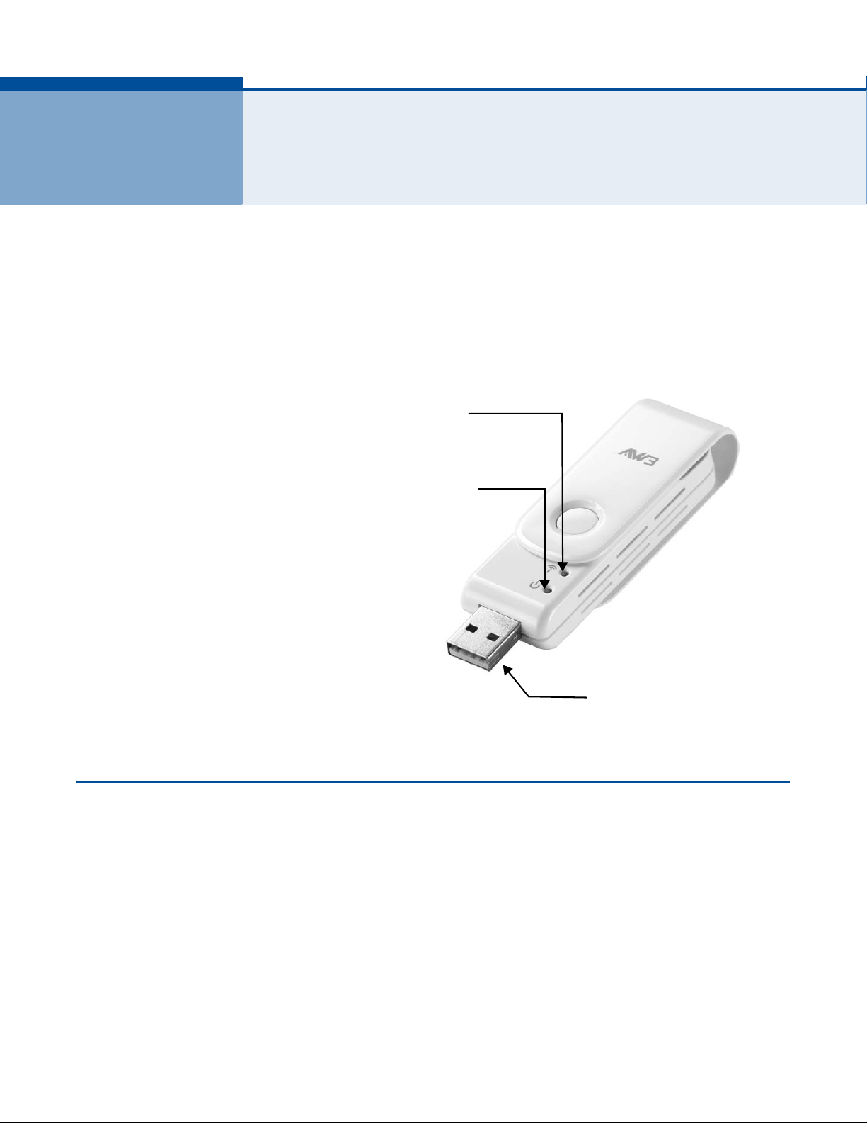
LINK/ACTIVITY LED Indicator
POWER LED Indicator
USB Connector
The WiMAX USB Adapter is a network adapter that enables a notebook PC
to connect to a service provider’s 3.8 GHz mobile WiMAX network.
The USB adapter plugs directly into a PC’s compatible USB port and
includes its own driver and configuration software for Windows XP,
Windows Vista, and Windows 7.
Figure 1: WiMAX USB Adapter
FEATURES
The WiMAX USB Adapter supports the following features:
◆ Mobile WiMAX IEEE 802.16e-2005 Wave 2 compliant
◆ Full Non-Line-of-Sight (NLOS) operation
◆ Two LED indicators for power and link status
◆ Easy installation with a user-f riendly interface for configuration.
◆ Driver support for Windows XP with Service Pack 2 (SP2), Windows
Vista, and Windows 7
– 9 –
Page 10

SYSTEM REQUIREMENTS
Before you install the WiMAX USB Ad apter, check your system meets the
following requirements:
◆ A notebook or desktop computer with a USB port
◆ Microsoft Windows XP, Windows Vista or Windows 7
◆ A 1 GHz Pentium CPU or higher with a minimum of 256 MB of RAM
PACKAGE CHECKLIST
The WiMAX USB Adapter package includes these items:
◆ WiMAX USB Adapter (US330)
C
HAPTER
1
| Introduction
System Requirements
◆ Quick Installation Guide
Inform your dealer if there are any incorrect, missing or damaged items. If
possible, retain the carton, including the original packing materials. Use
them to repack the product in case there is a need to return it.
HARDWARE DESCRIPTION
The US330 WiMAX USB Adapter enables notebook PC users to connect to a
WiMAX Internet access service provider.
USB CONNECTOR The USB adapter can be installed in any notebook PC with a USB port. The
notebook PC must be running Windows XP with Service Pack 2, Windows
Vista, or Windows 7.
– 10 –
Page 11
C
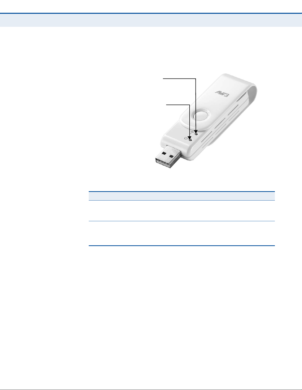
LINK/ACTIVITY LED Indicator
POWER LED Indicator
HAPTER
1
| Introduction
Hardware Description
LED INDICATORS The WiMAX USB Adapter includes two status LED indicators, as described
in the following figure and table.
Figure 2: LED Indicators
Table 1: LED Indicators
LED Status Description
Power On Orange The USB adapter is correctly installed in a USB port
Blinking The adapter is trying to connect to a base statio n.
Link/Activity On Green The USB adapter is searching for a WiMAX base
Blinking The USB adapter has an established link with a base
and is receiving power.
station.
station and is transmitting or receiving data.
– 11 –
Page 12
2 INSTALLATION
To install the WiMAX USB Adapter driver and software utility for Windows
XP or WIndows Vista, follow these steps:
N
OTE
:
Only the installation interface for Windows XP is shown in this guide.
However, the utility installation screens are similar for all Microsoft
Windows systems.
1. Turn on your notebook and wait until the Windows system has
completely started.
2. Insert the adapter into an available USB port. When the USB adapter is
inserted correctly, its blue LED turns on (see page 10).
3. The setup wizard program should start automatically. If the install
program does not start automatically, use Windows Explorer to find the
USB adapter, which appears as an external USB drive. Open the folder
and find the file “Setup.exe” to start the install program.
N
OTE
:
If you encounter problems installing the USB adapter, see
“Troubleshooting” on page 24.
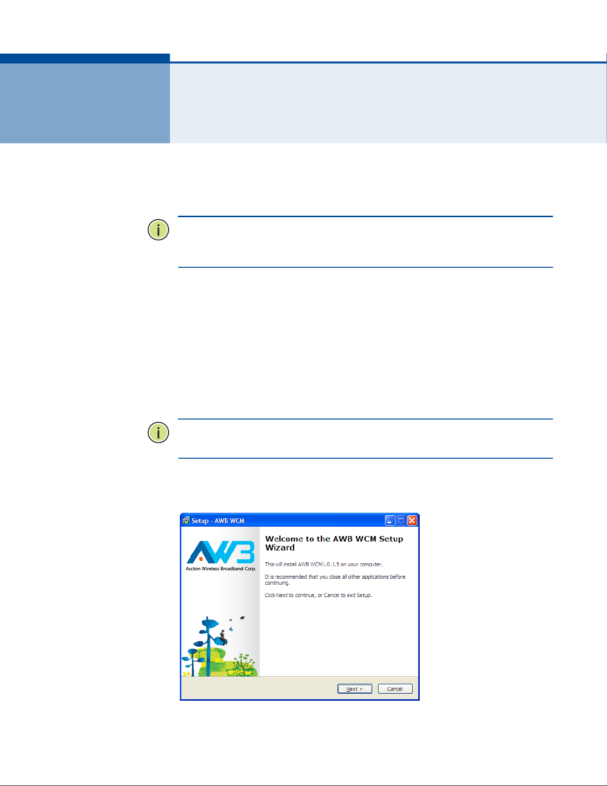
4. Click Next to continue the installation.
Figure 3: Setup Wizard Start
– 12 –
Page 13

C
HAPTER
2
| Installation
5. Select to accept the license agreement terms, then click Next.
Figure 4: Accept License Agreement Terms
6. Confirm or change the location of the installation files on the PC before
clicking Next.
Figure 5: Confirm Installation Location
– 13 –
Page 14

C
HAPTER
7. Confirm to create a desktop icon before clicking Next.
Figure 6: Create Desktop Icon
2
| Installation
8. Check selected options before clicking Install.
Figure 7: Ready to Install Files
– 14 –
Page 15

C
HAPTER
9. Wait for the software installation procedure to complete.
Figure 8: Installation in Progress
2
| Installation
N
OTE
:
If a message concerning Windows Logo testing is display ed, click the
“Continue Anyway” button.
N
OTE
:
If you are prompted to install the Microsoft Visual C++ 2005
Redistributable Package on your system click “Yes” and follow the
instructions.
10. When the “Setup Wizard Complete” message displays, click Finish.
Figure 9: Setup Wizard Complete
– 15 –
Page 16

C
C
AUTION
HAPTER
:
Safely remove the USB adapter by double-clicking the Safely
2
| Installation
Remove Hardware icon in the notification area. Click the device and
then click Stop.
– 16 –
Page 17

3 CONFIGURATION
Double click the icon to
start the utility
Double click the icon to
open the application window.
Click the right mouse button
to open a menu of configuration
The WiMAX Connection Manager (WCM) software provides all the tools to
manage and monitor your WiMAX connection. After initial installation, the
software starts automatically every time you insert the WiMAX USB
Adapter.
ACCESSING THE WCM UTILITY
Once the utility installation is complete, there are several methods of
starting the WCM software other than by inserting the WiMAX USB Adapter.
The utility screens are similar for all Microsoft Windows systems. The
interface for Windows XP is described in this user guide.
From the WCM shortcut icon on the Windows XP or Windows Vista desktop:
Figure 10: WCM Desktop Icon
From the WCM icon on the Windows System Tray:
Figure 11: WCM System Tray Icon
The System Tray icon also indicates the WiMAX connection status.
No connection to a WiMAX network.
Connected to network with an assigned IP address. The yellow
color bars indicate the receive signal level.
– 17 –
Page 18

CONNECTION MANAGEMENT
The WCM login screen displays inf o rm a t ion about the wireless link to the
service provider network.
Figure 12: Login Screen - Auto login
C
HAPTER
3
| Configuration
Connection Management
Auto login — Enter the “Account” and “Password” provided for your log in
to the WiMAX service, then click the Connect button. Next time the WCM
utility launches, it automatically logs in using the account details previously
entered.
Remember my login data — If selected, the WCM utility saves the
account name only when the Connect button is clicked. Next time the WCM
utility is launched, the Account field retains the previous log-in information.
Remember my password — If selected, the WCM utility saves the
account name and password when the Connect button is clicked. You will
not need to sign in the next time the WCM utility is launched.
– 18 –
Page 19

C
HAPTER
3
| Configuration
Connection Management
Once connected to a WiMAX network, the WCM screen displays information
about the wireless link to the service provider network.
Figure 13: Connection Status
The displayed items on this screen can be described as follows:
Provider — The service provider name to which the adapter is connected.
IP Address — The IP address assigned to the adapter.
Subnet Mask — Indicates the local subnet mask, such as 255.255.255.0.
Default Gateway — The gateway address provided by the WiMAX service
provider.
DNS Server — Address of the DNS server, specified in the form of 0.0.0.0.
– 19 –
Page 20

ADAPTER SETTINGS
C
HAPTER
3
| Configuration
Adapter Settings
The Setting screen enables specific adapter and WCM utility features to be
configured.
Figure 14: Settings Screen
The displayed items on this screen can be described as follows:
Auto-run WiMAX Connection Manager — Automatically starts the WCM
utility when the adapter is inserted into a PC slot.
Run WiMAX Connection Manager as minimum size — When set to
automatically start WCM, the utility starts in its Windows minimized form.
Automatically update — Automatically check for available WCM software
updates.
Enable Debug Monitor — Enables logging of messages to the WCM
debug monitor. The debug monitor window is displayed when the WCM
utility restarts.
Figure 15: Debug Monitor Window
– 20 –
Page 21

WIMAX CONNECTION STATISTICS
The Statistics screen allows you to view information on the WiMAX
connection.
Figure 16: Statistics Information
C
HAPTER
WiMAX Connection Statistics
3
| Configuration
The displayed items on this screen can be described as follows:
BSID — The current base station ID to which the mobile station is
currently connected.
Online Duration — The time the unit has had a link with the base station
for the current session.
DL Data Volume — The downloaded data volume in Mbytes for the
current online session.
UL Data Volume — The uploaded data volume in Mbytes for the current
online session.
DL Data Rate — The current download data rate in Kbps.
UL Data Rate — The current upload data rate in Kbps.
CINR — The current carrier-to-interference-plus-noise ratio of the
received WiMAX radio signal.
RSSI — The current receive signal strength indicator value of the received
WiMAX radio signal.
Transmit Power — The current transmit power of the WiMAX radio signal.
– 21 –
Page 22

ABOUT WIMAX CONNECTION MANAGER
The About page displays information about the software version the WCM
utility.
Figure 17: About WCM Information
C
HAPTER
About WiMAX Connection Manager
3
| Configuration
– 22 –
Page 23

4 ADMINISTRATOR MODE
The WiMAX USB Adapter has an Administrator Mode fo r configuring profiles
and accessing the Advanced Configuration settings.
Administrator Mode is intended for qualified service personnel only.
ACCESSING ADMINISTRATOR MODE
Administrator Mode is accessed through the key sequence “Alt + t,” which
prompts for a password.
The password for Administrator Mode is “wimax123” (case sensitive).
Figure 18: WCM Change Mode
Once in Administrator Mode, the user can create, edit, and delete profiles,
configure authentication settings, and access the Advance Configur ation
screen.
Using the key sequence “Alt + t” a second time exits Administrator Mode.
– 23 –
Page 24

Figure 19: Administrator mode - Auto login
C
HAPTER
4
| Administrator Mode
Editing a Profile
EDITING A PROFILE
Double-click the system tray icon to open the application window. Then
right-click on the icon to open the configuration menu.
From the configuration menu, select “Profile.”
Figure 20: Profile Icon
– 24 –
Page 25

C
HAPTER
4
| Administrator Mode
Editing a Profile
Clicking the Scan tab on the Profile screen displays the profile frequency
and bandwidth settings.
Figure 21: Profile Screen - Scan Tab
The Scan tab on the Edit Profile screen displays the following items:
◆ Frequency — Specifies a center frequency to scan.
◆ Bandwidth — Specifies the bandwidth of the channel; 5 or 10 MHz.
– 25 –
Page 26

C
HAPTER
4
| Administrator Mode
Editing a Profile
Clicking the Authentication tab on the Profile screen displays the user
authentication settings.
Figure 22: Profile Screen - Authentication
EAP Method — Selects the Extensible Authentication Protocol (EAP)
method to use for authentication. When EAP-TTLS or EAP-TLS is selected,
the appropriate parameters need to be configured.
◆ EAP-TTLS-MS-CHAP-V2 — Tunneled Transport Layer Security with
Microsoft’s version 2 of CHAP (Challenge-Handshake Authentication
Protocol). This security method provides for certificate-based, mutual
authentication of the client and network through an encrypted channel.
Unlike EAP-TLS, EAP-TTLS requires only server-side certificates. The
MS-CHAP protocol requires a user name and password to be
configured. The user name and password can be up to 50 characters.
(The following characters are not permitted; /\|”?@#$%^&*():;<>,. )
◆ EAP-TLS — T ransport Lay er Security . Provides for certificate-based and
mutual authentication of the client and the network. It relies on clientside and server-side certificates to perform authentication and can be
used to dynamically generate user-based and session-based encryption
keys to secure subsequent communications between the user and the
network.
Outer NAI —The Network Access Identifier (NAI) text string that is used
to identify the home authentication realm for device authentication during
roaming. The NAI string (defined in RFC 4282) is used to proxy an
authentication request to another remote server. The authentication is then
performed using the unique X.509 authentication certificate included with
the device. The string can be defined by three methods:
– 26 –
Page 27

C
HAPTER
4
| Administrator Mode
Editing a Profile
◆ MAC: Uses the device MAC address as part of the identity.
◆ RANDOM: Uses a generated random number of 26 hexadecimal digits.
◆ CUSTOMIZE: Allows the whole string to be defined as required.
Trust CA Certificate — The security certificate issued by a recognized
certification authority (CA) that is used for mutual authentication with the
authentication server when EAP-TLS is used. The browse button can be
used to locate the file on the host PC.
User name — A text string used by EAP-TTLS-MS-CHAP-V2 to identify the
user to the authentication server.
Password — The password used by EAP-TTLS-MS-CHAP-V2 to confirm the
identity of the user to the authentication server.
– 27 –
Page 28

A TROUBLESHOOTING
DIAGNOSING LED INDICATORS
Table 2: LED Indicators
LED Status Probable Cause Action
Orange LED is Off The USB adapter is
Green LED is Off The USB adapter
not receiving power
cannot detect a
WiMAX base station
◆ Remove the USB adapter and reinsert it in
◆ T ry the USB adapter in another USB port. If
◆ Check the USB adapter and port connectors
◆ Try the USB adapter in another PC’s port
◆ If you cannot resolve the problem, contact
◆ Verify the area covered by your WiMAX
◆ Move to another location within the WiMAX
the slot. Be sure the card is securely seated
in the port.
this also fails, test your PC with another
USB adapter that is known to operate
correctly.
for any physical damage.
that is known to operate correctly.
your local dealer for assistance.
service provider.
service area.
NETWORK CONNECTION PROBLEMS
If you cannot access the Internet from the PC, check the following:
◆ Make sure the WCM software and driver is correctly installed on your
system. If necessary, try uninstalling and reinstalling the software.
◆ If you cannot access the Internet, be s ure your Windows system is
correctly configured for TCP/IP. The IP settings should be set to “obtain
an IP address automatically.”
◆ You may have moved out of the service area of the WiMAX network.
The WCM main screen should indicate that there is no connection. Call
the service provider for service coverage information.
◆ The service provider’s profile may not be configured correctly. Check
that the Authentication Mode settings are correct.
– 28 –
Page 29

◆ If you cannot resolve the problem, check the error logs from the WCM
WCM unistall option on the
Window Start menu
Status screen and contact your service provider.
UNINSTALLING THE WCM SOFTWARE
If you are having problems with the WiMAX USB Adapter or the WCM
software, you may need to uninstall the USB adapter driver and software
from the Windows system.
Follow these steps:
1. From the Windows Start menu, go to the WCM software entry.
2. Click the Uninstall WCM option on the menu.
Figure 23: Uninstall WCM
A
PPENDIX
Uninstalling the WCM Software
A
| Troubleshooting
3. Click the Yes button to confirm the uninstall process.
Figure 24: Confirm Uninstall
4. When the uninstall is complete, click OK to exit.
Figure 25: Uninstall Complete
– 29 –
Page 30

B SPECIFICATIONS
HOST INTERFACE USB 2.0 specification
STANDARD COMPLIANT IEEE 802.16e-2005 Wave 2
AIR INTERFACE Scaleable OFDMA
DUPLEX MODE TDD/5ms frame
ANTENNA Printed antenna
Transmit: Two antennas
Receive: Two antennas
Gain: 2 dBi
Pattern: Omnidirectional
Impedance: 50 ohms
POWER CONSUMPTION 2.4 W maximum
PHYSICAL SIZE 25 x 89 x 16 mm (0.98 x 3.50 x 0.62 in.)
WEIGHT 23 g (0.81 oz)
OPERATING FREQUENCY
Frequency Band CE FCC
3.8G 3300-3800 3650-3675
BANDWIDTH
ALLOCATION
Bandwidth Allocation 5 MHz
3.8G
10 MHz
– 30 –
Page 31

MODULATION SCHEME PRBS subcarrier randomization
Contains pilot, preamble, and ranging modulation
A
PPENDIX
B
| Specifications
MODULATION AND
CODING TYPES
Down Link
QPSK 1/2 CTC
QPSK 3/4 CTC
16 QAM 1/2 CTC
16 QAM 3/4 CTC
64 QAM 1/2 CTC
64 QAM 2/3 CTC
64 QAM 3/4 CTC
64 QAM 5/6 CTC
Up Link
QPSK 1/2 CTC
QPSK 3/4 CTC
16 QAM 1/2 CTC
16 QAM 3/4 CTC
MAXIMUM THROUGHPUT Downlink Peak Rate: > 20 Mbps
Uplink Peak Rate: > 7 Mbps
TRANSMIT POWER Maximum Power class less than +23 dBm
RECEIVE SENSITIVITY QPSK 1/2 CTC: -94 dBm
16-QAM 3/4 CTC: -82 dBm
64-QAM 3/4 CTC: -76 dBm
SECURITY/ENCRYPTION PKMv2 with 128 bit AES/CCM, EAP-TLS, EAP-TTLS
QOS MECHANISM Dynamic Service Flow Creation, Change, Deletion
Scheduling: UGS, RT-VR, NRT-VR, ERT-VR and BE
OPERATING
Operating: -5 °C to 45 °C (32 to 113 °F)
TEMPERATURE
HUMIDITY Operation: 5% to 95% (non-condensing)
Maximum Storage: 95%
– 31 –
Page 32

A
PPENDIX
B
| Specifications
EMMISSIONS/IMMUNITY
COMPLIANCE
FCC 47 CFR Part 15 Class B
EN 301 489-1/-17
SAFETY EN60950-1
RADIO SIGNAL
CERTIFICATION
SPECIFIC ABSORPTION
RATE (SAR)
US: 3.8 GHz - CFR 47 Part 90Z
Europe (3.5GHz): EN 302 623
US: FCC OET Bulletin 65, Supplement C
Europe: EN62311
SOFTWARE DRIVERS Windows XP SP2,Windows Vista and Windows 7
NDIS 5.0 PnP ETH 802.3 device driver specification
WHQL certified
LED Status Description
Power On Orange The USB adapter is correctly installed in a USB
Blinking The adapter is trying to connect to a base station.
port and is receiving power.
Link/Activity On Green The USB adapter is searching for a WiMAX base
Blinking The USB adapter has an established link with a
station.
base station and is transmitting or receiving data.
– 32 –
Page 33

GLOSSARY
AUTHENTICATION The process to verify the identity of a subscriber requesting network
access.
BANDWIDTH The difference between the highest and lowest frequencies available for
network signals. Also synonymous with network speed, the actual speed of
data transmission through a medium.
BASE STATION A WIMAX service provider’s equipment that is installed at a fixed location
to provide network connectivity for subscriber stations within a defined
service area.
CINR Carrier-to-Interference-Plus-Noise-Ration: A measurement of the channel
quality in a WiMAX link. Subscri ber stations measure the receive d CIN R
and send the information back to the base station. The base station can
then adjust modulation and coding for the link to optimize throughput.
CENTER FREQUENCY The radio frequency at the center of a WiMAX channel. WiMAX channels
can be of different widths (the channel bandwidth) and the transmitted
radio signal is spread across the full width of the channel.
CHANNEL BANDWIDTH The range of frequencies occupied by a WiMAX r adio signal. The amount of
information that can be transmitted in a r a dio signal is related to the
channel bandwidth, which is measured in Megahertz (MHz). WiMAX
supports a range of channel bandwidths that can be defined by the service
operator depending on performance requirements, operating preferences,
and regulatory constraints.
CPE Customer-Premises Equipment: Terminal equipment provided by a service
provider that is located at a subscriber’s premises and supports a
communication channel between a customer and the service provider.
CPU Central Processing Unit: The CPU, or processor, is the part of a computer
where most calculations take place. In most of today’s PCs, the CPU is
contained on a single chip. The type and speed (in GHz) of a CPU largely
defines the processing power of a computer.
– 33 –
Page 34

G
LOSSARY
DNS Domain Name System: A system used for translating host names for
network nodes into IP addresses.
DHCP Dynamic Host Configuration Protocol: Provides a framework for passing
configuration information to hosts on a TCP/IP network. DHCP is based on
the Bootstrap Protocol (BOOTP), adding the capability of automatic
allocation of reusable network addresses and additional configuration
options.
ENCRYPTION Data passing between a base station and subscribers uses encryption to
protect from interception and evesdropping.
EAP Extensible Authentication Protocol: An authentication protocol used to
authenticate subscribers. EAP is used with TLS or TTLS authenticati on to
provide “mutual authenticati on ” be tween a subscriber and a WiMAX
network.
IEEE 802.16E The WiMAX standard that provides mobile broadband wireless access using
Scalable Orthogonal Frequency Division Multiple Access (SOFDMA).
INTERNET SERVICE
PROVIDER
A company that offers an access service that connects customers to the
Internet.
IP ADDRESS The Internet Protocol (IP) address is a numerical identification assigned to
a device that communicates in a network using the Internet Protocol.
LED Light Emitting Diode: Used for indicating a device or network condition.
LAN Local Area Network: A group of interconnected computers and support
devices.
MAC ADDRESS The physical layer address used to uniquely i den tify network nodes.
MS-CHAPV2 Microsoft’s version 2 of the Challenge-Handshake Authentication Protocol.
Introduced by Microsoft with Windows 2000, MS-CHAPV2 (defined in RFC
2759) provides mutual authentication between peers using user names
and passwords.
NETWORK ADAPTER A hardware device that enables a computer to communicate over a
network. The adapter provides physical access to a particular networking
medium.
– 34 –
Page 35

G
LOSSARY
RAM Random Access Memory: The memory in a computer where the operating
system, application programs, and other data currently in use are stored.
RAM is volatile memory where data is lost when the computer is turned off.
Having more RAM in a computer reduces the time the processor takes to
read data, which increases overall computer performance.
RSSI Receive Signal Strength Indicator: A measurement of the strength of a
received wireless signal. The higher the RSSI value, the stronger the
received signal from the antenna.
ROAMING The process where a WiMAX subscriber can move onto another operator’s
network while maintaining a continuous connection.
SOFDMA Scalable Orthogonal Frequency Division Multiple Access: The air interface
defined for mobile WiMAX. SOFDMA is a multiple access method that allows
simultaneous transmissions to and from several users, employing a
subchannel structure that scales with bandwidth.
SERVICE PROVIDER See Internet Service Provider.
SIM Subscriber Identity Module: A standard for a small removable integrated
circuit card that securely stores information used to identify a mobile
wireless subscriber.
SUBSCRIBER STATION A general term for a customer’s terminal equipment that provides
connectivity with a WIMAX network.
TCP/IP Transmission Control Protocol/Interne t Pr otocol: Protocol suite that
includes TCP as the primary transport protoc ol, and IP as the network layer
protocol.
TLS Transport Layer Security: An standard defined in RFC 5216, EAP-TLS is an
authentication protocol that provides strong security through the use of
client-side certificates.
TTLS Tunneled Transport Layer Security: EAP-TTLS is a protocol extension of
EAP-TLS. The authentication server is authenticated to the client using its
Certification Authority certificate, this establishes a secure “tunnel”
through which the client is then authenticated.
USIM Universal Subscriber Identity Module: See Subscriber Identity Module.
– 35 –
Page 36

G
LOSSARY
URL Uniform Resource Locator: An easy-to-read char acter string that is used t o
represent a resource available on the Internet. For example, “http://
www.url-example.com/.”
WIMAX The IEEE 802.16 standard for Worldwide Interoperability for Microwave
Access. The IEEE 802.16-2004 standard, known as “fixed WiMAX,”
supports only point-to-point links and has no support for mobility. The IEEE
802.16e-2005 standard, known as “mobile WiMAX,” is an amendment to
IEEE 802.16-2004 and supports mobility . Note that mobile WiMAX standard
is not backward compatible with the fixed WiMAX standard.
– 36 –
Page 37

INDEX
A
About page 22
account login 18
auto login 18
Automatically update 20
auto-run WCM 20
B
BSID 21
C
CINR 21
connection manager 17
connection status icons 17
D
data rates 21
data volume 21
Debug Monitor, enabling 20
DNS server 19
download rate 21
E
EAP methods 26
G
gateway address 19
N
name server 19
netmask, IP 19
O
online duration 21
P
package checklist 10
password, remember 18
R
remember login data 18
RSSI 21
S
service provider link 19
service provider login 18
service provider name 19
session duration 21
shortcut icon, WCM 17
signal level icon 17
software information 22
software updates 20
specifications 30
statistics, connection 21
status icons 17
subnet mask 19
I
icons, connection status 17
ID of base station 21
introduction 9
IP Address 19
L
LED indicators 11
logging messages 20
M
management utility 17
minimized form, WCM 20
T
tools, management 17
transmit power 21
troubleshooting 28
U
updates, automatic 20
upload rate 21
V
volume of data 21
– 37 –
Page 38

W
WCM
auto-run 20
debug monitor 20
information 22
log 20
login 18
minimized form 20
password 18
shortcut 17
starting 17
statistics 21
system tray icon 17
wireless link 19
WCM Utility 17
WiMAX link 19
I
NDEX
– 38 –
Page 39

US330
E082012-AP-R03
150200000248W
 Loading...