

Page 1

Þ¿®®·½¿¼»ÌÓ Ò
Ü®¿º¬ ïï² É·®»´»-- Þ®±¿¼¾¿²¼ ᫬»®
НУЭЙЮОпмНуТн
Page 2

Page 3

Draft 11n Wireless Broadband Router
User Guide
20 Mason
Irvine, CA 92618
Phone: (949) 679-8000
Pub. # 149100000009W
June 2009
E062009-AP-R01
Page 4

Information furnished by SMC Networks, Inc. (SMC) is believed to be accurate and
reliable. However, no responsibility is assumed by SMC for its use, nor for any
infringements of patents or other rights of third parties which may result from its use. No
license is granted by implication or otherwise under any patent or patent rights of SMC.
SMC reserves the right to change specifications at any time without notice.
Copyright © 2009 by
SMC Networks, Inc.
20 Mason
Irvine, CA 92618
All rights reserved.
Trademarks:
SMC is a registered trademark; and EZ Switch, TigerStack and TigerSwitch are
trademarks of SMC Networks, Inc. Other product and company names are trademarks or
registered trademarks of their respective holders.
Page 5

Warranty and Product Registration
To register SMC products and to review the detailed warranty statement, please refer to
the Support Section of the SMC Website at http://www.smc.com.
i
Page 6

Compliances
Federal Communication Commission Interference Statement
This equipment has been tested and found to comply with the limits for a Class B digital
device, pursuant to Part 15 of the FCC Rules. These limits are designed to provide
reasonable protection against harmful interference in a residential installation. This
equipment generates, uses and can radiate radio frequency energy and, if not installed
and used in accordance with the instructions, may cause harmful interference to radio
communications. However, there is no guarantee that interference will not occur in a
particular installation. If this equipment does cause harmful interference to radio or
television reception, which can be determined by turning the equipment off and on, the
user is encouraged to try to correct the interference by one of the following measures:
Reorient or relocate the receiving antenna
Increase the separation between the equipment and receiver
Connect the equipment into an outlet on a circuit different from that to which the receiver
is connected
Consult the dealer or an experienced radio/TV technician for help
This device complies with Part 15 of the FCC Rules. Operation is subject to the following
two conditions: (1) This device may not cause harmful interference, and (2) this device
must accept any interference received, including interference that may cause undesired
operation.
FCC Caution: Any changes or modifications not expressly approved by the party
responsible for compliance could void the user's authority to operate this equipment.
IMPORTANT NOTE:
FCC Radiation Exposure Statement
This equipment complies with FCC radiation exposure limits set forth for an uncontrolled
environment. This equipment should be installed and operated with minimum distance
20cm between the radiator and your body. End users must follow the specific operating
instructions for satisfying RF exposure compliance.
This transmitter must not be co-located or operating in conjunction with any other antenna
or transmitter.
IEEE 802.11b, 802.11g or 802.11n operation of this product in the U.S.A. is
firmware-limited to channels 1 through 11.
The availability of some specific channels and/or operational frequency bands are country
dependent and are firmware programmed at the factory to match the intended
destination. The firmware setting is not accessible by the end user.
ii
Page 7

EC Conformance Declaration
Marking by the above symbol indicates compliance with the Essential Requirements of
the R&TTE Directive of the European Union (1999/5/EC). This equipment meets the
following conformance standards:
EN 60950-1: 2006
Safety of Information Technology Equipment
EN 50385: 2002
Generic standard to demonstrate the compliance of electronic and electrical apparatus
with the basic restrictions related to human exposure to electromagnetic fields (0 Hz 300 GHz)
EN 300328 V1.7.1 (2006)
Electromagnetic compatibility and Radio spectrum Matters (ERM); Wideband
transmission systems; Data transmission equipment operating in the 2,4 GHz ISM
band and using wide band modulation techniques; Harmonized EN covering essential
requirements under article 3.2 of the R&TTE Directive
EN 301 489-1 V1.8.1 (2008-04) and EN 301 489-17 V1.3.2 (2008-4)
Electromagnetic compatibility and Radio spectrum Matters (ERM); ElectroMagnetic
Compatibility (EMC) standard for radio equipment and services; Part 17: Specific
conditions for 2,4 GHz wideband transmission systems and 5 GHz high performance
RLAN equipment
This device is a 2.4 GHz wideband transmission system (transceiver), intended for use in
all EU member states and EFTA countries, except in France and Italy where restrictive
use applies.
In Italy the end-user should apply for a license at the national spectrum authorities in
order to obtain authorization to use the device for setting up outdoor radio links and/or for
supplying public access to telecommunications and/or network services.
This device may not be used for setting up outdoor radio links in France and in some
areas the RF output power may be limited to 10 mW EIRP in the frequency range of 2454
- 2483.5 MHz. For detailed information the end-user should contact the national spectrum
authority in France.
This device is intended for use in the following European Community and EFTA countries:
Czech
Estonian
Eesti
EnglishHereby, SMC, declares that this Radio LAN device is in compliance
Käesolevaga kinnitab SMC seadme Radio LAN device vastavust
direktiivi 1999/5/EÜ põhinõuetele ja nimetatud direktiivist tulenevatele
teistele asjakohastele sätetele.
with the essential requirements and other relevant provisions of
Directive 1999/5/EC.
iii
Page 8
Finnish
Suomi
Dutch
Nederlands
French
Français
Swedish
Svenska
Danish
Dansk
German
Deutsch
Greek smc radio LAN device
Hungarian
Magyar
Italian
Italiano
Latvian
Latviski
SMC vakuuttaa täten että Radio LAN device tyyppinen laite on
direktiivin 1999/5/EY oleellisten vaatimusten ja sitä koskevien
direktiivin muiden ehtojen mukainen.
Hierbij verklaart SMC dat het toestel Radio LAN device in
overeenstemming is met de essentiële eisen en de andere relevante
bepalingen van richtlijn 1999/5/EG
Par la présente SMC déclare que l'appareil Radio LAN device est
conforme aux exigences essentielles et aux autres dispositions
pertinentes de la directive 1999/5/CE
Härmed intygar SMC att denna Radio LAN device står I
överensstämmelse med de väsentliga egenskapskrav och övriga
relevanta bestämmelser som framgår av direktiv 1999/5/EG.
Undertegnede SMC erklærer herved, at følgende udstyr Radio LAN
device overholder de væ sentlige krav og øvrige relevante krav i direktiv
1999/5/EF
Hiermit erklärt SMC, dass sich dieser/diese/dieses Radio LAN device
in Übereinstimmung mit den grundlegenden Anforderungen und den
anderen relevanten Vorschriften der Richtlinie 1999/5/EG befindet".
(BMWi)
1999/5/
Alulírott, SMC nyilatkozom, hogy a Radio LAN device megfelel a
vonatkozó alapvetõ követelményeknek és az 1999/5/EC irányelv
egyéb elõírásainak.
Con la presente SMC dichiara che questo Radio LAN device è
conforme ai requisiti essenziali ed alle altre disposizioni pertinenti
stabilite dalla direttiva 1999/5/CE.
Lithuanian
Maltese
Malti
Spanish
Español
iv
Por medio de la presente SMC declara que el Radio LAN device
cumple con los requisitos esenciales y cualesquiera otras
disposiciones aplicables o exigibles de la Directiva 1999/5/CE
Page 9
Polish
Polski
Portuguese
Português
Slovak
Slovensky
Slovenian
Slovensko
SMC declara que este Radio LAN device está conforme com os
requisitos essenciais e outras disposições da Directiva 1999/5/CE.
NCC Statement
v
Page 10

About This Guide
Purpose
This guide details the hardware features of the wireless AP/Router, including its physical
and performance-related characteristics, and how to install the device and use its
configuration software.
Audience
This guide is for PC users with a working knowledge of computers. You should be familiar
with Windows operating system concepts.
Conventions
The following conventions are used throughout this guide to show information:
Note: Emphasizes important information or calls your attention to related features or
instructions.
Caution: Alerts you to a potential hazard that could cause loss of data, or damage the
Warning: Alerts you to a potential hazard that could cause personal injury.
Related Publications
The following publication gives basic information on how to install and use the wireless
AP/Router.
Quick Installation Guide
Also, as part of the wireless AP/Router s software, there is online help that describes all
configuration related features.
system or equipment.
Revision History
This section summarizes the changes in each revision of this guide.
June 2009 Revision
This is the first revision of this guide. This guide is valid for software release v1.0.0.13.
vi
Page 11

Table of Contents
Chapter 1: Introduction 1-1
Package Checklist 1-1
Hardware Description 1-2
Antennas 1-2
LED Indicators 1-3
Ethernet RJ-45 Ports 1-4
Power Socket 1-4
Reset Button 1-4
WPS Button 1-4
Hardware Installation 1-5
Chapter 2: Installation 2-1
Gateway Mode 2-1
Bridge Mode 2-2
Chapter 3: Network Planning 3-1
Internet Gateway Router 3-1
LAN Access Point 3-2
Wireless Bridge 3-3
Chapter 4: Initial Configuration 4-1
Using the Setup Wizard 4-2
DHCP 4-4
Static IP 4-5
PPPoE 4-6
L2TP 4-7
PPTP 4-8
Chapter 5: System Configuration 5-1
Operation Mode configuration 5-4
Internet Settings 5-5
WAN Setting 5-5
DHCP 5-5
Static IP 5-6
PPPoE 5-7
vii
Page 12

Contents
L2TP 5-9
PPTP 5-11
LAN Setting 5-13
Advanced Routing 5-15
QoS Setting 5-17
ALG 5-18
Wireless Settings 5-19
Basic Settings 5-20
Advanced Wireless Settings 5-25
WLAN Security 5-30
Wi-Fi Protected Setup (WPS) 5-37
Station List 5-39
Firewall 5-40
MAC/IP/Port Filtering 5-40
Virtual Server Settings (Port Forwarding) 5-42
DMZ 5-43
System Security 5-44
Content Filtering 5-45
Administration Settings 5-46
System Management 5-46
Upgrade Firmware 5-49
Configuration Settings 5-50
System Status 5-50
Statistics 5-52
DHCP Clients 5-53
System Log 5-54
Reboot 5-54
Appendix A: Troubleshooting A-1
Appendix B: Specifications B-1
Appendix C: License Information C-1
The GNU General Public License C-1
Glossary
Index
viii
Page 13

Chapter 1: Introduction
The SMCWBR14S-N3 wireless AP/Router is an IEEE 802.11n wireless gateway
router that connects your Internet access device (cable or ADSL modem) to your PC
or local area network, or to its own secure wireless network.
The wireless AP/Router can be automatically configured with other Wi-Fi Protected
Setup (WPS) devices by simply pressing its WPS button. For more detailed
configuration, the unit can also be set up through its easy-to-use web interface.
Package Checklist
The wireless AP/Router package includes:
! 802.11b/g/n wireless AP/Router (SMCWBR14S-N3)
! RJ-45 Category 5 network cable
! AC power adapter
! Quick Installation Guide
! User Guide CD
Inform your dealer if there are any incorrect, missing or damaged parts. If possible,
retain the carton, including the original packing materials. Use them again to repack
the product in case there is a need to return it.
1-1
Page 14
Introduction
1
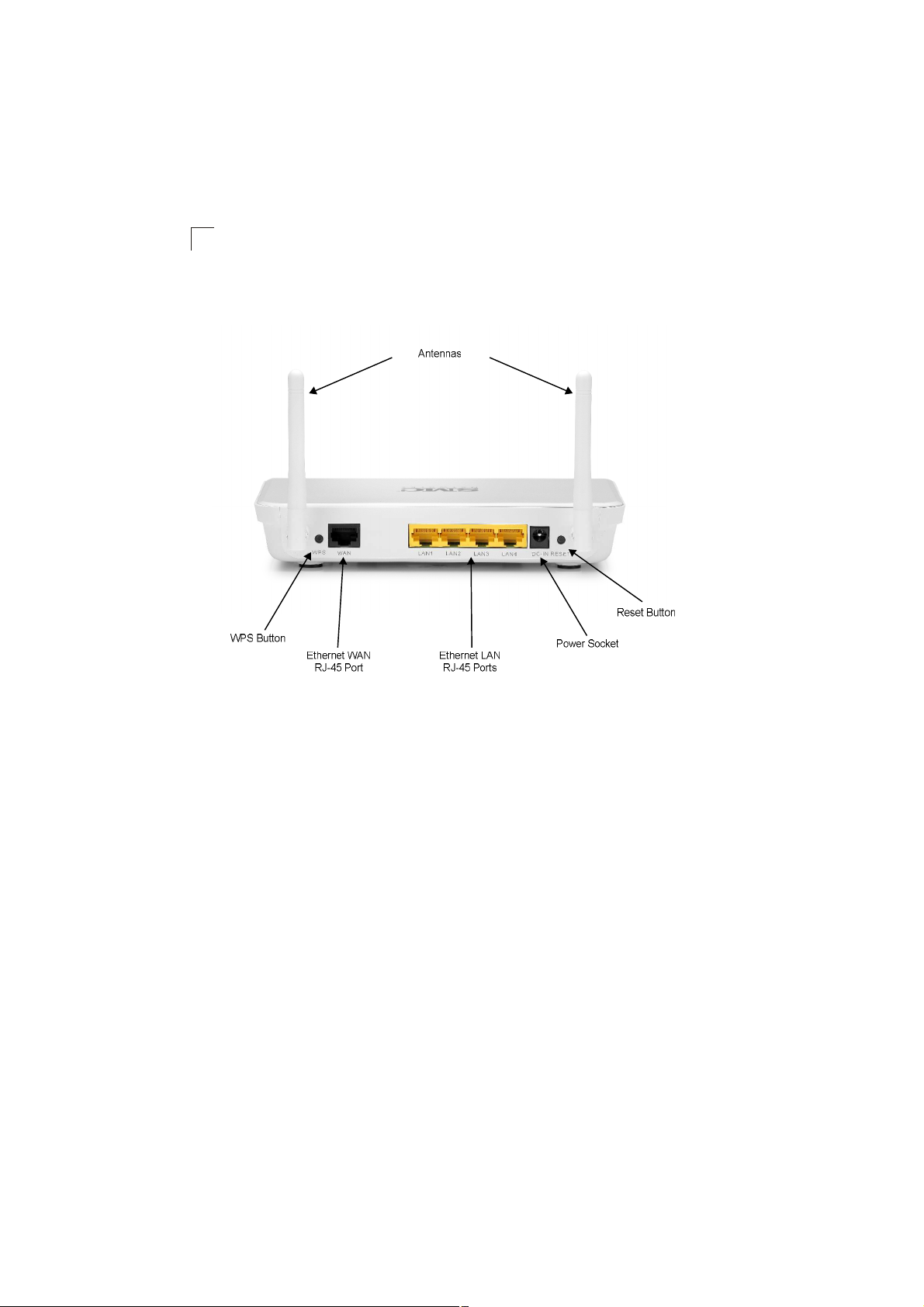
Hardware Description
Figure1-1. Rear Panel
Antennas
The access point includes integrated MIMO antennas for wireless communications.
A MIMO antenna system uses two or more identical antennas to receive and
transmit signals, helping to increase data throughput and range. The antennas
transmit the outgoing signal as a toroidal sphere (doughnut shaped), with the
coverage extending most in a direction perpendicular to the antenna. The antenna
should be adjusted to an angle that provides the appropriate coverage for the
service area.
1-2
Page 15
Hardware Description
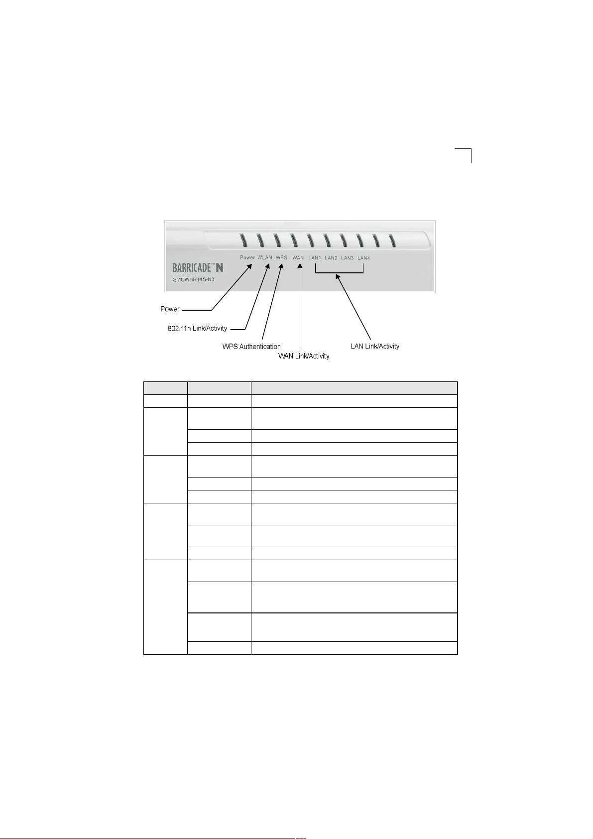
LED Indicators
Thewireless AP/Router includes eight status LED indicators, as described in the
following figure and table.
Figure1-2. LED Indicators
LED Status Description
POWEROn Blue Indicates that the system is working normally.
WANOn Blue Indicates a valid link on the WAN Ethernet port. Flashing indicates
Blinking Blue Indicates the data is being transmitting or receiving.
Off The Ethernet port has no valid link.
LAN (4 LEDs)On Blue Indicates a valid link on the LAN Ethernet port. Flashing indicates
Blinking Blue Indicates the Ethernet port is connected and is transmitting or receiving.
Off The Ethernet port has no valid link.
WLANOn Blue Indicates the 802.11n radio is enabled. Flashing indicates wireless
Blinking Blue Indicates the AP/Router has an established connection and is
Off Indicates the 802.11n radio is disabled.
WPSOn Indicates the WPS authentication of a device has been successfully
Fast Blinking Blue** Indicates the WPS authentication of a client device is in progress.
Slow Blinking Blue* Indicates the WPS authentication of a device did not complete after
Off Indicates that WPS is not in progress.
network activity.
network activity.
network activity.
transmitting and receiving data.
completed.
If the WPS authentication of a device does not complete after 120
seconds, the LED changes to Slow Blinking.
120 seconds. The LED status does not change until the user restarts
or disables the WPS connection.
1
1-3
Page 16

Introduction
1
*Slow blinking is an on-off cycle of once every 2 seconds.
**Fast blinking is an on-off cycle of once of every 0.5 seconds.
Ethernet RJ-45 Ports
Thewireless AP/Router has the following RJ-45 ports:
! The four RJ-45 LAN ports are for connections to PCs or to a 10/100 Mbps network
switch.
! The RJ-45 WAN port is for connection to a DSL or cable modem, or to a LAN or
other device that provides your Internet access.
All RJ-45 ports auto-negotiate the operating speed to 10/100 Mbps, the mode to
half/full duplex, and the pin signals to MDI/MDI-X. Automatic MDI/MDI-X support
enables you to use straight-through cables for all network connections to PCs,
switches, or hubs.
Power Socket
Thewireless AP/Router does not have a power switch. It is powered on when
connected to the AC power adapter, and the power adapter is connected to a power
source. The power adapter automatically adjusts to any voltage between 100-240
volts at 50 or 60 Hz. No voltage range settings are required.
Reset Button
The Reset button can be used to restart the wireless AP/Router or restore the
factory default configuration. If you press the button for less than 5 seconds, the
wireless AP/Router will restart. If you press and hold down the button for 5 seconds
or more, any configuration changes you may have made are removed and the
wireless AP/Router is restored to its factory default configuration.
WPS Button
Use the WPS button on the wireless AP/Router to automatically connect devices to
the network. Within two minutes, press the physical or virtual button on a single
wireless client device to enable it to join the WLAN.
The WPS configuration process may be initiated on any device. Only one client
device can connect with the wireless AP/Router after the WPS button is pressed.
There is no restriction to the order in which buttons are pressed.
Note: Any WPS-compatible devices could unintentionally join the WLAN if they are
within range during the two-minute set up period after the WPS button is pressed.
Note that only one device at a time can join the network when using the WPS
button.
1-4
Page 17

Hardware Installation
Hardware Installation
1. Select a Site Choose a proper place for the wireless AP/Router. In general,
the best location is at the center of your wireless coverage area, within line of
sight of all wireless devices. For optimum performance, consider these points:
! Mount the wireless AP/Router as high as possible above any obstructions in
the coverage area.
! Avoid mounting next to or near building support columns or other
obstructions that may cause reduced signal or null zones in parts of the
coverage area.
! Mount away from any signal absorbing or reflecting structures (such as those
containing metal).
Note: When choosing a site for mounting the router on a wall, consider the accessibility
for network cabling.
2. Mount the Wireless AP/Router The wireless AP/Router can be mounted on
any horizontal surface.
Mounting on a horizontal surface To keep the access point from sliding on
the surface, attach the four rubber feet provided in the accessory kit to the
marked circles on the bottom of the access point.
Mounting on a wall or wood surface The access point should be mounted
only to a wall or wood surface that is at least 1/2-inch plywood or its
equivalent.
! For wall or wood surface mounting, use a cross-head screwdriver and the
20-mm M4 tap screws (not included). Or, drill two holes and insert two hooks.
1
! Mount the access point to the screws or hooks.
Note: Mount the router with the front panel facing upward so that the status LED
indicators are clearly visible.
1-5
Page 18

1
Introduction
1-6
Page 19
Chapter 2: Installation
ݱ²²»½¬ßÝ °±©»®
The wireless AP/Router has two basic operating modes that can be set through the
web-based management interface. For information on setting the mode suitable for
your network environment, see "Operation Mode configuration# on page5-4.
! Gateway Mode $ Normal gateway mode that connects a wired LAN and wireless
clients to an Internet access device, such as a cable or DSL modem. This is the
factory set default mode.
! Bridge Mode $ An access point mode that extends a wired LAN to wireless
clients.
In addition to these basic operating modes, each wireless interface supports a
Wireless Distribution System (WDS) link to another wireless AP/Router. These
advanced configurations are not described in this section. See "Network Planning#
on page 3-1 for more information.
In a basic configuration, how the wireless AP/Router is connected depends on the
operating mode. The following sections describe connections for basic Gateway
Mode and Bridge Mode operation.
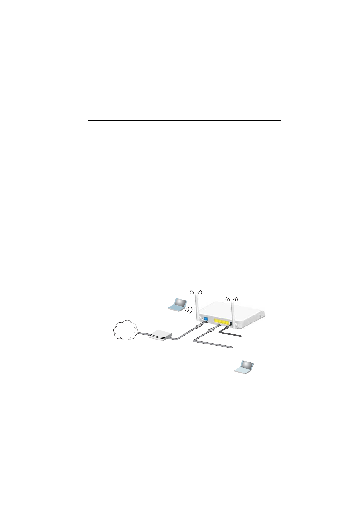
Gateway Mode
In its default Gateway Mode, the wireless AP/Router forwards traffic between an
Internet connected cable or ADSL modem, and wired or wireless PCs or notebooks.
The basic connections are illustrated in the figure below.
ïò
ݱ²²»½¬ ÉßÒ °±®¬ ¬±
½¿¾´»ñÜÍÔ³±¼»³
ìò
Í»¬ «° ©·®»´»-¼»ª·½»-
Ò±¬»¾±±µ ÐÝ
ײ¬»®²»¬
Э¿¾´»сЬНФУ±¼»³
Figure2-1. Gateway Mode Connection
íò
¿¼¿°¬»® ¬±
°±©»® -±«®½»
îò
ݱ²²»½¬ ÔßÒ °±®¬
¬± ÐÝ
2-1
Page 20

Installation
2
To connect the wireless AP/Router in Gateway Mode for use as an Internet gateway,
follow these steps:
1.Connect an Ethernet cable from the wireless AP/Router%s WAN port to your
Internet connected cable or ADSL modem.
2.Connect an Ethernet cable from the wireless AP/Router%s LAN port to your PC.
Alternatively, you can connect to a workgroup switch to support multiple users.
The wireless AP/Router can support up to 253 wired and wireless users.
3.Power on the wireless AP/Router by connecting the AC power adapter and
plugging it into a power source.
Caution: Use ONLY the power adapter supplied with the wireless AP/Router. Otherwise,
4.Set up wireless devices by pressing the WPS button on the wireless AP/Router
the product may be damaged.
When you power on the wireless AP/Router, verify that the Power LED turns on
and that the other LED indicators start functioning as described under "LED
Indicators# on page 1-3.
or by using the web interface. See "Initial Configuration# on page 4-1 for more
information on accessing the web interface.
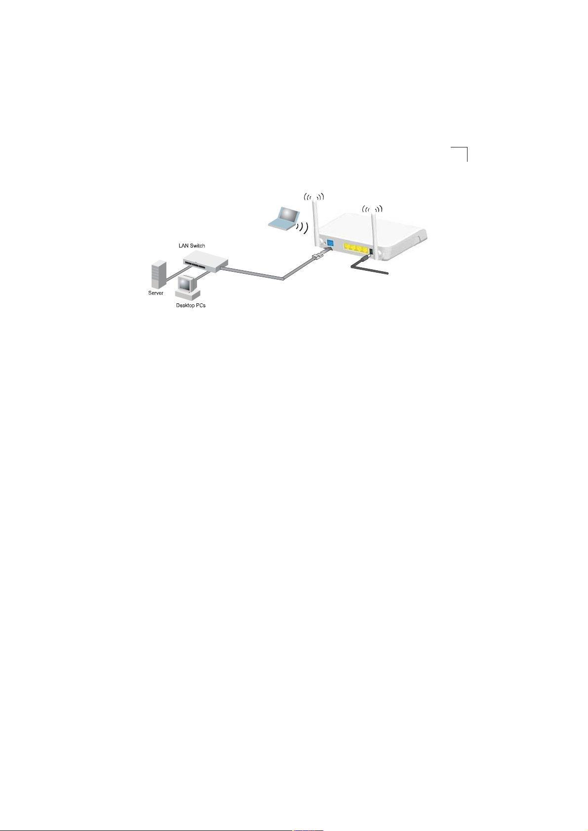
Bridge Mode
In Bridge Mode, the wireless AP/Router operates as a wireless access point,
extending a local wired network to associated wireless clients (PCs or notebooks
with wireless capability). From any nearby location, you can then make a wireless
connection to the wireless AP/Router and access the wired network resources,
including local servers and the Internet.
In Bridge Mode, the wireless AP/Router does not support gateway functions on its
WAN port. Both the LAN port and the WAN ports can be connected to a local
Ethernet LAN.
Note: Bridge Mode is not the factory default mode and must be manually set using the
web management interface.
2-2
Page 21
Bridge Mode
ݱ²²»½¬ßÝ °±©»®
íò
Í»¬ «° ©·®»´»-¼»ª·½»-
Ò±¬»¾±±µ ÐÝ
îò
¿¼¿°¬»® ¬±
ïò
ݱ²²»½¬ ÔßÒ ¿²¼ ÉßÒ
°±®¬- ¬± ¿² Û¬¸»®²»¬ ÔßÒ
-©·¬½¸ ±® ÐÝ-
Figure2-2. Bridge Mode Connection
To connect the wireless AP/Router for use as an access point, follow these steps:
1.Using Ethernet cables, connect the wireless AP/Router%s LAN and WAN ports
to PCs or a LAN switch.
2.Power on the wireless AP/Router by connecting the AC power adapter and
plugging it into a power source.
Caution: Use ONLY the power adapter supplied with the wireless AP/Router. Otherwise,
the product may be damaged.
°±©»® -±«®½»
2
When you power on the wireless AP/Router, verify that the Power LED turns on
and that the other LED indicators start functioning as described under "LED
Indicators# on page 1-3.
3.Set up wireless devices by pressing the WPS button on the wireless AP/Router
or by using the web interface. See "Initial Configuration# on page 4-1 for more
information on accessing the web interface.
2-3
Page 22

2
Installation
2-4
Page 23
Chapter 3: Network Planning
The wireless AP/Router is designed to be very flexible in its deployment options. It
can be used as an Internet gateway for a small network, or as an access point to
extend an existing wired network to support wireless users. It also supports use as a
wireless bridge to connect two wired LANs.
This chapter explains some of the basic features of the wireless AP/Router and
shows some network topology examples in which the device is implemented.
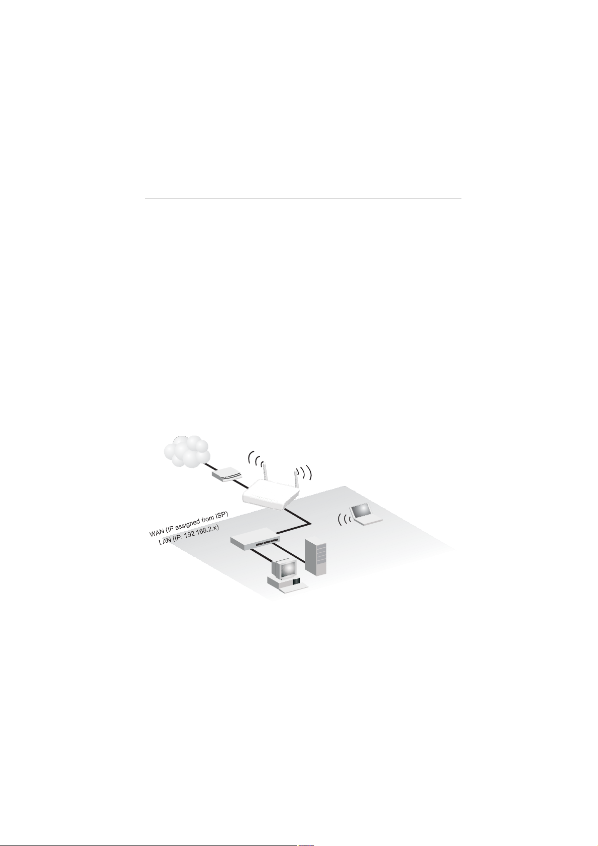
Internet Gateway Router
The wireless AP/Router can connect directly to a cable or DSL modem to provide an
Internet connection for multiple users through a single service provider account.
Users connect to the wireless AP/Router either through a wired connection to a LAN
port, or though the device%s own wireless network. The wireless AP/Router functions
as an Internet gateway when set to Gateway Mode.
An Internet gateway employs several functions that essentially create two separate
Internet Protocol (IP) subnetworks; a private internal network with wired and
wireless users, and a public external network that connects to the Internet. Network
traffic is forwarded, or routed, between the two subnetworks.
ײ¬»®²»¬
Í»®ª·½»
Ю±ª·¼»®
Ý¿¾´»ñÜÍÔ
Ó±¼»³
É·®»´»--ßÐñ᫬»®
Ò±¬»¾±±µ ÐÝ
шЧРж пзотпкитот¨ч
ÔßÒ Í©·¬½¸
Í»®ª»®
шЧРж пзотпкитот¨ч
Ü»-µ¬±° ÐÝ
шЧРж пзотпкитот¨ч
Figure3-1. Operating as an Internet Gateway Router
3-1
Page 24
Network Planning
3
The private local network, connected to the LAN port or wireless interface, provides
a Dynamic Host Configuration Protocol (DHCP) server for allocating IP addresses to
local PCs and wireless clients, and Network Address Translation (NAT) for mapping
the multiple "internal" IP addresses to one "external" IP address.
The public external network, connected to the WAN port, supports DHCP client,
Point-to-Point Protocol over Ethernet (PPPoE) and static IP for connection to an
Internet service provider (ISP) through a cable or DSL modem.
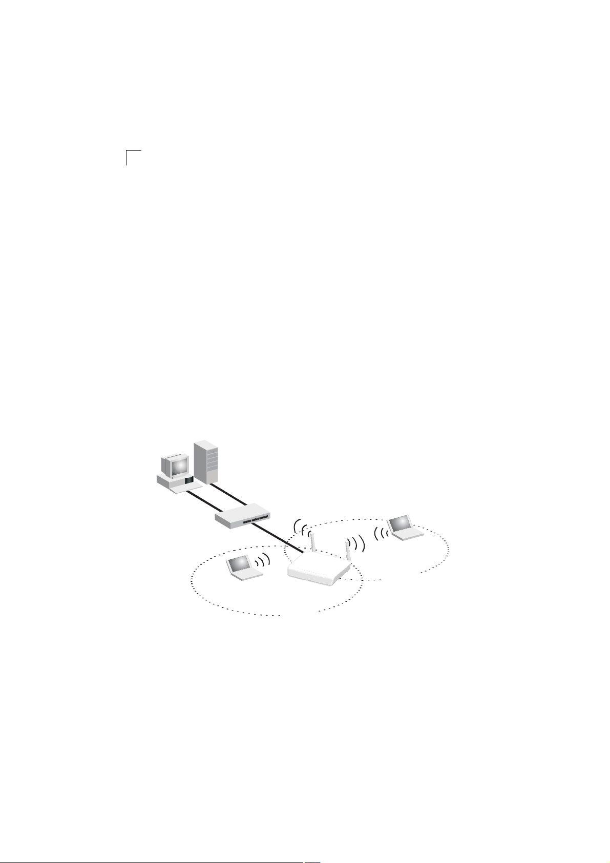
LAN Access Point
The wireless AP/Router can provide an access point service for an existing wired
LAN, creating a wireless extension to the local network. The wireless AP/Router
functions as purely an access point when set to Bridge Mode. When used in this
mode, there are no gateway functions between the WAN port and the LAN and
wireless interface.
A Wi-Fi wireless network is defined by its Service Set Identifier (SSID) or network
name. Wireless clients that want to connect to a network must set their SSID to the
same SSID of the network service. The wireless AP/Router supports two separate
wireless interfaces, that is two SSIDs or Virtual Access Points (VAPs). The two VAP
interfaces can be configured separately to support different security settings or other
wireless functions.
Ü»-µ¬±° ÐÝ
шЧРж пзотпкитот¨ч
3-2
Н»®ª»®
шЧРж пзотпкитот¨ч
ÔßÒ Í©·¬½¸
Ò±¬»¾±±µ ÐÝ
шЧРж пзотпкитот¨ч
É·®»´»--ßÐñ᫬»®
ÍÍ×Ü ï
ø°«¾´·½÷
Figure3-2. Operating as an Access Point
Ò±¬»¾±±µ ÐÝ
шЧРж пзотпкитот¨ч
ÍÍ×Ü î
ø°®·ª¿¬»÷
Page 25

Wireless Bridge
Wireless Bridge
The IEEE 802.11 standard defines a Wireless Distribution System (WDS) for bridge
connections between access points. The wireless AP/Router can use WDS to
forward traffic on links between units.
A single WDS bridge link can be specified for the WLAN1 interface. One end of a
link must be configured as the WDS Parent! and the other as the WDS Child.!
Note: The network domain of WDS child has to be the same as WDS parent.
3
ײ¬»®²»¬
Í»®ª·½»
Ю±ª·¼»®
Ý¿¾´»ñÜÍÔ
Ó±¼»³
ÉÜÍ Ý¸·´¼
ÉÜÍ Ð¿®»²¬
Ü»-µ¬±° ÐÝ
É·®»´»--ßÐñ᫬»®
øÞ®·¼¹» Ó±¼»÷
Í»®ª»®
шЧРж пзотпкитот¨ч
É·®»´»--ßÐñ᫬»®
øÙ¿¬»©¿§ Ó±¼»÷
ÔßÒ Í©·¬½¸
шЧРж пзотпкитот¨ч
Figure3-3. Operating as a Wireless Bridge
Ü»-µ¬±° ÐÝ
шЧРж пзотпкитот¨ч
3-3
Page 26

3
Network Planning
3-4
Page 27

Chapter 4: Initial Configuration
The wireless AP/Router offers a user-friendly web-based management interface for
the configuration of all the unit%s features. Any PC directly attached to the unit can
access the management interface using a web browser, such as Internet Explorer
(version 6.0 or above).
This chapter describes the wireless AP/Router%s configurable features, all of which
may be accessed through the web interface.
It is recommended to make initial configuration changes by connecting a PC directly
to one of the wireless AP/Router's LAN ports. The wireless AP/Router has a default
IP address of 192.168.2.1 and a subnet mask of 255.255.255.0. If your PC is set to
"Obtain an IP address automatically# (that is, set as a DHCP client), you can connect
immediately to the web interface. Otherwise, you must set your PC IP address to be
on the same subnet as the wireless AP/Router (that is, the PC and wireless AP/
Router addresses must both start 192.168.2.x).
To access the configuration menu, follow these steps:
1.Use your web browser to connect to the management interface using the
default IP address of 192.168.2.1.
2.Log into the wireless AP/Router management interface by entering the default
username "admin# and password "smcadmin#, then click OK.
Note: It is strongly recommended to change the default user name and password the
first time you access the web interface. For information on changing user names
and passwords, See "Administrator Settings# on page5-47.
Figure4-1. Login Page
4-1
Page 28
Initial Configuration
4
Using the Setup Wizard
There are only a few basic steps you need to set up the wireless AP/Router and
provide a connection for network access for other wireless stations.
The Setup Wizard takes you through configuration procedures for the general
network settings. Follow these steps:
1. Launch the Setup Wizard & Click "Setting Wizard# on the left side of the
screen to enter the setup wizard page. Click Next to begin the setup.
4-2
Figure4-2. Home Page
Page 29
Using the Setup Wizard
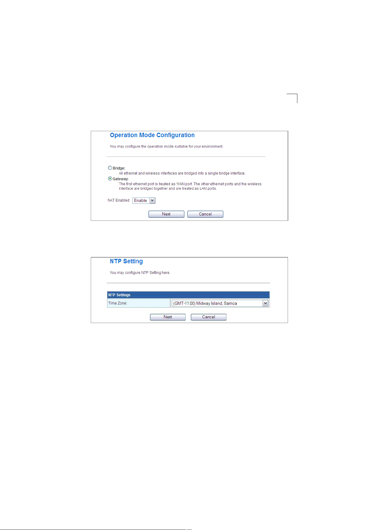
2. Operation Mode Configuration & Select the operation mode required for the
network environment.
Figure4-3. Setup Wizard - Operation Mode
3. NTP Setting & Select a time zone according to where the device is operated.
Click Next after completing the setup.
4
Figure4-4. Setup Wizard - NTP Setting
4-3
Page 30
Initial Configuration
4
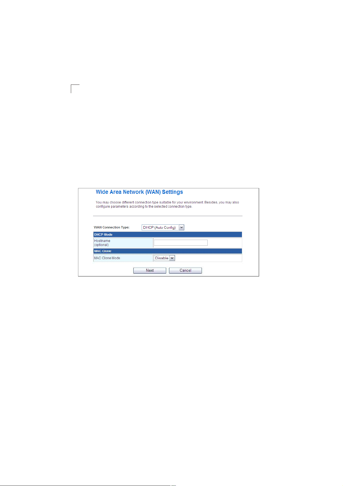
4. WAN Configuration & Specifies the Internet connection parameters for the
wireless AP/Router is WAN port. Click Next after completing the setup.
WAN Connection Type $ By default, the access point WAN port is configured with
DHCP enabled. After you have network access to the access point, you can use the
web browser interface to modify the initial IP configuration, if needed. The options
are Static IP, DHCP, PPPoE (ADSL), L2TP and PPTP. Each option changes the
parameters displayed below it. (Default: DHCP)
DHCP
Enables Dynamic Host Configuration Protocol (DHCP) for the WAN port. This
setting allows the wireless AP/Router to automatically obtain an IP address from a
DHCP server normally operated by the Internet Service Provider (ISP).
Figure4-5. Setup Wizard - WAN DHCP
! Hostname & The hostname of the DHCP client.
! MAC Clone Mode & Some ISPs limit Internet connections to a specified MAC
address of one PC. This setting allows you to manually change the MAC address
of the wireless AP/Router's WAN interface to match the PC's MAC address
provided to your ISP for registration. You can enter the registered MAC address
manually by typing it in the boxes provided. Otherwise, connect only the PC with
the registered MAC address to the wireless AP/Router, then click the "Fill My MAC#
(Default: Disable)
Note: If you are unsure of the PC MAC address originally registered by your ISP, call
your ISP and request to register a new MAC address for your account. Register
the default MAC address of the wireless AP/Router.
4-4
Page 31

Static IP
Configures a static IP for the WAN port.
Using the Setup Wizard
4
Figure4-6. Setup Wizard - WAN Static IP
! IP Address & The IP address of the wireless AP/Router. Valid IP addresses
consist of four decimal numbers, 0 to 255, separated by periods.
! Subnet Mask & The mask that identifies the host address bits used for routing to
specific subnets.
! Default Gateway & The IP address of the gateway router for the wireless AP/
Router, which is used if the requested destination address is not on the local
subnet.
! Primary DNS Server & The IP address of the Primary Domain Name Server on
the network. A DNS maps numerical IP addresses to domain names and can be
used to identify network hosts by familiar names instead of the IP addresses. If you
have one or more DNS servers located on the local network, type the IP addresses
in the text fields provided. Otherwise, leave the addresses as all zeros (0.0.0.0).
! Secondary DNS Server & The IP address of the Secondary Domain Name Server
on the network.
4-5
Page 32

Initial Configuration
4
! MAC Clone Mode & Some ISPs limit Internet connections to a specified MAC
address of one PC. This setting allows you to manually change the MAC address
of the wireless AP/Router's WAN interface to match the PC's MAC address
provided to your ISP for registration. You can enter the registered MAC address
manually by typing it in the boxes provided. Otherwise, connect only the PC with
the registered MAC address to the wireless AP/Router, then click the "Fill My MAC#
(Default: Disable)
PPPoE
Enable the wireless AP/Router IP address to be assigned automatically from an
Internet service provider (ISP) through an ADSL modem using Point-to-Point
Protocol over Ethernet (PPPoE).
Figure4-7. Setup Wizard - WAN PPPoE
! PPPoE Username & Sets the PPPoE user name for the WAN port.
(Default: pppoe_user; Range: 1~32 characters)
! PPPoE Password & Sets a PPPoE password for the WAN port.
(Default: pppoe_password; Range: 1~32 characters)
! Verify Password & Prompts you to re-enter your chosen password.
! MAC Clone Mode & Some ISPs limit Internet connections to a specified MAC
address of one PC. This setting allows you to manually change the MAC address
of the wireless AP/Router's WAN interface to match the PC's MAC address
provided to your ISP for registration. You can enter the registered MAC address
manually by typing it in the boxes provided. Otherwise, connect only the PC with
the registered MAC address to the wireless AP/Router, then click the "Fill My MAC#
(Default: Disable)
4-6
Page 33

Using the Setup Wizard
L2TP
Enables the Layer Two Tunneling Protocol (L2TP) for implementing virtual private
networks. The service is provided in many European countries.
4
Figure4-8. Setup Wizard - WAN L2TP
! Server IP & Sets the L2TP server IP Address.
(Default: l2tp_server; Range: 1~32 characters)
! Username & Sets the L2TP user name for the WAN port.
(Default: l2tp_user; Range: 1~32 characters)
Password & Sets a L2TP password for the WAN port. (Default: l2tp_password;
Range: 1~32 characters)
! Verify Password & Prompts you to re-enter your chosen password.
! Address Mode & Sets a L2TP network mode. (Default: Static)
! IP Address & Sets the static IP address. (Default: 0.0.0.0, available when L2TP
Network Mode is set to static IP.)
! Subnet Mask & Sets the static IP subnet mask. (Default: 255.255.255.0, available
when L2TP Network Mode is set to static IP.)
4-7
Page 34

Initial Configuration
4
! Default Gateway & The IP address of the gateway router for the wireless AP/
Router, which is used if the requested destination address is not on the local
subnet.
! MAC Clone Mode & Some ISPs limit Internet connections to a specified MAC
address of one PC. This setting allows you to manually change the MAC address
of the wireless AP/Router's WAN interface to match the PC's MAC address
provided to your ISP for registration. You can enter the registered MAC address
manually by typing it in the boxes provided. Otherwise, connect only the PC with
the registered MAC address to the wireless AP/Router, then click the "Fill My MAC#
(Default: Disable)
PPTP
Enables the Point-to-Point Tunneling Protocol (PPTP) for implementing virtual
private networks. The service is provided in many European countries.
4-8
Figure4-9. Setup Wizard - WAN PPTP
Page 35

Using the Setup Wizard
! Server IP & Sets the PPTP server IP Address. (Default: pptp_server)
! Username & Sets the PPTP user name for the WAN port.
(Default: pptp_user; Range: 1~32 characters)
! Password & Sets a PPTP password for the WAN port. (Default: pptp_password;
Range: 1~32 characters)
! Verify Password & Prompts you to re-enter your chosen password.
! Address Mode & Sets a PPTP network mode. (Default: Static)
! IP Address & Sets the static IP address. (Default: 0.0.0.0, available when PPTP
Network Mode is set to static IP.)
! Subnet Mask & Sets the static IP subnet mask. (Default: 255.255.255.0, available
when PPTP Network Mode is set to static IP.)
! Default Gateway & The IP address of the gateway router for the wireless AP/
Router, which is used if the requested destination address is not on the local
subnet.
! MAC Clone Mode & Some ISPs limit Internet connections to a specified MAC
address of one PC. This setting allows you to manually change the MAC address
of the wireless AP/Router's WAN interface to match the PC's MAC address
provided to your ISP for registration. You can enter the registered MAC address
manually by typing it in the boxes provided. Otherwise, connect only the PC with
the registered MAC address to the wireless AP/Router, then click the "Fill My MAC#
(Default: Disable)
5. Basic Wireless Settings & Configures the SSID and sets for the wireless
security policy. Click Apply after completing the setup.
4
Figure4-10. Setup Wizard - Basic Wireless Settings
4-9
Page 36

Initial Configuration
4
! Network Name (SSID) & The name of the wireless network service provided by
the VAP. Clients that want to connect to the network must set their SSID to the
same as that of the VAP interface. (Default: "WBR14S_N3_AP#; Range: 1-32
characters)
! Security Policy & Configures the security mode used by clients.
Security# on page5-30.
See "WLAN
4-10
Page 37

Chapter 5: System Configuration
The wireless AP/Router offers a user-friendly web-based management interface for
the configuration of all the unit%s features. Any PC directly attached to the unit can
access the management interface using a web browser, such as Internet Explorer
(version 6.0 or above).
This chapter describes the wireless AP/Router%s configurable features, all of which
may be accessed through the web interface.
It is recommended to make initial configuration changes by connecting a PC directly
to one of the wireless AP/Router's LAN ports. The wireless AP/Router has a default
IP address of 192.168.2.1 and a subnet mask of 255.255.255.0. If your PC is set to
"Obtain an IP address automatically# (that is, set as a DHCP client), you can connect
immediately to the web interface. Otherwise, you must set your PC IP address to be
on the same subnet as the wireless AP/Router (that is, the PC and wireless AP/
Router addresses must both start 192.168.2.x).
To access the configuration menu, follow these steps:
1.Use your web browser to connect to the management interface using the
default IP address of 192.168.2.1.
2.Log into the wireless AP/Router management interface by entering the default
username "admin# and password "smcadmin,# then click Login.
Note: It is strongly recommended to change the default user name and password the
first time you access the web interface. For information on changing user names
and passwords, See "Administrator Settings# on page5-47
Figure5-1. Login Page
5-1
Page 38

System Configuration
5
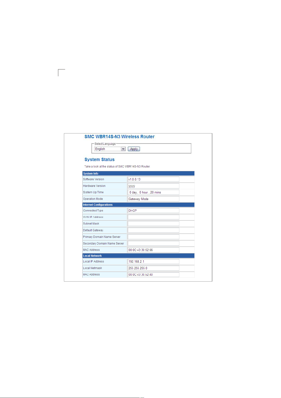
The System Information page displays the System, Internet Configuration, and Local
Network Settings.
Figure5-2. System Information (Gateway Mode)
The information in this chapter is organized to reflect the structure of the web
management screens for easy reference.
The Configuration pages include the options in the table below. For details on
configuration for each feature, see the corresponding page number.
Note: The displayed pages and settings may differ depending on whether the unit is in
Gateway or Bridge Mode.
5-2
Page 39

Table5-1. Advanced Settings
Menu Description ModePage
Operation Mode 5-4
Operation ModeSets the operating modes Both 5-4
Internet Settings 5-5
WAN Configures settings for the wide area network Gateway 5-5
LAN Sets the unit s IP address and enables DNS Gateway 5-13
Advanced RoutingConfigures Static and Dynamic Routing settings Gateway 5-15
QoS Configures Quality of Service (QoS) for wireless trafficGateway 5-17
ALG Enables the Application Layer Gateway (ALG) functionsGateway 5-18
Wireless Settings 5-19
Basic SettingConfigures wireless transmission method, frequency and
Advanced SettingConfigures advanced wireless transmission valuesBoth 5-25
Security Configures radio security parameters for the VAP interfaceBoth 5-30
WPS Configures WPS settings Both 5-37
Station ListDisplays the station list Both 5-39
Firewall 5-40
MAC/IP/Port
Filtering
Virtual ServerConfigures Virtual Server (Port Forwarding) settingsGateway 5-42
DMZ Configures the De-Militarized Zone settings Gateway 5-43
System SecurityEnables intrusion detection Gateway 5-44
Content FilteringConfigures content filtering settings Gateway 5-45
Administration 5-46
System
Management
Upgrade FirmwareUpgrades system software from a local file and enables
ConfigurationBackups and restores the configuration data and restores the
System StatusDisplays the current system status Both 5-50
StatisticsDisplays packet statistics Both 5-52
DHCP ClientsDisplays the DHCP clients table Both 5-53
System LogDisplays the system message log Both 5-54
Reboot Reboots the wireless AP/Router Both 5-54
SSID
Configures MAC/IP/Port filtering settings Gateway 5-40
Configures administrator account, password, Date/Time,
Dynamic DNS Settings and Green AP settings.
provisioning updates
factory defaults
Both 5-20
Both 5-46
Both 5-49
Both 5-50
5
5-3
Page 40

System Configuration
5
Operation Mode configuration
The Operation Mode Configuration pages allow you to setup the mode suitable for
your network environment.
Figure5-3. System Information (Gateway Mode)
! Bridge Mode & An access point mode that extends a wired LAN to wireless clients.
! Gateway Mode & Normal gateway mode that connects a wired LAN and wireless
clients to an Internet access device, such as a cable or DSL modem. This is the
factory set default mode.
! NAT & Enable NAT settings.
5-4
Page 41

Internet Settings
Internet Settings
The Internet Settings pages allow you to manage basic system configuration
settings.
Note: In Bridge mode, the wireless AP/Router%s Internet Settings options are
significantly reduced.
WAN Setting
Specifies the Internet connection parameters. Click on "Internet Settings# followed
by "WAN#.
WAN Connection Type $ By default, the access point WAN port is configured with
DHCP enabled. After you have network access to the access point, you can use the
web browser interface to modify the initial IP configuration, if needed. The options are
Static IP, DHCP, PPPoE (ADSL), L2TP, and PPTP. Each option changes the
parameters displayed below it. (Default: DHCP)
DHCP
Enables Dynamic Host Configuration Protocol (DHCP) for the WAN port. This
setting allows the wireless AP/Router to automatically obtain an IP address from a
DHCP server normally operated by the Internet Service Provider (ISP).
5
Figure5-4. Setup Wizard - WAN DHCP
5-5
Page 42

System Configuration
5
! Hostname (Optional) & The hostname of the DHCP client.
! MAC Clone Mode & Some ISPs limit Internet connections to a specified MAC
address of one PC. This setting allows you to manually change the MAC address
of the wireless AP/Router's WAN interface to match the PC's MAC address
provided to your ISP for registration. You can enter the registered MAC address
manually by typing it in the boxes provided. Otherwise, connect only the PC with
the registered MAC address to the wireless AP/Router, then click the "Fill My MAC#
(Default: Disable)
Note: If you are unsure of the PC MAC address originally registered by your ISP, call
your ISP and request to register a new MAC address for your account. Register
the default MAC address of the wireless AP/Router.
Static IP
Configures a static IP for the WAN port.
Figure5-5. Setup Wizard - WAN Static IP
! IP Address & The IP address of the wireless AP/Router. Valid IP addresses
consist of four decimal numbers, 0 to 255, separated by periods.
! Subnet Mask & The mask that identifies the host address bits used for routing to
specific subnets.
5-6
Page 43

Internet Settings
! Default Gateway & The IP address of the gateway router for the wireless AP/
Router, which is used if the requested destination address is not on the local
subnet.
! Primary DNS Server & The IP address of the Primary Domain Name Server on
the network. A DNS maps numerical IP addresses to domain names and can be
used to identify network hosts by familiar names instead of the IP addresses. If you
have one or more DNS servers located on the local network, type the IP addresses
in the text fields provided. Otherwise, leave the addresses as all zeros (0.0.0.0).
! Secondary DNS Server & The IP address of the Secondary Domain Name Server
on the network.
! MAC Clone Mode & Some ISPs limit Internet connections to a specified MAC
address of one PC. This setting allows you to manually change the MAC address
of the wireless AP/Router's WAN interface to match the PC's MAC address
provided to your ISP for registration. You can enter the registered MAC address
manually by typing it in the boxes provided. Otherwise, connect only the PC with
the registered MAC address to the wireless AP/Router, then click the "Fill My MAC#
(Default: Disable)
PPPoE
Enable the wireless AP/Router IP address to be assigned automatically from an
Internet service provider (ISP) through an ADSL modem using Point-to-Point
Protocol over Ethernet (PPPoE).
5
Figure5-6. Setup Wizard - WAN PPPoE
5-7
Page 44

System Configuration
5
! PPPoE Username & Sets the PPPoE user name for the WAN port.
(Default: pppoe_user; Range: 1~32 characters)
! PPPoE Password & Sets a PPPoE password for the WAN port.
(Default: pppoe_password; Range: 1~32 characters)
! Verify Password & Prompts you to re-enter your chosen password.
! Operation Mode & Selects the operation mode as Keep Alive, On Demand or
Manual. (Default: Keep Alive)
- Keep Alive Mode: The wireless AP/Router will periodically check your Internet
connection and automatically re-establish your connection when disconnected.
(Default: 60 seconds)
- On Demand Mode: The maximum length of inactive time the unit will stay
connected to the DSL service provider before disconnecting. This feature only
works when Connect Type is set to "Auto-Connect.# (Default: 5 minutes)
! MAC Clone Mode & Some ISPs limit Internet connections to a specified MAC
address of one PC. This setting allows you to manually change the MAC address
of the wireless AP/Router's WAN interface to match the PC's MAC address
provided to your ISP for registration. You can enter the registered MAC address
manually by typing it in the boxes provided. Otherwise, connect only the PC with
the registered MAC address to the wireless AP/Router, then click the "Fill My MAC#
(Default: Disable)
5-8
Page 45

Internet Settings
L2TP
Enables the Layer Two Tunneling Protocol (L2TP) for implementing virtual private
networks. The service is provided in many European countries.
5
Figure5-7. Setup Wizard - WAN L2TP
! Server IP & Sets the L2TP server IP Address.
(Default: l2tp_server; Range: 1~32 characters)
! Username & Sets the L2TP user name for the WAN port.
(Default: l2tp_user; Range: 1~32 characters)
Password & Sets a L2TP password for the WAN port. (Default: l2tp_password;
Range: 1~32 characters)
! Verify Password & Prompts you to re-enter your chosen password.
! Address Mode & Sets a L2TP network mode. (Default: Static)
! IP Address & Sets the static IP address. (Default: 0.0.0.0, available when L2TP
Network Mode is set to static IP.)
5-9
Page 46

System Configuration
5
! Subnet Mask & Sets the static IP subnet mask. (Default: 255.255.255.0, available
when L2TP Network Mode is set to static IP.)
! Default Gateway & The IP address of the gateway router for the wireless AP/
Router, which is used if the requested destination address is not on the local
subnet.
! Operation Mode & Selects the operation mode as Keep Alive, On Demand or
Manual. (Default: Keep Alive)
- Keep Alive Mode: The wireless AP/Router will periodically check your Internet
connection and automatically re-establish your connection when disconnected.
(Default: 60 seconds)
- On Demand Mode: The maximum length of inactive time the unit will stay
connected to the DSL service provider before disconnecting. This feature only
works when Connect Type is set to "Auto-Connect.# (Default: 5 minutes)
! MAC Clone Mode & Some ISPs limit Internet connections to a specified MAC
address of one PC. This setting allows you to manually change the MAC address
of the wireless AP/Router's WAN interface to match the PC's MAC address
provided to your ISP for registration. You can enter the registered MAC address
manually by typing it in the boxes provided. Otherwise, connect only the PC with
the registered MAC address to the wireless AP/Router, then click the "Fill My MAC#
(Default: Disable)
5-10
Page 47

Internet Settings
PPTP
Enables the Point-to-Point Tunneling Protocol (PPTP) for implementing virtual
private networks. The service is provided in many European countries.
5
Figure5-8. Setup Wizard - WAN PPTP
! Server IP & Sets a PPTP server IP Address. (Default: pptp_server)
! Username & Sets the PPTP user name for the WAN port.
(Default: pptp_user; Range: 1~32 characters)
! Password & Sets a PPTP password for the WAN port. (Default: pptp_password;
Range: 1~32 characters)
! Verify Password & Prompts you to re-enter your chosen password.
! Address Mode & Sets a PPTP network mode. (Default: Static)
! IP Address & Sets the static IP address. (Default: 0.0.0.0, available when PPTP
Network Mode is set to static IP.)
! Subnet Mask & Sets the static IP subnet mask. (Default: 255.255.255.0, available
when PPTP Network Mode is set to static IP.)
5-11
Page 48

System Configuration
5
! Default Gateway & The IP address of the gateway router for the wireless AP/
Router, which is used if the requested destination address is not on the local
subnet.
! Operation Mode & Selects the operation mode as Keep Alive, On Demand or
Manual. (Default: Keep Alive)
- Keep Alive Mode: The wireless AP/Router will periodically check your Internet
connection and automatically re-establish your connection when disconnected.
(Default: 60 seconds)
- On Demand Mode: The maximum length of inactive time the unit will stay
connected to the DSL service provider before disconnecting. This feature only
works when Connect Type is set to "Auto-Connect." (Default: 5 minutes)
! MAC Clone Mode & Some ISPs limit Internet connections to a specified MAC
address of one PC. This setting allows you to manually change the MAC address
of the wireless AP/Router's WAN interface to match the PC's MAC address
provided to your ISP for registration. You can enter the registered MAC address
manually by typing it in the boxes provided. Otherwise, connect only the PC with
the registered MAC address to the wireless AP/Router, then click the "Fill My MAC#
(Default: Disable)
5-12
Page 49

Internet Settings
LAN Setting
The wireless AP/Router must have a valid IP address for management using a web
browser and to support other features. The unit has a default IP address of
192.168.2.1. You can use this IP address or assign another address that is
compatible with your existing local network. Click on "Internet Settings# followed by
"LAN.#
5
Figure5-9. LAN Settings (Gateway Mode)
5-13
Page 50

System Configuration
5
! LAN IP Address & Valid IP addresses consist of four decimal numbers, 0 to 255,
separated by periods. The default setting is 192.168.2.1.
! Subnet Mask & Indicate the local subnet mask. (Default: 255.255.255.0.)
! MAC Address & The shared physical layer address for the wireless AP/Router%s
LAN ports.
! DHCP Type & Select this option to obtain the IP settings for the access point from
a DHCP (Dynamic Host Configuration Protocol) server. The IP address, subnet
mask, default gateway, and Domain Name Server (DNS) address are dynamically
assigned to the access point by the network DHCP server. (Options: Server/
Disable)
! Start/End IP Address & Specify the start and end IP addresses of a range that the
DHCP server can allocate to DHCP clients. Note that the address pool range is
always in the same subnet as the unit%s IP setting. The maximum clients that the
unit can support is 253.
! Primary DNS Server & The IP address of Domain Name Servers on the network.
A DNS maps numerical IP addresses to domain names and can be used to identify
network hosts by familiar names instead of the IP addresses.
! Secondary DNS Server & The IP address of the Secondary Domain Name Server
on the network.
! Default Gateway & The default gateway is the IP address of the router for the
wireless AP/Router, which is used if the requested destination address is not on
the local subnet.
! Lease Time & Select a time limit for the use of an IP address from the IP pool.
When the time limit expires, the client has to request a new IP address. The lease
time is expressed in seconds. (Default: 86400 seconds; Range: 60~864000
seconds)
! Statically Assigned & Up to three devices with specific MAC addresses can be
assigned static IP addresses. That is, the DHCP server always assigns these
devices the same IP addresses.
! LLTD & Link Layer Topology Discovery (LLTD) is a Microsoft proprietary discovery
protocol which can be used for both wired and wireless networks. (Options:
Disable/Enable, Default: Disable)
! IGMP Proxy & Enables IGMP proxy on the wireless AP/Router. (Options: Disable/
Enable, Default: Disable)
! UPNP & Allows the device to advertise its UPnP capabilities. (Default: Disable)
! Router Advertisement & Enables the sending and receiving of routing
advertisements to discover the existence of neighboring routers. (Options: Disable/
Enable, Default: Disable)
! PPPoE Relay & When enabled, the wireless AP/Router will forward PPPoE
messages to clients. Clients are then able to connect to the PPPoE service through
the WAN port. (Options: Disable/Enable, Default: Disable)
5-14
Page 51

Internet Settings
! DNS Proxy & Enables DNS proxy on the LAN port. DNS Proxy receives DNS
queries from the local network and forwards them to an Internet DNS server.
(Default: Disable)
Advanced Routing
Routing setup allows a manual method to set up routing between networks. The
network administrator configures static routes by entering routes directly into the
routing table. Static routing has the advantage of being predictable and easy to
configure.
Static Routing Settings
This screen is used to manually configure static routes to other IP networks,
subnetworks, or hosts. Click "Internet Settings# followed by "Advanced Routing#.
(Maximum 32 entries are allowed.)
5
Figure5-10. Static Route (Gateway Mode)
! Destination & A destination network or specific host to which packets can be
routed.
! Type & Defines the type of destination. (Options: Host/Net, Default: Host)
! Gateway & The IP address of the router at the next hop to which matching frames
are forwarded.
! Interface & The selected interface to which a static routing subnet is to be applied.
Comment & Enters a useful comment to help identify this route.
5-15
Page 52

System Configuration
5
Routing Table
This page displays the information necessary to forward a packet along the best
path toward its destination. Each packet contains information about its origin and
destination. When a packet is received, a network device examines the packet and
matches it to the routing table entry providing the best match for its destination. The
table then provides the device with instructions for sending the packet to the next
hop on its route across the network.
Note: The Routing Table is only available when the wireless AP/Router is set to
Gateway Mode.
Figure5-11. Routing Table (Gateway Mode)
Destination & Displays all destination networks or specific hosts to which packets
can be routed.
Netmask & Displays the subnetwork associated with the destination.
! Gateway & Displays the IP address of the router at the next hop to which matching
frames are forwarded.
! Flags & Possible flags include: 1: U, 3: UG, 5: UH, 7: UGH, 0: ! (Definition: U: route
is up, H: target is a host, G: use gateway and !: Reject route.)
! Metric & A number used to indicate the cost of the route so that the best route,
among potentially multiple routes to the same destination, can be selected.
! Ref & Number of references to this route.
! Use & Count of lookups for the route.
! Interface & Interface to which packets for this route will be sent.
Comment & Displays a useful comment to identify the routing rules.
5-16
Page 53

Internet Settings
Dynamic Route
The wireless AP/Router supports RIP 1 and RIP 2 dynamic routing protocol. Routing
Information Protocol (RIP) is the most widely used method for dynamically
maintaining routing tables. RIP uses a distance vector-based approach to routing.
Routes are chosen to minimize the distance vector, or hop count, which serves as a
rough estimate of transmission cost. Each router broadcasts its advertisement every
30 seconds, together with any updates to its routing table. This allows all routers on
the network to build consistent tables of next hop links which lead to relevant
subnets.
Figure5-12. Dynamic Route (Gateway Mode)
RIP Enables or disable the RIP protocol for the WAN or LAN interface. (Options:
Disable/v1/v2, Default: Disable)
QoS Setting
The QoS setting page is used to configure Quality of Service (QoS) for Traffic
Prioritization and Bandwidth Management. Quality of Service (QoS) provides users
the control over which type of outgoing data traffic is given priority by the router. The
throughput rate of the upload data passed through the wireless AP/Router can be
throttled. Click on !Internet Settings" followed by !QoS".
5
Figure5-13. QoS Settings (Gateway Mode)
5-17
Page 54

System Configuration
5
Bandwidth QoS Setting $ The maximum upload speed of the Internet connection
on the WAN port.
! Quality of Service & Enables the QoS. (Default: Enable)
! Upload Bandwidth & Sets the maximum upload bandwidth. (Default: user
defined)
ALG
The application gateway settings provide a filter for certain protocol data (such as
FTP and SIP) to pass through the wireless AP/Router NAT and firewall restrictions.
5-18
Figure5-14. ALG Settings
Page 55

Wireless Settings
FTP Support & Allows FTP packets to pass through the wireless AP/Router.
! TFTP Support & Allows TFTP packets to pass through the wireless AP/Router.
H.323 Support & Allows H.323 packets to pass through the wireless AP/Router to
support audio, data and video conferencing for teleconferencing.
! SIP Support & Allows SIP packets to pass through the wireless AP/Router.
VPN-passthrough Support (L2TP, IPSEC, PPTP) & Allows L2TP, IPSec, and
PPTP packets to pass through the wireless AP/Router.
Wireless Settings
The IEEE 802.11n interfaces include configuration options for radio signal
characteristics and wireless security features.
The wireless AP/Router can operate in five modes, mixed 802.11b/g/n, mixed
802.11b/g, 802.11b only, 802.11g only or 802.11n only. Also note that 802.11g is
backward compatible with 802.11b, and 802.11n is backward compatible with both
802.11b/g at slower data transmit rates.
Each radio supports two virtual access point (VAP) interfaces, referred to as WLAN1
and WLAN2. Each VAP functions as a separate access point, and can be configured
with its own Service Set Identification (SSID) and security settings. However, most
radio signal parameters apply to both VAP interfaces. The configuration options are
nearly identical, and are therefore both covered in this section of the manual.
Traffic to specific VAPs can be segregated based on user groups or application
traffic. Both VAPs can have up to 64 wireless clients, whereby the clients associate
with these VAPs the same as they would with a physical access point.
Note: The radio channel settings for the access point are limited by local regulations,
which determine the number of channels that are available. See "Specifications#
on pageB-1 for additional information on the maximum number channels
available.
5
5-19
Page 56

System Configuration
5
Basic Settings
The Basic Setting page allows you to enable the wireless interface, select which
radio mode to use, choose the transmit frequency and configure SSIDs.
Click on "Wireless Settings,# followed by "Basic#.
Note: There are several variables to consider when selecting a radio mode that make it
fully functional. Simply selecting the mode you want is not enough to ensure full
compatibility for that mode. Information on these variables may be found in the
Advanced Setting section.
Figure5-15. Basic Wireless Settings
! Radio On/Off & Enables or Disable the radio. (Default: Enable)
! Network Mode & Defines the radio mode for the VAP interface.
(Default: 802.11b/g/n Mixed)
Note: Enabling the wireless AP/Router to communicate with 802.11b/g clients in both
802.11b/g/n Mixed and 802.11n modes also requires that HT Operation in the
Advanced Settings menu be set to Mixed. Setting HT Operation to Green Field is
exclusive for 802.11n client communication only and prevents 802.11 b/g
communication.
5-20
Page 57

Wireless Settings
- 802.11b/g Mixed: Both 802.11b and
802.11g clients can communicate with
the wireless AP/Router (up to 108
Mbps), but data transmission rates may
be slowed to compensate for 802.11b
clients. Any 802.11n clients will also be
able to communicate with the wireless AP/Router, but they will be limited to
802.11g protocols and data transmission rates.
- 802.11b only: All 802.11b, 802.11g, and 802.11n clients will be able to
communicate with the wireless AP/Router, but the 802.11g and 802.11n clients
will be limited to 802.11b protocols and data transmission rates (up to 11 Mbps).
- 802.11g only: Both 802.11g and 802.11n clients will be able to communicate
with the wireless AP/Router, but the 802.11n clients will be limited to 802.11g
protocols and data transmission rates (up to 54 Mbps). Any 802.11b clients will
not be able to communicate with the wireless AP/Router.
- 802.11b/g/n Mixed: All 802.11b/g/n clients can communicate with the wireless
AP/Router (up to 300 Mbps), but data transmission rates may be slowed to
compensate for 802.11b/g clients.
Network Name (SSID) & The name of the wireless network service provided by
the VAP. Clients that want to connect to the network must set their SSID to the
same as that of the VAP interface. (Default: "WBR14S_N3_AP#; Range: 1-32
characters)
- Multiple SSID & The number of wireless network interfaces (SSIDs) supported
on the device.
Broadcast Network Name (SSID) & The wireless AP/Router will broadcast its
SSID.
AP Isolation & The wireless AP/Router will isolate wireless clients in order to
protect them. Normally for users who are at hotspots
! MBSSID AP Isolation & The wireless AP/Router will isolate wireless clients from
different SSID.
! BSSID & The identifier (MAC address) of a wireless AP/Router in a Basic Service
Set (BSS) network.
! WLAN Frequency & The radio channel
that the wireless AP/Router uses to
communicate with wireless clients. When
multiple access points are deployed in the
same area, set the channel on
neighboring access points at least five
channels apart to avoid interference with
each other. For example, you can deploy
up to three access points in the same area
using channels 1, 6, 11. Note that wireless clients automatically set the channel to
the same as that used by the wireless AP/Router to which it is linked. Selecting
Auto Select enables the wireless AP/Router to automatically select an unoccupied
5
5-21
Page 58

System Configuration
5
radio channel. (The supported channels are dependent on the country code
setting.)
Wireless Distribution System (WDS)
The WLAN1 radio interface can be configured to operate in a mode that allows it to
forward traffic directly to other access point units. To set up links between access
point units, you must configure the Wireless Distribution System (WDS) forwarding
table by specifying the wireless MAC address of all units to which you want to
forward traffic.
Traffic forwarded to WDS links is automatically converted to 802.11 four-address
format frame. This uses the MAC addresses of the station and that of the AP
connected to it on the transmitting LAN, and the MAC addresses of the AP
functioning as a wireless repeater/bridge and that of the station connected to it on a
neighboring LAN in the 802.11 frame header. Ethernet traffic follows a three-address
format that is reconstructed for WDS transmission. The wireless AP/Router will
reconstruct the frame format upon receival and transmission using the criteria of the
receiving and forwarding port location and whether it is Ethernet or wireless in type.
Note: The wireless AP/Router does not support the spanning tree algorithm. WDS links
should be configured appropriately to avoid causing loops on the network.
Up to four WDS links can be specified for each unit in the WDS network.
The WDS link can be configured in the following combinations:
1.Both two units are configured as Gateway Mode
2.One unit is Gateway Mode and one unit is Bridge Mode
3.Both two units are configured as Bridge Mode
When both units are set to Gateway Mode, be sure to check these settings:
! Be sure each unit is configured with a different LAN IP address.
! Be sure that only one unit has Internet access on its WAN port.
! Be sure the DHCP server is enabled only on one unit. If one unit is providing
Internet access, enable the DHCP server on that unit.
Note: WDS Settings only apply to WLAN1. WLAN2 is pre-configured to Bridge mode
unless WLAN1 is configured to act as a bridge, in which case WLAN2 is disabled.
Figure5-16. WDS Settings
5-22
Page 59

Wireless Settings
WDS Setting $ Configures WDS related parameters. Up to four MAC addresses
can be specified for each unit in the WDS network. WDS links may either be
manually configured (Bridge and Repeater modes) or auto-discovered (Lazy mode).
! WDS Mode & Selects the WDS mode of WLAN1. (Options: Disable/Lazy/Bridge/
Repeater. Default: Disable)
- Disable: WDS is disabled.
- Lazy: Operates in an automatic mode that detects and learns WDS peer
addresses from received WDS four-address format frame packets, without the
need to configure a WDS MAC list entry. This feature allows the wireless AP/
Router to associate with other wireless AP/Routers in the network and use their
WDS MAC list. In Lazy mode the wireless AP/Router sends a beacon.
- Bridge: Operates as a standard bridge that forwards traffic between WDS links
(links that connect to other AP/wireless bridges, or units in Repeater or Lazy
mode) and an Ethernet port. Only data destined for stations which are known to
be on the peer Ethernet link, multicast data or data with unknown destinations,
need to be forwarded through the WDS link. The Bridge mode does not transmit
a beacon, unlike the other three modes. In this mode the wireless AP/Router
may also function as a repeater.
Note: Enabling "Bridge# mode disables WLAN2.
- Repeater: Operates as a wireless repeater, extending the range for remote
wireless clients and connecting them to an AP connected to the wired network.
WDS peers must be registered with the wireless AP/Router. Repeater mode
also supports the dual capability of the VAP functioning as an AP. In this mode,
traffic is not forwarded to the Ethernet port from the radio interface. In Repeater
mode the wireless AP/Router transmits a beacon.
5
HT Physical Mode Settings
Figure5-17. HT Physical Mode Settings
5-23
Page 60

System Configuration
5
! HT Operation Mode & Packets from 802.11n clients are referred to as High
Throughput (HT) Greenfield packets, in other words packets that can be
transmitted at rates of up to 300 Mbps assuming that HT Channel Bandwidth is set
to 20/40Mhz, see HT Channel Bandwidth next page.
Note: Some 802.11n wireless clients may be capable of transmission rates of up to
600 Mbps, however the wireless AP/Router will only be able to connect to them at
a maximum transmission rate of 300 Mbps.
802.11b/g packets are referred to as non-HT packets, being transmitted at lower
throughput rates. HT mixed format frames contain a preamble compatible with the
non-HT receivers. HT Greenfield frames do not contain a non-HT compatible part.
Support for HT Greenfield format is optional. An HT station that does not support
the reception of an HT Greenfield format frame must be able to detect that an HT
Greenfield format frame is an HT transmission (as opposed to a non-HT
transmission). In this case the receiver must decode the high throughput signal
(HT-SIG) in the packet header and determine if the HT-SIG cyclic redundancy
check (CRC) passes. (Default: Mixed)
! HT Channel Bandwidth & The wireless AP/Router provides a channel bandwidth
of 40 MHz by default giving an 802.11g connection speed of 108 Mbps (sometimes
referred to as Turbo Mode) and a 802.11n connection speed of up to 300 Mbps.
Setting the HT Channel Bandwidth to 20 MHz slows connection speed for 802.11g
and 802.11n to 54 Mbps and 74 Mbps respectively and ensures backward
compliance for slower 802.11b devices. (Default: 20/40MHz)
! Guard Interval & The guard interval between symbols helps receivers overcome
the effects of multipath delays. When you add a guard time, the back portion of
useful signal time is copied and appended to the front. (Default: Auto)
! MCS & The Modulation and Coding Scheme (MCS) is a value that determines the
modulation, coding and number of spatial channels. (Options: value [range] = 0~7
(1 Tx Stream), 8~15 (2 TxStream), 32 and auto (33). Default: auto)
! Reverse Direction Grant (RDG) & When enables Reverse Direction Grant, the
wireless AP/Router can reduce the transmitted data packet collision by using the
reverse direction protocol. During TXOP (Transmission Opportunity) period, the
receiver could use remaining transmission time to transmit data to a sender. The
RDG improves transmission performance and scalability in a wireless
environment.
! Extension Channel & When 20/40MHz channel bandwidth has been set, the
extension channel option will be enabled. The extension channel will allow you to
get extra bandwidth. (Options: 2417MHz/Channel 2, 2457MHz/Channel 10.
Default: 2457MHz/Channel 10.)
! Aggregate MSDU (A-MSDU) & This option enables Mac Service Data Unit
(MSDU) aggregation. (Default: Disable)
! Auto Block ACK & Select to block ACK (Acknowledge Number) or not during data
transferring.
! Decline BA Request & Select to reject peer BA-Request or not.
5-24
Page 61

Wireless Settings
Other HT Settings
Figure5-18. HT Physical Mode Settings
! HT TxStream & HT means High Throughput. The number of HT TxStream means
how many antennas will transmit data simultaneously. (Options: 1 or 2. Default: 2)
! HT RxStream & The number of HT RxStream means how many antennas will
receive data simultaneously. (Options: 1 or 2. Default: 2)
Advanced Wireless Settings
The Advanced Setting page allows you to configure the more advanced radio
settings, many of which are enabled by default.
Click "Wireless Settings# followed by "Advanced#.
5
Figure5-19. Advanced Wireless Settings
5-25
Page 62

System Configuration
5
! BG Protection & Enables a backward
compatible protection system for
802.11b clients. There are three modes.
(Default: Auto):
- Auto: The wireless AP/Router enables
its protection mechanism for 802.11b
clients when they are detected in the network. When 802.11b clients are not
detected, the protection mechanism is disabled.
- On: Forces the unit to always use protection for 802.11b clients, whether they
are detected in the network or not.
- Off: Forces the unit to never use protection for 802.11b clients. This prevents
802.11b clients from connecting to the network.
Note: Enabling "On# b/g Protection can slow throughput for 802.11g/n clients by as
much as 50%.
! Beacon Interval & The rate at which beacon signals are transmitted from the
access point. The beacon signals allow wireless clients to maintain contact with the
access point. They may also carry power-management information. (Range:
20-999 TUs; Default: 100 TUs)
! Data Beacon Rate (DTIM) & The rate at which stations in sleep mode must wake
up to receive broadcast/multicast transmissions. Known also as the Delivery Traffic
Indication Map (DTIM) interval, it indicates how often the MAC layer forwards
broadcast/multicast traffic, which is necessary to wake up stations that are using
Power Save mode. The default value of 2 indicates that the access point will save
all broadcast/multicast frames for the Basic Service Set (BSS) and forward them
after every second beacon. Using smaller DTIM intervals delivers broadcast/
multicast frames in a more timely manner, causing stations in Power Save mode
to wake up more often and drain power faster. Using higher DTIM values reduces
the power used by stations in Power Save mode, but delays the transmission of
broadcast/multicast frames. (Range: 1-255 beacons; Default: 1 beacon)
! Fragment Threshold & Configures the minimum packet size that can be
fragmented when passing through the access point. Fragmentation of the PDUs
(Package Data Unit) can increase the reliability of transmissions because it
increases the probability of a successful transmission due to smaller frame size. If
there is significant interference present, or collisions due to high network utilization,
try setting the fragment size to send smaller fragments. This will speed up the
retransmission of smaller frames. However, it is more efficient to set the fragment
size larger if very little or no interference is present because it requires overhead
to send multiple frames. (Range: 256-2346 bytes; Default: 2346 bytes)
5-26
Page 63

Wireless Settings
! RTS Threshold & Sets the packet size threshold at which a Request to Send
(RTS) signal must be sent to a receiving station prior to the sending station starting
communications. The access point sends RTS frames to a receiving station to
negotiate the sending of a data frame. After receiving an RTS frame, the station
sends a CTS (clear to send) frame to notify the sending station that it can start
sending data. If the RTS threshold is set to 0, the access point always sends RTS
signals. If set to 2347, the access point never sends RTS signals. If set to any other
value, and the packet size equals or exceeds the RTS threshold, the RTS/CTS
(Request to Send / Clear to Send) mechanism will be enabled. The access points
contending for the medium may not be aware of each other. The RTS/CTS
mechanism can solve this "Hidden Node Problem.# (Range: 0-2347 bytes)
! TX Power & Adjusts the power of the radio signals transmitted from the access
point. The higher the transmission power, the farther the transmission range.
Power selection is not just a trade off between coverage area and maximum
supported clients. You also have to ensure that high-power signals do not interfere
with the operation of other radio devices in the service area. (Options: 100%, 50%,
25%, 12%, minimum; Default: 100%)
! Short Preamble & Enables the length of the signal preamble that is used at the
start of a data transmission. (Default: Disable)
! Short Slot & Sets the basic unit of time the wireless AP/Router%s uses for
calculating waiting times before data is transmitted. Enabling a short slot time can
increase data throughput on the wireless AP/Router, but requires that all clients
can support a short slot time (that is, 802.11g-compliant clients must support a
short slot time). (Default: Enable)
! Tx Burst & Enables data transmission bursting to boost throughput for high data
transmissions. (Default: Enable)
! Pkt_aggregation & Enables grouping together of some packets and sending them
together to boost bandwidth. (Default: Enable)
5
Configuring Wi-Fi Multimedia
Wireless networks offer an equal opportunity for all devices to transmit data from
any type of application. Although this is acceptable for most applications, multimedia
applications (with audio and video) are particularly sensitive to the delay and
throughput variations that result from this equal opportunity wireless access method.
For multimedia applications to run well over a wireless network, a Quality of Service
(QoS) mechanism is required to prioritize traffic types and provide an enhanced
opportunity wireless access method. The access point implements QoS using the
Wi-Fi Multimedia (WMM) standard. Using WMM, the access point is able to prioritize
traffic and optimize performance when multiple applications compete for wireless
network bandwidth at the same time. WMM employs techniques that are a subset of
the developing IEEE 802.11e QoS standard and it enables the access point to inter
operate with both WMM enabled clients and other devices that may lack any WMM
functionality.
5-27
Page 64

System Configuration
5
Figure5-20. Wi-Fi Multimedia Settings
! WMM Capable & Wi-Fi Multimedia (WMM), also known as Wireless Multimedia
Extensions (WME), is a Wi-Fi Alliance interoperability certification. It provides basic
Quality of Service (QoS) features for IEEE 802.11 wireless network. Enabling
WMM support provides prioritization of Wi-Fi data packets on four categories
voice, video, best effort, and background. (Default: Enabled)
! APSD Capable & Auto Power Save Delivery is used for saving power
consumption. APSD allows a longer beacon interval until the traffic arrives.
(Default: Disable., See "Beacon Interval# on page 5-26)
! DLS Capable & The Direct Link Setup (DLS) allows all clients transfer data more
effectively. When enables DLS, the wireless AP/Router will all clients on this unit to
establish directly connection and speed up the data transmission, especially for
multimedia data files. (Default: Disable)
WMM Parameters & Display the WMM Parameters.
Access Categories ! WMM defines four access categories (ACs): voice, video,
best effort, and background. These categories correspond to traffic priority levels
and are mapped to IEEE 802.1D priority tags (see Table 5-1). The direct mapping of
the four ACs to 802.1D priorities is specifically intended to facilitate inter operability
with other wired network QoS policies. While the four ACs are specified for specific
types of traffic, WMM allows the priority levels to be configured to match any
network-wide QoS policy. WMM also specifies a protocol that access points can use
to communicate the configured traffic priority levels to QoS-enabled wireless clients.
Table5-2. WMM Access Categories
Access CategoryWMM DesignationDescription 802.1D Tags
AC_VO (AC3) Voice Highest priority, minimum delay. Time-sensitive
AC_VI (AC2) Video High priority, minimum delay. Time-sensitive data
data such as VoIP (Voice over IP) calls.
such as streaming video.
7, 6
5, 4
5-28
Page 65

Wireless Settings
Table5-2. WMM Access Categories
Access CategoryWMM DesignationDescription 802.1D Tags
AC_BE (AC0) Best EffortNormal priority, medium delay and throughput.
AC_BK (AC1) BackgroundLowest priority. Data with no delay or throughput
WMM Operation $ WMM uses traffic priority based on the four ACs; Voice, Video,
Best Effort, and Background. The higher the AC priority, the higher the probability
that data is transmitted. When the access point forwards traffic, WMM adds data
packets to four independent transmit queues, one for each AC, depending on the
802.1D priority tag of the packet. Data packets without a priority tag are always
added to the Best Effort AC queue. From the four queues, an internal "virtual#
collision resolution mechanism first selects data with the highest priority to be
granted a transmit opportunity. Then the same collision resolution mechanism is
used externally to determine which device has access to the wireless medium.
Data only affected by long delays. Data from
applications or devices that lack QoS capabilities.
requirements, such as bulk data transfers.
0, 3
2, 1
5
Figure5-21. WMM Parameters
WMM Acknowledge Policy & By default, all wireless data transmissions require the
sender to wait for an acknowledgement from the receiver. WMM allows the
acknowledgement wait time to be turned off for each Access Category (AC).
Although this increases data throughput, it can also result in a high number of errors
when traffic levels are heavy. (Default: Acknowledge)
5-29
Page 66

System Configuration
5
WMM BSS Parameters & These parameters apply to the wireless clients.
WMM AP Parameters & These parameters apply to the access point.
! logCWMin (Minimum Contention Window) & The initial upper limit of the random
backoff wait time before wireless medium access can be attempted. The initial wait
time is a random value between zero and the CWMin value. Specify the CWMin
value in the range 0-15 microseconds. Note that the CWMin value must be equal
or less than the CWMax value.
! logCWMax (Maximum Contention Window) & The maximum upper limit of the
random backoff wait time before wireless medium access can be attempted. The
contention window is doubled after each detected collision up to the CWMax value.
Specify the CWMax value in the range 0-15 microseconds. Note that the CWMax
value must be greater or equal to the CWMin value.
! AIFS (Arbitration Inter-Frame Space) & The minimum amount of wait time before
the next data transmission attempt. Specify the AIFS value in the range
0-15microseconds.
! TXOP Limit (Transmit Opportunity Limit) & The maximum time an AC transmit
queue has access to the wireless medium. When an AC queue is granted a
transmit opportunity, it can transmit data for a time up to the TxOpLimit. This data
bursting greatly improves the efficiency for high data-rate traffic. Specify a value in
the range 0-65535 microseconds.
! Admission Control & The admission control mode for the access category. When
enabled, clients are blocked from using the access category. (Default: Disable)
WLAN Security
The wireless AP/Router%s wireless interface is configured by default as an "open
system,# which broadcasts a beacon signal including the configured SSID. Wireless
clients with a configured SSID of "ANY# can read the SSID from the beacon, and
automatically set their SSID to allow immediate connection to the wireless network.
To improve wireless network security, you have to implement two main functions:
! Authentication & It must be verified that clients attempting to connect to the
network are authorized users.
! Traffic Encryption & Data passing between the unit and clients must be protected
from interception and eavesdropping.
For a more secure network, the wireless AP/Router can implement one or a
combination of the following security mechanisms:
! Wired Equivalent Privacy (WEP)
! IEEE 802.1X
! Wi-Fi Protected Access (WPA) or WPA2
5-30
Page 67

Wireless Settings
The security mechanisms that may be employed depend on the level of security
required, the network and management resources available, and the software
support provided on wireless clients. Click on "Wireless Settings,# followed by
"Security#.
Security
The wireless AP/Router supports two virtual access point (VAP) interfaces referred
to as WLAN1 and WLAN2. Each VAP functions as a separate access point, and can
be configured with its own security settings.
Note: WDS settings may only be configured for WLAN1, See "Wi-Fi Protected Setup
(WPS)# on page5-37. WLAN2 only operates as an access point service.
Note: Configuring WLAN1 to operate in WDS "Bridge# mode automatically disables
WLAN2.
Click on "Wireless Settings,# followed by "Security#.
5
Figure5-22. Wireless Security Settings
5-31
Page 68

System Configuration
5
Security Settings $ The security settings determine the authentication mode and
enable WEP keys.
! Authentication Mode & Configures the authentication mode used by clients.
(WLAN1/WLAN2 Defaults: Open)
- Open: Open-system authentication accepts any client attempting to connect the
wireless AP/Router without verifying its identity. In this mode the default
encryption type is "None."
- Shared: The shared-key approach uses Wired Equivalent Privacy (WEP) to
verify client identity by distributing a shared key to clients before attempting
authentication.
5-32
Page 69

Wireless Settings
- WEP Auto: Allows WLAN clients to associate using Open-WEP (uses WEP for
encryption only) or Shared-WEP (uses WEP for authentication and encryption).
If enabled, you must configure at least one key for the VAP interface and all its
clients. Wired Equivalent Privacy (WEP) provides a basic level of security,
preventing unauthorized access to the network and encrypting data
transmitted between wireless clients and the wireless AP/Router. WEP uses
static shared keys (fixed-length hexadecimal or alphanumeric strings) that are
manually distributed to all clients that want to use the network.
- WPA-PSK or WPA2-PSK or WPA-PSK/WPA2-PSK: The WPA or WPA2 mode
uses a common password phrase, called a Pre-Shared Key, that must be
manually distributed to all clients that want to connect to the network. Specify a
key as an easy-to-remember form of letters and numbers. The WPA Preshared
Key can be input as ASCII string (8-63 characters) or Hexadecimal format
(length is 64). All wireless clients must be configured with the same key to
communicate with the VAP interface.
5
5-33
Page 70

System Configuration
5
- WPA2: The WPA Enterprise mode uses IEEE 802.1X as its basic framework for
user authentication and dynamic key management. IEEE 802.1X access
security uses Extensible Authentication Protocol (EAP) and requires a
configured RADIUS authentication server to be accessible in the enterprise
network. If you select WPA or WPA2 Enterprise mode, be sure to configure the
RADIUS settings. See "RADIUS# on page5-36 for more information.
- WPA or WPA1/WPA2: Defines a transitional mode of operation for networks
moving from WPA security to WPA2. WPA1/WPA2 Enterprise Mode allows both
WPA1 and WPA2 clients to associate to a common SSID interface. In WPA1/
WPA2 mixed mode, the unicast encryption cipher (TKIP or AES-CCMP) is
negotiated for each client. The access point advertises its supported encryption
ciphers in beacon frames and probe responses. WPA1 and WPA2 clients select
the cipher they support and return the choice in the association request to the
access point. For mixed-mode operation, the cipher used for broadcast frames
is always TKIP. WEP encryption is not allowed.
5-34
Page 71

Wireless Settings
- 802.1x: IEEE 802.1X is a standard framework for network access control that
uses a central RADIUS server for user authentication. This control feature
prevents unauthorized access to the network by requiring an 802.1X client
application to submit user credentials for authentication. The 802.1X standard
uses the Extensible Authentication Protocol (EAP) to pass user credentials
(either digital certificates, user names and passwords, or other) from the client
to the RADIUS server. Client authentication is then verified on the RADIUS
server before the access point grants client access to the network.
! Encryption Type & Selects the data encryption type to use. (Default: determined
by the Authentication Mode selected)
- None: Disables data encryption.
- WEP: Selects WEP keys for data encryption.
- TKIP: Uses Temporal Key Integrity Protocol (TKIP) keys for encryption. WPA
specifies TKIP as the data encryption method to replace WEP. TKIP avoids the
problems of WEP static keys by dynamically changing data encryption keys.
- AES: Uses Advanced Encryption Standard (AES) keys for encryption. WPA2
uses AES Counter-Mode encryption with Cipher Block Chaining Message
Authentication Code (CBC-MAC) for message integrity. The AES
Counter-Mode/CBCMAC Protocol (AES-CCMP) provides extremely robust data
confidentiality using a 128-bit key. Use of AES-CCMP encryption is specified as
a standard requirement for WPA2. Before implementing WPA2 in the network,
be sure client devices are upgraded to WPA2-compliant hardware.
- TKIP/AES: Uses either TKIP or AES keys for encryption. WPA/WPA2 mixed
modes allow both WPA and WPA2 clients to associate to a common SSID
interface. In mixed mode, the unicast encryption cipher (TKIP or AES-CCMP) is
negotiated for each client.
5
5-35
Page 72

System Configuration
5
! Default Key ID & Sets the WEP key used
for authentication.
(Default: 1; Range: 1~4)
! Key 1 ~ Key 4 & Sets WEP key values.
The user must first choose between ASCII
or Hexadecimal keys. At least one key
must be specified. Each WEP key has an
index number. The selected key is used
for authentication and encryption on the
VAP interface. Enter key values that
match the key type and length settings.
Standard keys are either 5 or 13
alphanumeric characters; or 10 or 26
hexadecimal digits. (Default: ASCII, no prese
t value)
RADIUS
Remote Authentication Dial-in User Service (RADIUS) is an authentication protocol
that uses software running on a central server to control access to RADIUS-aware
devices on the network. An authentication server contains a database of user
credentials for each user that requires access to the network.
A RADIUS server must be specified for the access point to implement IEEE 802.1X
network access control and Wi-Fi Protected Access (WPA) wireless security.
Click "WLAN1/WLAN2 Security# and be sure that an 'Enterprise# mode is selected.
Note: This guide assumes that you have already configured RADIUS server(s) to
support the access point. Configuration of RADIUS server software is beyond the
scope of this guide, refer to the documentation provided with the RADIUS server
software.
5-36
Figure5-23. RADIUS Settings
Page 73

Wireless Settings
RADIUS Setting $ Configures RADIUS server settings.
Note: RADIUS settings only apply to WPA, WPA2, or WPA/WPA2 Enterprise
modes.
RADIUS Server IP Address & Specifies the IP address of the RADIUS server.
RADIUS Server Port & The User Datagram Protocol (UDP) port number used by
the RADIUS server for authentication messages. (Range: 1024-65535;
Default: 1812)
! RADIUS Server Shared Secret & A shared text string used to encrypt messages
between the access point and the RADIUS server. Be sure that the same text string
is specified on the RADIUS server. Do not use blank spaces in the string.
(Maximum length: 20 characters)
! RADIUS Server Session Timeout & Number of seconds the access point waits
for a reply from the RADIUS server before resending a request. (Range: 1-60
seconds; Default: 0)
Wi-Fi Protected Setup (WPS)
Wi-Fi Protected Setup (WPS) is designed to ease installation and activation of
security features in wireless networks. WPS has two basic modes of operation,
Push-button Configuration (PBC) and Personal Identification Number (PIN). The
WPS PIN setup is optional to the PBC setup and provides more security. The WPS
button on the wireless AP/Router can be pressed at any time to allow a single device
to easily join the network.
Note: WPS settings only apply to WLAN1.
5
The WPS Settings page includes configuration options for setting WPS device PIN
codes and activating the virtual WPS button.
Click on "Wireless Settings,# followed by 'WPS#.
5-37
Page 74

System Configuration
5
Figure5-24. WPS Settings
WPS Settings $ Enables WPS, locks security settings, and refreshes WPS
configuration information.
! WPS Config & Enables WPS. (Default: Disable)
WPS Summary & Provides detailed WPS statistical information.
! WPS Current Status & Displays if there is currently any WPS traffic connecting to
the wireless AP/Router. (Options: Start WSC Process; Idle; Default: Idle)
! WPS Configured & States if WPS for wireless clients has been configured for this
device. (Default: no)
! WPS SSID & The service set identifier for WLAN1. (Default: WBR14S_N3_AP)
! WPS Auth Mode & The method of authentication used. (Default: Open)
! WPS Encryp Type & The encryption type used for WLAN1. (Default: None)
! WPS Default Key Index & Displays the WEP default key (1~4).
! WPS Key (ASCII) & Displays the WPS security key (ASCII) which can be used to
ensure the security of the wireless network.
AP PIN & Displays the PIN Code for the wireless AP/Router. The default is
exclusive for each unit. (Default: 31667845)
5-38
Page 75

Wireless Settings
Figure5-25. WPS Progress Settings
WPS Config $ Configures WPS settings for the wireless AP/Router.
! WPS Mode & Selects between methods of broadcasting the WPS beacon to
network clients wanting to join the network:
- PIN: The wireless AP/Router, along with other WPS devices, such as notebook
PCs, cameras, or phones, all come with their own eight-digit PIN code. When
one device, the WPS enrollee, sends a PIN code to the wireless AP/Router, it
becomes the WPS registrar. After configuring PIN-Code information you must
press "start WPS Config# to send the beacon, after which you have up to two
minutes to activate WPS on devices that need to join the network.
- PBC: This has the same effect as pressing the physical WPS button that is
located on the front of the wireless AP/Router. After checking this option and
clicking "Start WPS Config# you have up to two minutes to activate WPS on
devices that need to join the network.
5
Station List
Display the station information which associated to this wireless AP/Router.
Figure5-26. Station List
5-39
Page 76

System Configuration
5
Firewall
The wireless AP/Router provides extensive firewall protection by restricting
connection parameters to limit the risk of intrusion and defending against a wide
array of common hacker attacks.
MAC/IP/Port Filtering
MAC/IP/Port filtering restricts connection parameters to limit the risk of intrusion and
defends against a wide array of common hacker attacks. IP/Port filtering allows the
unit to permit, deny or proxy traffic through its MAC addresses, IP addresses and
ports.
The wireless AP/Router allows you define a sequential list of permit or deny filtering
rules (up to 32). This device tests ingress packets against the filter rules one by one.
A packet will be accepted as soon as it matches a permit rule, or dropped as soon
as it matches a deny rule. If no rules match, the packet is either accepted or dropped
depending on the default policy setting.
5-40
Figure5-27. MAC/IP/Port Filtering Settings
Page 77

Firewall
! MAC/IP/Port Filtering & Enables or disables MAC/IP/Port Filtering. (Default:
Disable)
! Default Policy & When MAC/IP/Port Filtering is enabled, the default policy will be
enabled. If you set the default policy to "Dropped# , all incoming packets that don%t
match the rules will be dropped and vise versa. (Default: Disable)
! MAC Address & Specifies the MAC address to block or allow traffic from.
! Destination IP Address & Specifies the destination IP address to block or allow
traffic from.
! Source IP Address & Specifies the source IP address to block or allow traffic from.
! Protocol & Specifies the destination port type, TCP, UDP or ICMP. (Default:
None).
! Destination Port Range & Specifies the range of destination port to block traffic
from the specified LAN IP address from reaching.
! Source Port Range & Specifies the range of source port to block traffic from the
specified LAN IP address from reaching.
! Action & Specifies if traffic should be accepted or dropped. (Default: Accept)
Comment & Enter a useful comment to help identify the filtering rules.
5
Figure5-28. MAC/IP/Port Filtering Rules
Current Filter Rules
The Current Filter Table displays the configured IP addresses and ports that are
permitted or denied access to and from the ADSL/Router.
! Select & Selects a table entry.
! MAC Address & Displays a MAC address to filter.
! Destination IP Address & Displays the destination IP address.
! Source IP Address & Displays the source IP address.
! Protocol & Displays the destination port type.
! Destination Port Range & Displays the destination port range.
! Source Port Range & Displays the source port range.
! Action & Displays if the specified traffic is accepted or dropped.
! Comment & Displays a useful comment to identify the routing rules.
5-41
Page 78

System Configuration
5
Virtual Server Settings (Port Forwarding)
Virtual Server (sometimes referred to as Port Forwarding) is the act of forwarding a
network port from one network node to another. This technique can allow an
external user to reach a port on a private IP address (inside a LAN) from the outside
through a NAT-enabled router. (Maximum 32 entries are allowed.)
Figure5-29. Virtual Server Settings (Port Forwarding)
! Virtual Server Setting & Selects between enabling or disabling port forwarding the
virtual server. (Default: Disable)
! IP Address & Specifies the IP address on the local network to allow external
access to.
! Port Range & Specifies the port range through which traffic is forwarded.
! Protocol & Specifies a protocol to use for port forwarding, either TCP, UDP or both.
! Comment & Enter a useful comment to help identify the forwarded port service on
the network.
5-42
Page 79

Firewall
Current Port Forwarding Table
The Current Port Forwarding Table displays the entries that are allowed to forward
packets through the wireless AP/Router%s firewall.
! Select & Selects an entry in the Current Port Forwarding Table.
! IP Address & Displays an IP address on the local network to allow external access
to.
! Port Range & Displays the local port range.
! Protocol & Displays the protocol used for forwarding of this port.
! Comment & Displays a useful comment to identify the nature of the port to be
forwarded.
DMZ
Enables a specified host PC on the local network to access the Internet without any
firewall protection. Some Internet applications, such as interactive games or video
conferencing, may not function properly behind the wireless AP/Router's firewall. By
specifying a Demilitarized Zone (DMZ) host, the PC's TCP ports are completely
exposed to the Internet, allowing open two-way communication. The host PC should
be assigned a static IP address (which is mapped to its MAC address) and this must
be configured as the DMZ IP address.
5
Figure5-30. DMZ Settings
! DMZ Settings & Sets the DMZ status to enabled, but changes do not take affect
until the Apply changes button has been pressed and changes are saved to the
running configuration. (Default: Disable)
! DMZ IP Address & Specifies an IP address on the local network allowed
unblocked access to the WAN.
5-43
Page 80

System Configuration
5
System Security
The ADSL/Router includes the facility to manage it from a remote location. The unit
can also be sent a ping message from a remote location.
Figure5-31. System Security Settings
! Remote Management & Denies or allows a remote access via WAN. (Default:
Deny)
! Ping from WAN Filter & Sends a ping request on the WAN port to test for
connectivity. (Default: Disable)
! Stateful Packet Inspection (SPI) & The Stateful Packet Inspection (SPI) firewall
protects your network and computers against attacks and intrusions. A stateful
packet firewall looks at packet contents to check if the traffic may involve some type
of security risk. (Default: Disable)
5-44
Page 81

Firewall
Content Filtering
The wireless AP/Router provides a variety of options for blocking Internet access
based on content, URL and host name.
5
Figure5-32. Filter Settings
Webs Content Filter Settings $ The wireless AP/Router blocks access to
specific traffic such as proxies, Java Applets and ActiveX. Check the box for
whichever service to be blocked then click "Apply#.
! Content Filter & Selects Webs content filters. (Options: Proxy/Java/ActivX)
Webs URL Filter Settings $ By filtering inbound Uniform Resource Locators
(URLs) the risk of compromising the network can be reduced. URLs are commonly
used to point to websites. By specifying a URL or a keyword contained in a URL
traffic from that site may be blocked.
5-45
Page 82

System Configuration
5
! Current URL Filters & Displays current URL filter.
! Add a URL Filter & Adds a URL filter to the settings. For example,
myhost.example.com.
Webs Host Filter Settings $ The wireless AP/Router allows Internet content
access to be restricted based on web address keywords and web domains. A
domain name is the name of a particular web site. For example, for the address
www.FUNGAMES.com, the domain name is FUNGAMES.com. Enter the Keyword
then click "Add#.
! Current Host Filters & Displays current Host filter.
! Add a Host Filter & Enters the keyword for a host filtering.
Administration Settings
The wireless AP/Router%s Administration Settings menu provides the same
configuration options in both Gateway and Bridge Mode. These settings allow you to
configure a management access password, set the system time, upgrade the
system software, display the system status and statistics.
System Management
Figure5-33. System Management Settings
Language Settings
You can change the language displayed in web interface. Chooses the appropriate
language of your choice from the drop-down list, then click "Apply#. (Options:
English/Traditional Chinese/Simplified Chinese. Default: English)
5-46
Page 83

Administration Settings
Administrator Settings
To protect access to the management interface, you need to configure a new
Administrator%s user name and password as soon as possible. If a new user name
and password are not configured, then anyone having access to the wireless AP/
Router may be able to compromise the unit's security by entering the default values.
Once a new Administrator has been configured, you can delete the default "admin#
user name from the system.
Username & The name of the user. The default names preset for access to the unit
is "admin#. (Length: 3-16 characters, case sensitive)
Password & The password for management access. The default password preset
for access to the unit is "smcadmin# (Length: 3-16 characters, case sensitive)
Confirm Password & Prompts you to enter the password again for verification.
NTP Settings
The System Management page allows you to manually configure time settings or
enable the use of an Network Time Protocol (NTP) server.
5
Figure5-34. NTP Settings
! Date Time Set By & Allows you to manually configure time settings or select the
use of an NTP server.
! Time Zone & Specifies the time zone in Greenwich Mean Time (GMT).
! NTP Server Primary/Secondary & The IP address or URL of the NTP server to
be used.
5-47
Page 84

System Configuration
5
Green AP Settings
The GreenAP feature is used for reducing the wireless AP/Router's power
consumption. Before setting the Green AP duration, you need to configure the NTP
settings first, then choose one of the options from Action drop-down list. The WiFi Tx
Power indicates how much antenna power you want to use. Less power means the
wireless AP/Router can only cover a shorter range. The final step is to set the
GreenAP duration. For example, you might set the TxPower 25% during your
sleeping hours, or TxPower OFF while you are away.
Figure5-35. Green AP Settings
DDNS Settings
Dynamic DNS (DDNS) provides users on the Internet with a method to tie a specific
domain name to the unit%s dynamically assigned IP address. DDNS allows your
domain name to follow your IP address automatically by changing your DNS records
when your IP address changes.
The wireless AP/Router provides access to three DDNS service providers,
DynDns.org, Non-IP.com and ZoneEdit.com. To set up an DDNS account, visit the
websites of these service providers at www.dyndns.org, www.non-ip.com, or
www.zoneedit.com.
5-48
Figure5-36. DDNS Setting (Gateway Mode)
Page 85

Administration Settings
! Dynamic DNS Provider & Specifies the DDNS service provider, DynDns.org,
Freedns.afraid.org, ZoneEdit.com or Non-IP.com. (Default: DynDns.org)
! DDNS Account & Specifies your username for the DDNS service.
! DDNS Password & Specifies your password for the DDNS service.
! Apply & Saves and sends the enabled DDNS configuration to the DDNS server.
! Cancel & Cancels the previous DDNS configuration information.
Upgrade Firmware
You can update the wireless AP/Router firmware by using the Firmware Update
facility.
5
Figure5-37. Upgrade Firmware
Update Firmware $ Allows you to upload new firmware manually by specifying a
file path. Make sure the firmware you want to use is on the local computer by
clicking Browse to search for the firmware to be used for the update.
! Browse & Opens a directory on the local hard drive for specifying the path of the
file to upload.
! Apply & Starts the upload procedure.
5-49
Page 86

System Configuration
5
Configuration Settings
The Configuration Setting page allows you to save the wireless AP/Router%s current
configuration or restore a previously saved configuration back to the device.
Figure5-38. Configuration Settings
! Load Factory Defaults & Restores the factory defaults.
! Export & Saves the current configuration to a file locally.
! Import & Allows the user to load previously saved configuration files from a local
source.
System Status
The System Information page displays basic system information and the displayed
settings are for status information only and are not configurable on this page. This
information is split into the three sections that follow.
Figure5-39. System Information - Basic Information
5-50
Page 87

Administration Settings
System Info $ Displays the basic system information in both Bridge and Gateway
Modes:
Software Version & The version number of the current wireless AP/Router
software.
Hardware Version & The version number of the current wireless AP/Router
hardware.
System Up Time & Length of time the management agent has been up, specified
in hours and minutes.
Operation Mode & Displays the hardware setting determined by the switch on the
base of the unit.
Figure5-40. System Information - Internet Configuration (Gateway Mode)
Internet Configurations $ Displays the basic WAN information:
Connected Type & Displays the WAN connected mode. (Default: DHCP)
WAN IP Address & IP address of the WAN port for this device.
Subnet Mask & The mask that identifies the host address bits used for routing to
the WAN port.
Default Gateway & The default gateway is the IP address of the router for the
wireless AP/Router, which is used if the requested destination address is not on
the local subnet.
Primary DNS Server / Secondary DNS Server & The IP address of Domain Name
Servers on the network. A DNS maps numerical IP addresses to domain names
and can be used to identify network hosts by familiar names instead of the IP
addresses.
! MAC Address & The shared physical layer address for the wireless AP/Router%s
LAN ports.
5
5-51
Page 88

System Configuration
5
Figure5-41. System Information - Local Network (Gateway Mode)
Local Network $ Displays the basic LAN information:
! Local IP Address & The IP address configured on the wireless AP/Router.
Local Netmask & The mask that identifies the host address bits used for routing to
the LAN port.
! MAC Address & The shared physical layer address for the wireless AP/Router%s
LAN ports.
Statistics
The wireless AP/Router Traffic Statistics - Interfaces window displays received and
transmitted packet statistics for all interfaces on the wireless AP/Router.
5-52
Figure5-42. Statistic
Page 89

Administration Settings
The following items are displayed on this page:
! Memory total & The total memory of this wireless AP/Router.
! Memory left & The available memory of this wireless AP/Router.
! Interface & Displays the interface on which traffic is being monitored.
! Rx packets & Displays the total number of packets received by the specified
interface.
! Rx bytes & Displays the total number of bytes transmitted by the specified
interface.
! Tx packets & Displays the total number of packets transmitted by the specified
interfaces.
! Tx bytes & Displays the total number of bytes transmitted by the specified
interface.
DHCP Clients
Lists information about associated DHCP clients.
5
Figure5-43. DHCP Client List (Gateway Mode)
! MAC Address & The MAC address of the DHCP client.
! IP Address & The IP address of the DHCP client.
! Expires in & The time after which the connection will expire and the DHCP client
must request a new IP address.
5-53
Page 90

System Configuration
5
System Log
The wireless AP/Router supports a logging process that controls error messages
saved to memory or sent to a Syslog server. The logged messages serve as a
valuable tool for isolating wireless AP/Router and network problems. The System
Log page displays the latest messages logged in chronological order, from the
newest to the oldest. Log messages saved in the wireless AP/Router%s memory are
erased when the device is rebooted.
Figure5-44. System Logs
! Refresh & Sends a request to add the latest entries to the System Log Table.
! Clear & Removes the current system log messages from the System Log Table.
Reboot
! Reboot & Click the button to reboot the wireless AP/Router.
Figure5-45. System Reboot
5-54
Page 91

Appendix A: Troubleshooting
Check the following items before you contact local Technical Support.
1.If wireless clients cannot access the network, check the following:
! Be sure the access point and the wireless clients are configured with the same
Service Set ID (SSID).
! If authentication or encryption are enabled, ensure that the wireless clients are
properly configured with the appropriate authentication or encryption keys.
2.If the wireless AP/Router cannot be configured using a web browser:
! Be sure to have configured the access point with a valid IP address, subnet
mask and default gateway.
! If you are connecting to the wireless AP/Router through the wired Ethernet
interface, check the network cabling between the management station and the
wireless AP/Router. If you are connecting to wireless AP/Router from a
wireless client, ensure that you have a valid connection to the wireless AP/
Router.
3.If you forgot or lost the password:
! Set the wireless AP/Router to its default configuration by pressing the reset
button on the bottom panel for 5 seconds or more. Connect to the web
management interface using the default IP address 192.168.2.1. Then set up
a new user name and password to access the management interface.
4.If all other recovery measure fail, and the wireless AP/Router is still not
functioning properly, take any of these steps:
! Reset the wireless AP/Router%s hardware using the web interface or through
a power reset.
! Reset the wireless AP/Router to its default configuration by pressing the reset
button on the back panel for 5 seconds or more. Connect to the web
management interface using the default IP address 192.168.2.1, then setup a
user name and password.
A-1
Page 92

Troubleshooting
A
Diagnosing LED Indicators
Troubleshooting Chart
Symptom Action
POWER LED is Off ! The AC power adapter may be disconnected. Check connections
between the wireless AP/Router, the power adapter, and the wall
outlet.
WLAN LED is Off ! The wireless AP/Router s radio has been disabled through it s web
LAN/WAN LED is Off
(when port connected)
management interface. Access the management interface using a web
browser to enable the radio.
! Verify that the wireless AP/Router and attached device are powered
on.
! Be sure the cable is plugged into both the wireless AP/Router and
corresponding device.
! Verify that the proper cable type is used and its length does not exceed
specified limits.
! Check the cable connections for possible defects. Replace the
defective cable if necessary.
A-2
Page 93

Appendix B: Specifications
Operating Frequency
802.11b/g/n:
2.412 ~ 2.462 GHz (USA, Canada Ch1- Ch11)
2.412 ~ 2.472 GHz (Europe Ch1- Ch13)
2.412 ~ 2.484 GHz (Japan Ch1- Ch14)
2.412 ~ 2.462 GHz (Taiwan Ch1-Ch11)
Data Rate
802.11b: 1, 2, 5.5, 11 Mbps per channel
802.11g: 6, 9, 12, 18, 24, 36, 48, 54 Mbps per channel
Draft 802.11n (20MHz, 400ns GI): 7.2, 14.4, 21.7, 28.9, 43.3, 57.8, 65, 72.2, 14.4, 28.9, 43.3,
57.8, 86.7, 115.6, 130, 144.4 Mbps per channel
Draft 802.11n (40MHz, 400ns GI): 15, 30, 45, 60, 90, 120, 135, 150, 30, 60, 90, 120, 180, 240,
270, 300 Mbps per channel
Operating Channels
802.11b/g/n compliant:
11 channels (US, Canada)
13 channels (ETSI)
14 channels (Japan)
11 channels (Taiwan)
Modulation Type
CCK, DQPSK, DBPSK for DSSS
64QAM, 16QAM, QPSK, BPSK for OFDM
Frequency Range
FCC/NCC: 2412MHz ~ 2462MHz
CE: 2412MHz ~ 2472MHz
AC Power Adapter
Input: 110 or 240 VAC, 50-60 Hz
Output: 5V, 2A
LED Indicators
POWER, LAN (Ethernet Link/Activity), WAN, (Ethernet Link/Activity), WLAN (Wireless Link/
Activity), WPS (WPS in progress)
Network Management
Web-browser
Temperature
Operating: 0 to 45 °C (32 to 113 °F)
Storage: 0 to 45 °C (32 to 113 °F)
B-1
Page 94

Specifications
B
Humidity
5% to 95% (non-condensing)
Compliances
FCC Part 15B Class B
EN 55022
EN 55024
EN61000-3-2
EN61000-3-3
Radio Signal Certification
FCC Part 15C 15.247, 15.207 (2.4 GHz)
EN 300 328
EN 301 489-1
EN 301 489-17
Standards
IEEE 802.11b/g
IEEE 802.11n draft v2.0
Physical Size
184 x 130 x 34.6 mm (7.24 x 5.11 x 1.36 in)
Weight
255 g (9.0 oz)
B-2
Page 95

Appendix C: License Information
This product includes copyrighted third-party software subject to the terms of the
GNU General Public License (GPL), GNU Lesser General Public License (LGPL), or
other related free software licenses. The GPL code used in this product is distributed
WITHOUT ANY WARRANTY and is subject to the copyrights of one or more
authors. For details, refer to the section "The GNU General Public License" below,
or refer to the applicable license as included in the source-code archive.
The GNU General Public License
GNU GENERAL PUBLIC LICENSE
Version 2, June 1991
Copyright (C) 1989, 1991 Free Software Foundation, Inc.
59 Temple Place, Suite 330, Boston, MA 02111-1307 USA
Everyone is permitted to copy and distribute verbatim copies of this license
document, but changing it is not allowed.
Preamble
The licenses for most software are designed to take away your freedom to share
and change it. By contrast, the GNU General Public License is intended to
guarantee your freedom to share and change free software--to make sure the
software is free for all its users. This General Public License applies to most of the
Free Software Foundation's software and to any other program whose authors
commit to using it. (Some other Free Software Foundation software is covered by
the GNU Library General Public License instead.) You can apply it to your programs,
too.
When we speak of free software, we are referring to freedom, not price. Our General
Public Licenses are designed to make sure that you have the freedom to distribute
copies of free software (and charge for this service if you wish), that you receive
source code or can get it if you want it, that you can change the software or use
pieces of it in new free programs; and that you know you can do these things.
To protect your rights, we need to make restrictions that forbid anyone to deny you
these rights or to ask you to surrender the rights. These restrictions translate to
certain responsibilities for you if you distribute copies of the software, or if you
modify it.
For example, if you distribute copies of such a program, whether gratis or for a fee,
you must give the recipients all the rights that you have. You must make sure that
they, too, receive or can get the source code. And you must show them these terms
so they know their rights.
C-1
Page 96

License Information
C
We protect your rights with two steps: (1) copyright the software, and (2) offer you
this license which gives you legal permission to copy, distribute and/or modify the
software.
Also, for each author's protection and ours, we want to make certain that everyone
understands that there is no warranty for this free software. If the software is
modified by someone else and passed on, we want its recipients to know that what
they have is not the original, so that any problems introduced by others will not
reflect on the original authors' reputations.
Finally, any free program is threatened constantly by software patents. We wish to
avoid the danger that redistributors of a free program will individually obtain patent
licenses, in effect making the program proprietary. To prevent this, we have made it
clear that any patent must be licensed for everyone's free use or not licensed at all.
The precise terms and conditions for copying, distribution and modification follow.
GNU GENERAL PUBLIC LICENSE TERMS AND CONDITIONS FOR COPYING,
DISTRIBUTION AND MODIFICATION
1.This License applies to any program or other work which contains a notice
placed by the copyright holder saying it may be distributed under the terms of
this General Public License. The "Program", below, refers to any such program
or work, and a "work based on the Program" means either the Program or any
derivative work under copyright law: that is to say, a work containing the
Program or a portion of it, either verbatim or with modifications and/or
translated into another language. (Hereinafter, translation is included without
limitation in the term "modification".) Each licensee is addressed as "you".
Activities other than copying, distribution and modification are not covered by
this License; they are outside its scope. The act of running the Program is not
restricted, and the output from the Program is covered only if its contents
constitute a work based on the Program (independent of having been made by
running the Program). Whether that is true depends on what the Program does.
2.You may copy and distribute verbatim copies of the Program's source code as
you receive it, in any medium, provided that you conspicuously and
appropriately publish on each copy an appropriate copyright notice and
disclaimer of warranty; keep intact all the notices that refer to this License and
to the absence of any warranty; and give any other recipients of the Program a
copy of this License along with the Program.
You may charge a fee for the physical act of transferring a copy, and you may at
your option offer warranty protection in exchange for a fee.
3.You may modify your copy or copies of the Program or any portion of it, thus
forming a work based on the Program, and copy and distribute such
modifications or work under the terms of Section 1 above, provided that you
also meet all of these conditions:
C-2
Page 97

The GNU General Public License
a).You must cause the modified files to carry prominent notices stating that
you changed the files and the date of any change.
b).You must cause any work that you distribute or publish, that in whole or in
part contains or is derived from the Program or any part thereof, to be
licensed as a whole at no charge to all third parties under the terms of this
License.
c).If the modified program normally reads commands interactively when run,
you must cause it, when started running for such interactive use in the
most ordinary way, to print or display an announcement including an
appropriate copyright notice and a notice that there is no warranty (or else,
saying that you provide a warranty) and that users may redistribute the
program under these conditions, and telling the user how to view a copy of
this License. (Exception: if the Program itself is interactive but does not
normally print such an announcement, your work based on the Program is
not required to print an announcement.)
These requirements apply to the modified work as a whole. If identifiable
sections of that work are not derived from the Program, and can be reasonably
considered independent and separate works in themselves, then this License,
and its terms, do not apply to those sections when you distribute them as
separate works. But when you distribute the same sections as part of a whole
which is a work based on the Program, the distribution of the whole must be on
the terms of this License, whose permissions for other licensees extend to the
entire whole, and thus to each and every part regardless of who wrote it.
C
Thus, it is not the intent of this section to claim rights or contest your rights to
work written entirely by you; rather, the intent is to exercise the right to control
the distribution of derivative or collective works based on the Program.
In addition, mere aggregation of another work not based on the Program with
the Program (or with a work based on the Program) on a volume of a storage or
distribution medium does not bring the other work under the scope of this
License.
4.You may copy and distribute the Program (or a work based on it, under Section
2) in object code or executable form under the terms of Sections 1 and 2 above
provided that you also do one of the following:
a).Accompany it with the complete corresponding machine-readable source
code, which must be distributed under the terms of Sections 1 and 2 above
on a medium customarily used for software interchange; or,
b).Accompany it with a written offer, valid for at least three years, to give any
third party, for a charge no more than your cost of physically performing
source distribution, a complete machine-readable copy of the
corresponding source code, to be distributed under the terms of Sections 1
and 2 above on a medium customarily used for software interchange; or,
C-3
Page 98

License Information
C
c).Accompany it with the information you received as to the offer to distribute
corresponding source code. (This alternative is allowed only for
noncommercial distribution and only if you received the program in object
code or executable form with such an offer, in accord with Subsection b
above.)
The source code for a work means the preferred form of the work for making
modifications to it. For an executable work, complete source code means all the
source code for all modules it contains, plus any associated interface definition
files, plus the scripts used to control compilation and installation of the
executable. However, as a special exception, the source code distributed need
not include anything that is normally distributed (in either source or binary form)
with the major components (compiler, kernel, and so on) of the operating
system on which the executable runs, unless that component itself
accompanies the executable.
If distribution of executable or object code is made by offering access to copy
from a designated place, then offering equivalent access to copy the source
code from the same place counts as distribution of the source code, even
though third parties are not compelled to copy the source along with the object
code.
5.You may not copy, modify, sublicense, or distribute the Program except as
expressly provided under this License. Any attempt otherwise to copy, modify,
sublicense or distribute the Program is void, and will automatically terminate
your rights under this License. However, parties who have received copies, or
rights, from you under this License will not have their licenses terminated so
long as such parties remain in full compliance.
6.You are not required to accept this License, since you have not signed it.
However, nothing else grants you permission to modify or distribute the
Program or its derivative works. These actions are prohibited by law if you do
not accept this License. Therefore, by modifying or distributing the Program (or
any work based on the Program), you indicate your acceptance of this License
to do so, and all its terms and conditions for copying, distributing or modifying
the Program or works based on it.
7.Each time you redistribute the Program (or any work based on the Program),
the recipient automatically receives a license from the original licensor to copy,
distribute or modify the Program subject to these terms and conditions. You
may not impose any further restrictions on the recipients' exercise of the rights
granted herein. You are not responsible for enforcing compliance by third
parties to this License.
8.If, as a consequence of a court judgment or allegation of patent infringement or
for any other reason (not limited to patent issues), conditions are imposed on
you (whether by court order, agreement or otherwise) that contradict the
conditions of this License, they do not excuse you from the conditions of this
License. If you cannot distribute so as to satisfy simultaneously your obligations
under this License and any other pertinent obligations, then as a consequence
C-4
Page 99

The GNU General Public License
you may not distribute the Program at all. For example, if a patent license would
not permit royalty-free redistribution of the Program by all those who receive
copies directly or indirectly through you, then the only way you could satisfy
both it and this License would be to refrain entirely from distribution of the
Program.
If any portion of this section is held invalid or unenforceable under any
particular circumstance, the balance of the section is intended to apply and the
section as a whole is intended to apply in other circumstances.
It is not the purpose of this section to induce you to infringe any patents or other
property right claims or to contest validity of any such claims; this section has
the sole purpose of protecting the integrity of the free software distribution
system, which is implemented by public license practices. Many people have
made generous contributions to the wide range of software distributed through
that system in reliance on consistent application of that system; it is up to the
author/donor to decide if he or she is willing to distribute software through any
other system and a licensee cannot impose that choice.
This section is intended to make thoroughly clear what is believed to be a
consequence of the rest of this License.
9.If the distribution and/or use of the Program is restricted in certain countries
either by patents or by copyrighted interfaces, the original copyright holder who
places the Program under this License may add an explicit geographical
distribution limitation excluding those countries, so that distribution is permitted
only in or among countries not thus excluded. In such case, this License
incorporates the limitation as if written in the body of this License.
10.The Free Software Foundation may publish revised and/or new versions of the
General Public License from time to time. Such new versions will be similar in
spirit to the present version, but may differ in detail to address new problems or
concerns.
Each version is given a distinguishing version number. If the Program specifies
a version number of this License which applies to it and "any later version", you
have the option of following the terms and conditions either of that version or of
any later version published by the Free Software Foundation. If the Program
does not specify a version number of this License, you may choose any version
ever published by the Free Software Foundation.
C
11.If you wish to incorporate parts of the Program into other free programs whose
distribution conditions are different, write to the author to ask for permission.
For software which is copyrighted by the Free Software Foundation, write to the
Free Software Foundation; we sometimes make exceptions for this. Our
decision will be guided by the two goals of preserving the free status of all
derivatives of our free software and of promoting the sharing and reuse of
software generally.
C-5
Page 100

License Information
C
NO WARRANTY
1.BECAUSE THE PROGRAM IS LICENSED FREE OF CHARGE, THERE IS NO
WARRANTY FOR THE PROGRAM, TO THE EXTENT PERMITTED BY
APPLICABLE LAW. EXCEPT WHEN OTHERWISE STATED IN WRITING THE
COPYRIGHT HOLDERS AND/OR OTHER PARTIES PROVIDE THE
PROGRAM "AS IS" WITHOUT WARRANTY OF ANY KIND, EITHER
EXPRESSED OR IMPLIED, INCLUDING, BUT NOT LIMITED TO, THE
IMPLIED WARRANTIES OF MERCHANTABILITY AND FITNESS FOR A
PARTICULAR PURPOSE. THE ENTIRE RISK AS TO THE QUALITY AND
PERFORMANCE OF THE PROGRAM IS WITH YOU. SHOULD THE
PROGRAM PROVE DEFECTIVE, YOU ASSUME THE COST OF ALL
NECESSARY SERVICING, REPAIR OR CORRECTION.
2.IN NO EVENT UNLESS REQUIRED BY APPLICABLE LAW OR AGREED TO
IN WRITING WILL ANY COPYRIGHT HOLDER, OR ANY OTHER PARTY
WHO MAY MODIFY AND/OR REDISTRIBUTE THE PROGRAM AS
PERMITTED ABOVE, BE LIABLE TO YOU FOR DAMAGES, INCLUDING
ANY GENERAL, SPECIAL, INCIDENTAL OR CONSEQUENTIAL DAMAGES
ARISING OUT OF THE USE OR INABILITY TO USE THE PROGRAM
(INCLUDING BUT NOT LIMITED TO LOSS OF DATA OR DATA BEING
RENDERED INACCURATE OR LOSSES SUSTAINED BY YOU OR THIRD
PARTIES OR A FAILURE OF THE PROGRAM TO OPERATE WITH ANY
OTHER PROGRAMS), EVEN IF SUCH HOLDER OR OTHER PARTY HAS
BEEN ADVISED OF THE POSSIBILITY OF SUCH DAMAGES.
END OF TERMS AND CONDITIONS
C-6
 Loading...