

Page 1

OD200-ODU
Outdoor WiMAX Residential Gateway
Operator Guide
Page 2

Page 3

Operator Guide
OD200-ODU
Outdoor IEEE 802.16e-2005 Mobile WiMAX Unit,
with 2.3/2.5/3.5 GHz Frequency Band Support and Integrated Antenna,
Page 4

OD200-ODU
E122008-CS-R01
1*************
Page 5

Compliances
Federal Communication Commission Interference Statement
This equipment has been tested and found to comply with the limits for a Class B digital
device, pursuant to Part 15 of the FCC Rules. These limits are designed to provide
reasonable protection against harmful interference in a residential installation. This
equipment generates, uses and can radiate radio frequency energy and, if not installed
and used in accordance with the instructions, may cause harmful interference to radio
communications. However, there is no guarantee that interference will not occur in a
particular installation. If this equipment does cause harmful interference to radio or
television reception, which can be determined by turning the equipment off and on, the
user is encouraged to try to correct the interference by one of the following measures:
• Reorient or relocate the receiving antenna
• Increase the separation between the equipment and receiver
• Connect the equipment into an outlet on a circuit different from that to which the receiver
is connected
• Consult the dealer or an experienced radio/TV technician for help
This device complies with Part 15 of the FCC Rules. Operation is subject to the following
two conditions: (1) This device may not cause harmful interference, and (2) this device
must accept any interference received, including interference that may cause undesired
operation.
FCC Caution: Any changes or modifications not expressly approved by the party
responsible for compliance could void the user’s authority to operate this equipment.
IMPORTANT NOTE: FCC Radiation Exposure Statement
This equipment complies with FCC radiation exposure limits set forth for an uncontrolled
environment. This equipment should be installed and operated with minimum distance
20 cm between the radiator and your body.
This transmitter must not be co-located or operating in conjunction with any other antenna
or transmitter.
i
Page 6

EC Conformance Declaration
Marking by the above symbol indicates compliance with the Essential Requirements of
the R&TTE Directive of the European Union (1999/5/EC). This equipment meets the
following conformance standards:
• EN 60950-1 (IEC 60950-1) - Product Safety
• EN 301 489-1, EN 301 489-4, EN 302 326-2 (V1.2.2), EN 302 326-3 (V1.2.2) - EMC
requirements for radio equipment
This device is intended for use in all European Community countries.
0682
NCC
ii
Page 7

About This Guide
Purpose
This guide details the hardware features of the WiMAX Residential Gateway including its
physical and performance-related characteristics, and how to install the device and use its
configuration software.
Audience
The guide is intended for use by network administrators who are responsible for operating
and maintaining network equipment; consequently, it assumes a working knowledge of
general networking concepts, the Internet Protocol (IP), and Simple Network
Management Protocol (SNMP).
Conventions
The following conventions are used throughout this guide to show information:
Note: Emphasizes important information or calls your attention to related features or
instructions.
Caution: Alerts you to a potential hazard that could cause loss of data, or damage the
system or equipment.
Warning: Alerts you to a potential hazard that could cause personal injury.
Related Publications
The following publication gives basic information on how to install and use the WiMAX
Residential Gateway.
Quick Installation Guide
As part of the WiMAX Residential Gateway’s software, there is online help that describes
all configuration related features.
Revision History
This section summarizes the changes in each revision of this guide.
December 2008 Revision
This is the first revision of this guide. This guide is valid for software release v0.2.0.1.
iii
Page 8

iv
Page 9

Table of Contents
Chapter 1: Introduction 1-1
ODU Hardware Description 1-2
Built-in WiMAX Antenna 1-2
RJ-45 PoE Port 1-2
SAU Port 1-2
Weatherproof Port Covers 1-2
Ground Screw 1-3
Pole-Mounting Bracket Kit 1-3
SAU (Optional) 1-3
Chapter 2: Installing the OD200 2-1
Package Checklist 2-1
Installation Overview 2-1
ODU Installation 2-2
ODU Location 2-2
Mount the Unit 2-2
ODU Cable Connections 2-4
ODU Antenna Alignment 2-7
Chapter 3: Initial Configuration 3-1
Accessing the Web Management Interface 3-1
Using the Basic Setup 3-3
The Advanced Setup Menu 3-5
Chapter 4: System Settings 4-1
Host Name 4-1
System Status 4-2
Administrator Settings 4-3
Firmware Update 4-4
Configuration Tools 4-4
System Time 4-6
System Log 4-7
Reset 4-8
Chapter 5: Gateway Configuration 5-1
WAN Settings 5-2
v
Page 10

Table of Contents
Dynamic IP Address 5-3
Static IP Settings 5-3
L2TP Settings 5-4
PPPoE Settings 5-5
DNS 5-6
SNMP IP Setting 5-7
LAN 5-8
LAN Settings 5-8
DHCP Client List 5-9
NAT 5-9
Virtual Server 5-9
Port Mapping 5-11
DMZ 5-12
Firewall 5-12
Firewall Options 5-13
Client Filtering 5-14
MAC Control 5-15
Route 5-16
UPnP 5-17
Chapter 6: WiMAX Settings 6-1
Profile Configuration 6-1
Authentication 6-2
Subscriber Station Information 6-4
Antenna Setting 6-5
Advance Configure 6-6
Chapter 7: VoIP Settings 7-1
SIP Account 7-2
SIP Setting 7-3
Dial Plan 7-4
Call Feature 7-6
Codecs 7-8
Call Block Setting 7-9
Phone Setting 7-10
Chapter 8: Wi-Fi Settings 8-1
Wireless Settings 8-1
Wireless Security 8-5
WEP Shared Key Security 8-6
WPA/WPA2 Security 8-7
WPA/WPA2 PSK Security 8-8
vi
Page 11

Table of Contents
MAC Authentication 8-9
Appendix A: Troubleshooting A-1
Diagnosing LED Indicators A-1
Cannot Connect to the Internet A-1
Cannot Access Web Management A-1
Forgot or Lost the Password A-1
Resetting the Unit A-2
Appendix B: Specifications B-1
ODU Specifications B-1
Physical Specifications B-1
WiMAX Specifications B-1
Compliances B-2
SAU Specifications B-3
Appendix C: Cables and Pinouts C-1
Twisted-Pair Cable Assignments C-1
10/100BASE-TX Pin Assignments C-1
Straight-Through Wiring C-2
Crossover Wiring C-2
Appendix D: License Information D-1
The GNU General Public License D-1
Glossary
Index
vii
Page 12

Table of Contents
viii
Page 13

Tables
Table 1-1 OD200 Models 1-1
Table 1-2 SAU LED Indicators 1-3
Table 4-1 System Settings 4-1
Table 5-1 Gateway Configuration 5-1
Table 6-1 WiMAX Settings 6-1
Table 8-1 Wi-Fi Settings 8-1
Table A-1 Troubleshooting Chart A-1
Table C-1. 10/100BASE-TX MDI and MDI-X Port Pinouts C-2
ix
Page 14

Figures
Figure 1-1 ODU Components 1-2
Figure 1-2 SAU LED Indicators 1-3
Figure 2-1 ODU Orientations 2-3
Figure 2-2 Securing the ODU to the Pole 2-4
Figure 2-3 ODU-IDU Ethernet Cable Drain Wire 2-5
Figure 2-4 ODU Grounding Screw 2-6
Figure 2-5 Ground Wire Connection 2-7
Figure 2-6 SAU LED Indicators 2-7
Figure 2-7 Sealed ODU Connectors 2-8
Figure 3-1 Login Page 3-1
Figure 3-2 Home Page 3-2
Figure 3-3 WiMAX Login 3-3
Figure 3-4 Apply Settings 3-4
Figure 3-5 Basic Setup Finished 3-4
Figure 3-6 Advanced Setup 3-5
Figure 4-1 System Host Name 4-1
Figure 4-2 System Status – Internet 4-2
Figure 4-3 System Status – Gateway 4-2
Figure 4-4 System Status – Information 4-3
Figure 4-5 Setting a Password 4-3
Figure 4-6 Firmware Update 4-4
Figure 4-7 Configuration Tools 4-4
Figure 4-8 Restore Factory Default Configuration 4-5
Figure 4-9 Backup/Restore Settings 4-5
Figure 4-10 System Time 4-6
Figure 4-11 System Log 4-7
Figure 4-12 Reset Unit 4-8
Figure 5-1 WAN Settings 5-2
Figure 5-2 Dynamic IP Address 5-3
Figure 5-3 Static IP Settings 5-3
Figure 5-4 L2TP Settings 5-4
Figure 5-5 PPPoE Settings 5-5
Figure 5-6 DNS Settings 5-6
Figure 5-7 SNMP IP Setting 5-7
Figure 5-8 LAN Settings 5-8
Figure 5-9 DHCP Client List 5-9
Figure 5-10 Virtual Server 5-10
Figure 5-11 Port Mapping 5-11
Figure 5-12 DMZ Settings 5-12
Figure 5-13 Firewall Setting 5-12
Figure 5-14 Firewall Options 5-13
Figure 5-15 Client Filtering Settings 5-14
x
Page 15

Figures
Figure 5-16 MAC Control 5-15
Figure 5-17 Routing Table 5-16
Figure 5-18 UPnP Setting 5-17
Figure 6-1 WiMAX Profile Configuration 6-1
Figure 6-2 WiMAX Profile Authentication - EAP-TLS 6-2
Figure 6-3 WiMAX Profile Authentication - EAP-TTLS-CHAP 6-2
Figure 6-4 WiMAX Profile Authentication - EAP-TTLS-MSCHAPV2 6-3
Figure 6-5 Subscriber Station Information 6-4
Figure 6-6 WiMAX Antenna Setting 6-5
Figure 6-7 WiMAX Advance Configure 6-6
Figure 7-1 SIP Account Settings 7-2
Figure 7-2 SIP Setting 7-3
Figure 7-3 Dial Plan Settings 7-5
Figure 7-4 Call Features 7-7
Figure 7-5 Codecs 7-8
Figure 7-6 Call Block Setting 7-9
Figure 7-7 Phone Setting 7-10
Figure 8-1. Wireless Settings 8-2
Figure 8-2. Wireless Security 8-5
Figure 8-3. WEP Shared Key Security 8-6
Figure 8-4. WPA/WPA2 Security 8-7
Figure 8-5. WPA/WPA2 PSK Security 8-8
Figure 8-6. MAC Authentication 8-9
Figure C-1 RJ-45 Connector C-1
Figure C-2 Straight-Through Wiring C-2
Figure C-3 Crossover Wiring C-3
xi
Page 16

Figures
xii
Page 17

Chapter 1: Introduction
The OD200 WiMAX Residential Gateway is a WiMAX subscriber station designed to
provide Internet access for a home or small office. The unit provides a gateway
function between a WiMAX service provider and a local Ethernet LAN. The device
enables a service provider to deliver last mile broadband wireless access as an
alternative to wired DSL or cable modems.
The OD200 is a combination of an indoor unit (IDU) and an outdoor unit (ODU).
There are different ODU units for each of the 2.3, 2.5, and 3.5 GHz WiMAX
frequency bands. Which ODU unit you use depends on the frequency band of your
service provider’s WiMAX service.
The OD200 IDU includes four RJ-45 Ethernet switch ports for LAN connections and
two RJ-11 Voice over IP (VoIP) phone ports. An 802.11b/g Wi-Fi module is included
that provides a local Wi-Fi access point service. The IDU also includes a dedicated
Power-over-Ethernet (PoE) RJ-45 port that connects to the ODU.
The following table lists the available OD200 models.
Table 1-1 OD200 Models
Model Number Description
OD200-2.3-ODU 2.3 GHz ODU with integrated antenna
OD200-2.5-ODU 2.5 GHz ODU with integrated antenna
OD200-3.5-ODU 3.5 GHz ODU with integrated antenna
OD200-IDU-1D IDU with 1 LAN port
OD200-IDU-4D IDU with 4 LAN ports
OD200-IDU-1D2V IDU with 1 LAN port and 2 VoIP ports
OD200-IDU-4D2V IDU with 4 LAN ports and 2 VoIP ports
OD200-IDU-4D1W IDU with 4 LAN ports and Wi-Fi
OD200-IDU-4D2V1W IDU with 4 LAN ports and 2 VoIP ports and Wi-Fi
The OD200 offers a user-friendly web-based management interface for the
configuration of all the unit’s features. Any PC directly attached to the unit can
access the management interface using a web browser, such as Internet Explorer
(version 6.0 or above) or Firefox (version 1.5 or above).
The initial configuration steps can be made through the web browser interface using
the Setup Wizard. It is recommended to make the initial changes by connecting a
PC directly to one of the IDU’s LAN ports.
1-1
Page 18
Introduction
1
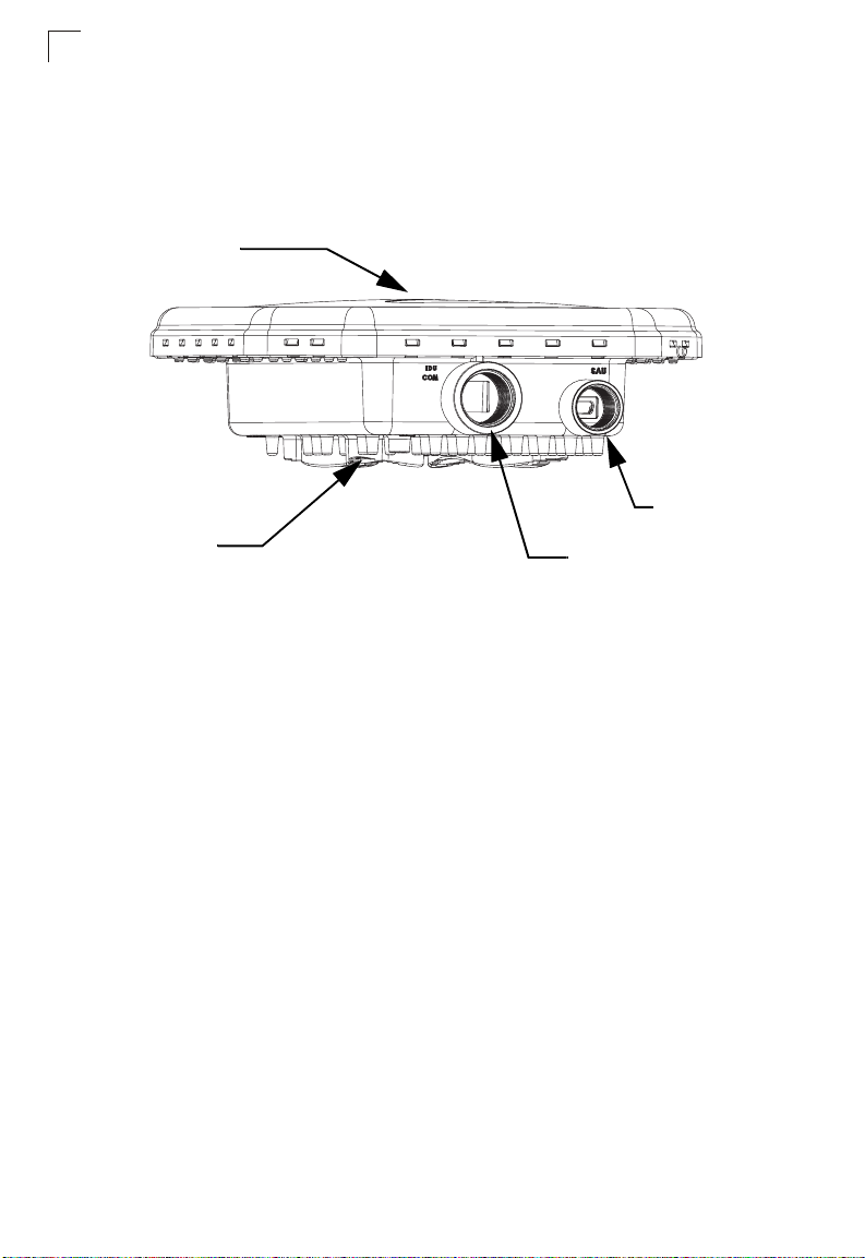
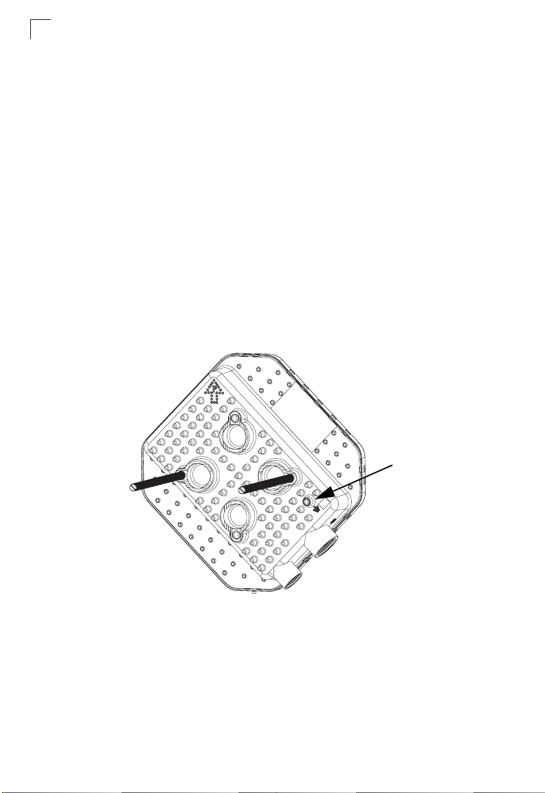
ODU Hardware Description
The ODU is an outdoor, pole-mounted, weatherproof unit that includes a built-in
antenna for WiMAX communications. The unit includes an RJ-45 Ethernet port for a
connection to the IDU.
Built-in Antenna
SAU Port
Ground Screw
Figure 1-1 ODU Components
Built-in WiMAX Antenna
One high-gain internal antenna is built into the ODU for WiMAX communications.
The antenna must be aligned towards the direction of the WiMAX service provider’s
base station.
RJ-45 PoE Port
RJ-45 PoE Port
The ODU has one 10BASE-T/100BASE-TX RJ-45 port that connects to the IDU
using Ethernet cable. The Ethernet port supports a Power over Ethernet (PoE)
connection to the IDU, delivering power from the IDU as well as a data link.
SAU Port
A Subscriber Unit Alignment Unit (SAU) port is included for connecting an optional
SAU device that provides indicator status LEDs for antenna alignment.
Weatherproof Port Covers
The ODU includes weatherproof port covers for the RJ-45 and SAU ports. The
RJ-45 port cover allows the Ethernet cable to be fed through and conneted to the
RJ-45 port. The SAU port cover protects the SAU port when it is not in use.
1-2
Page 19
ODU Hardware Description
Ground Screw
The ODU includes its own built-in lightning protection, however it is also important
that the unit is properly connected to ground. A grounding screw is provided for
attaching a ground wire to the unit.
Pole-Mounting Bracket Kit
The ODU includes a bracket kit that is used to mount the unit to a pole, radio mast,
or part of a tower structure.
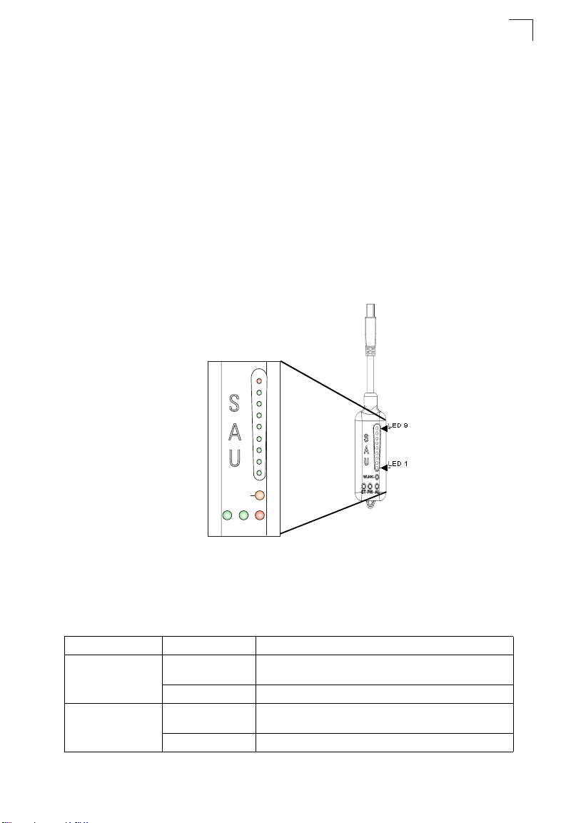
SAU (Optional)
The SAU device can be connected to the ODU during installation to assist with
antenna alignment and testing.
1
WLNK
ET PW AL
Figure 1-2 SAU LED Indicators
When connected to the ODU, the SAU provides status LED indications as described
in the following table.
Table 1-2 SAU LED Indicators
LED Status Description
AL (Alarm) Off The diagnostic test has passed and the ODU is operating
On Red An ODU failure has been detected.
PW (Power) Off The ODU is not receiving power or there is an internal
On Green The SAU is receiving power from the ODU.
normally.
3.3 VDC failure.
1-3
Page 20

Introduction
1
Table 1-2 SAU LED Indicators (Continued)
LED Status Description
ET (Ethernet) Off There is no valid Ethernet link between the ODU and the
On Green There is a valid Ethernet link between the ODU and the
WLNK
(Wireless link)
1 On Green 5dB ≤ SNR < 10dB
1-2 On Green 10dB ≤ SNR < 15dB
1-3 On Green 15dB ≤ SNR < 20dB
1-4 On Green 20dB ≤ SNR < 24dB
1-5 On Green SNR ≥ 24dB and RSSI < -75dBm
1-6 On Green SNR ≥ 24dB and RSSI ≥ -75dBm
1-7 On Green SNR ≥ 24dB and RSSI ≥ -70dBm
1-8 On Green SNR ≥ 24dB and RSSI ≥ -60dBm
1-9 1-8 On Green
1-8 in sequence Cycle On/Off
5, 4&6, 3&7, 2&8, 1
in sequence
Off The ODU is not connected to a base station.
On Orange The ODU is connected to and receives services from a
Blinking Orange Authentication has failed due to one of the following
9 On Red
Green
Cycle On/Off
Green
IDU.
IDU.
base station (Network Entry completed). Link quality is
indicated by LEDs 1-9, as described below.
reasons (indicated by the WiMAX Link LEDs):
• If LEDs 6, 7 and 8 are on: Authentication has been
rejected by the RADIUS server.
• If LEDS 7 and 8 are on: Authentication has been
rejected by the base station (due to a duplicate
subscriber unit name in its database).
• If LED 8 is on: Authentication has failed due to a
timeout, or there was a re-authentication failure
(connection to the RADIUS server was lost or a
mismatched shared secret).
RSSI ≥ -20dBm (saturation)
Indicates a full frequency scan in progress.
Selecting a detect ed base station with the strongest s ignal,
or a short scan.
1-4
Page 21

Chapter 2: Installing the OD200
This section describes how to install and connect the OD200 WiMAX Residential
Gateway.
Package Checklist
The OD200-ODU package includes:
• ODU outdoor WiMAX unit
(OD200-2.3-ODU, OD200-2.5-ODU, or OD200-3.5-ODU)
• ODU pole-mount bracket kit
Installation Overview
Before installing the OD200, verify that you have all the items listed in the package
checklist above. If any of the items are missing or damaged, contact your local
dealer. Also, be sure you have all the necessary tools and cabling before installing
the OD200.
Hardware installation of the OD200 involves these steps:
1. Mount the ODU on a pole, mast, or tower using the mounting bracket.
2. Install the IDU indoors.
3. Connect the ODU-IDU Ethernet cable and a grounding wire to the ODU.
4. Align the ODU antenna with the base station.
2-1
Page 22

Installing the OD200
2
ODU Installation
The ODU includes its own bracket kit for mounting the unit to a 1 to 4 inch diameter
steel pole or tube. The pole-mounting bracket allows the unit to be mounted to part
of a radio mast or tower structure.
Caution: The planning and installation of the ODU requires professional personnel
that are trained in the installation of radio transmitting equipment. The user
is responsible for compliance with local regulations concerning items such
as building safety codes, use of lightning arrestors, and grounding.
Therefore, you must consult a professional contractor knowledgeable in
local regulations prior to equipment installation.
ODU Location
The ODU should be installed outdoors, mounted to a pole using the included
mounting bracket. When selecting an suitable location for the unit, consider these
guidelines:
• The ODU should be installed where it can provide a direct, or near line of sight with
the WiMAX base station. Normally, the higher the unit placement, the better the link
quality.
• Make sure there are no other radio antennas within 2 m (6 ft) of the ODU.
• Place the ODU away from power and telephone lines.
• Avoid placing the ODU too close to any metallic, refective surfaces, such as
roof-installed air-conditioning equipment, wire fences, or water pipes.
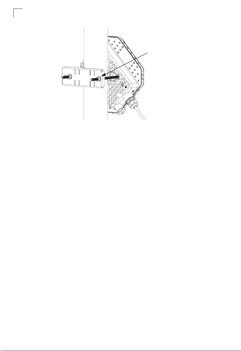
Mount the Unit
The ODU’s pole-mounting bracket attaches directly to the ODU using two long
threaded bolts. The bracket has V-shaped edges on one side that clamp the unit to a
pole. The bracket allows the ODU to be mounted to a pole in one of two orientations.
Perform the following steps to mount the unit to a 1 to 4 inch diameter steel pole or
tube using the mounting bracket:
1. Attach the two threaded bolts to the back of the ODU using a flat screwdriver.
Make sure you use the correct threaded holes for the required orientation.
Note: The ODU contains dual polarization antennas so it can be mounted in either
orientation. Note that the ODU connectors always face downward.
2-2
Page 23
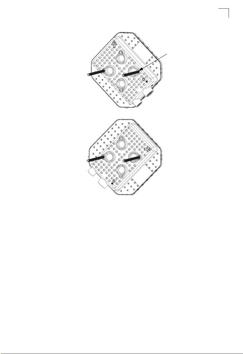
Orientation 1
Orientation 2
ODU Installation
Attach the two threaded
bolts to the ODU using a
flat screwdriver
2
Figure 2-1 ODU Orientations
2. Place the ODU against one side of the pole and then fit the bracket onto the
threaded bolts. The bracket’s V-shaped edges should be against the pole.
3. Use the included nuts and washers to secure the ODU to the pole. The
securing nuts should be just tight enough to hold the ODU to the pole. (The
bracket may need to be rotated around the pole during the antenna alignment
process.)
2-3
Page 24
Installing the OD200
2
Tighten the nuts to secure
the ODU to the pole
Figure 2-2 Securing the ODU to the Pole
ODU Cable Connections
The ODU needs to be connected to the IDU using Ethernet cable, and the ODU
must be grounded by connecting a grounding wire.
ODU-IDU Ethernet Cable Connection
Use outdoor-rated Category 5E or better Ethernet cable with RJ-45 connectors on
each end. Before connecting the cable, first plan a cable route from the ODU
outdoors to the IDU indoors. Consider these guidelines:
• Make sure the cable length does not exceed 100 meters (328 ft).
• Determine a building entry point for the cable.
• Determine if conduits, bracing, or other structures are required for safety or
protection of the cable.
• Be sure to ground the outdoor-rated Ethernet cable immediately before it enters
the building. See “Grounding the ODU-IDU Ethernet Cable” on page 2-5.
• For additional lightning protection, it is recommended to use a lightning arrestor
immediately before the Ethernet cable enters the building.
Caution: DC VOLTAGE! Do not connect the ODU port to a computer’s RJ-45 port.
To connect the ODU-IDU Ethernet cable, follow these steps:
1. Remove the cover from the IDU COM port on the ODU.
2. Cut the Ethernet cable to the required length and feed it through the port cover.
Then use a crimp tool to attach an RJ-45 connector to the Ethernet cable.
2-4
Page 25

ODU Cable Connections
Make sure the Ethernet twisted-pair wires are attached to the RJ-45 connector
following standard pin assignments. See “Twisted-Pair Cable Assignments” on
page C-1.
3. Connect the Ethernet cable to the IDU COM RJ-45 connector.
4. Screw the port cover back into the unit and tighten it to ensure protection
against moisture.
5. Seal the IDU COM connector using tar seal or weatherproof tape to protect
against rain and moisture.
6. Route the Ethernet cable from the ODU to the IDU following your cable plan
and connect it to the ODU port on the IDU. The RJ-45 port LED on the IDU
should turn on to indicate a valid link.
Note: Connecting the Ethernet cable to the IDU powers on the ODU.
Grounding the ODU-IDU Ethernet Cable
To comply with safety regulations, the shield of the ODU-IDU outdoor-rated Ethernet
cable must be connected to protective ground (earth). The grounding point can be
either inside the building, or immediately at the entry point to the building, depending
on where a protective ground is available.
Caution: Grounding the ODU-IDU Ethernet cable must be performed by a
professional installer in conformance with local safety regulations.
This document proposes one method for grounding the outdoor-rated Category 5E
Ethernet cable through its drain wire. The actual connection method employed is left
to the professional installer.
To ground the ODU-IDU Ethernet cable, follow these steps:
1. Strip back about a one inch (2.4 cm) section of the Ethernet cable jacket to
expose the drain wire.
2
Drain Wire
Figure 2-3 ODU-IDU Ethernet Cable Drain Wire
2. Attach a grounding cable to the drain wire and then connect it to protective
earth.
2-5
Page 26
Installing the OD200
2
3. Use weatherproof tape to cover and seal the attachment area on the Ethernet
cable.
Ground Wire Connection
When connecting a ground wire to the ODU, use the grounding screw located on the
base of the unit. Be sure to use #14 AWG or larger copper core ground wire.
Caution: Be sure that grounding is available and that it meets local and national
electrical codes. Grounding the ODU must be performed by a professional
installer.
The ground wire can be connected to a point on the bracket, pole, metal grounding
plate, or directly to an earth termination. Make sure that there is a good electrical
connection between the ground wire and the grounding point (no paint or isolating
surface treatment).
To connect a grounding wire to the ODU, follow these steps:
1. Crimp a ring lug onto the end of the ground wire before connecting it to the unit.
2. Place the ground wire lug on the grounding point and firmly tighten the screw.
Ground Screw
Figure 2-4 ODU Grounding Screw
3. Connect the other end of the grounding wire to a good ground (earth)
connection.
Note: Use cable strips to secure all cables to the pole.
2-6
Page 27
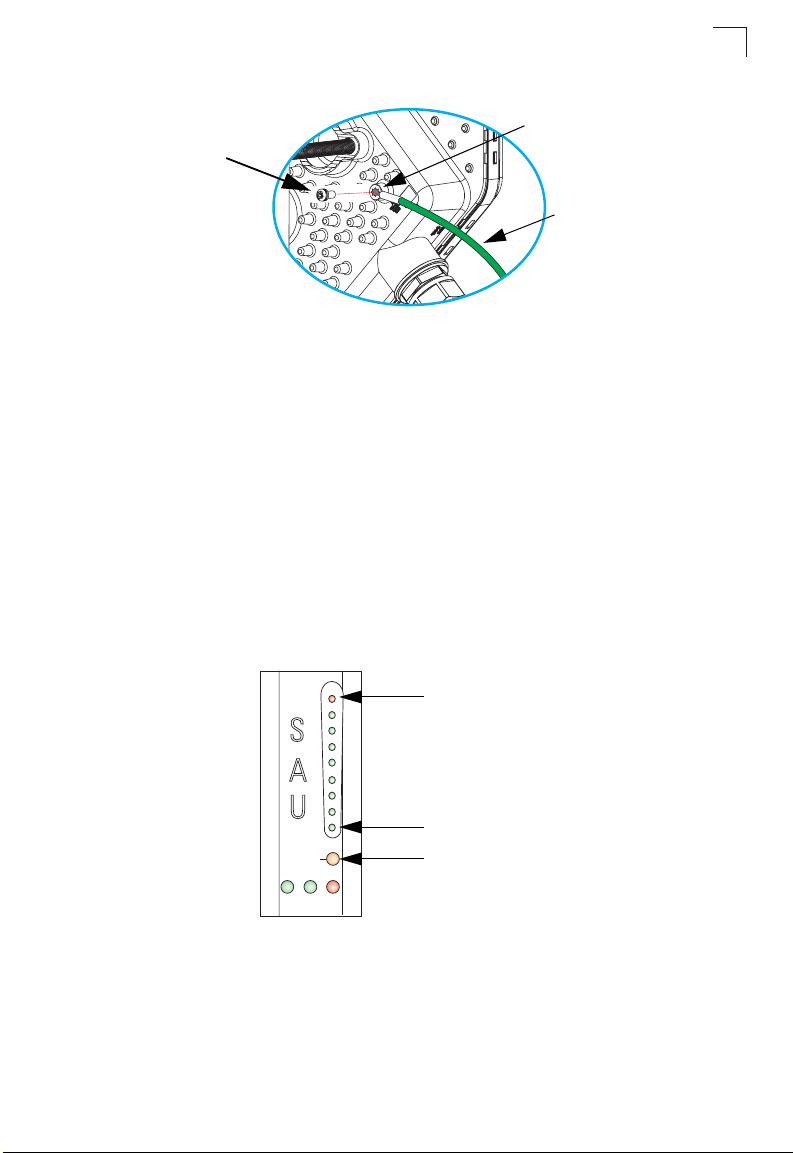
ODU Antenna Alignment
Ring Lug
Ground Screw
Ground Wire
Figure 2-5 Ground Wire Connection
ODU Antenna Alignment
The ODU will provide the best link quality when its antenna is aligned in the direction
of the WiMAX base station. The optional SAU can be connected to the ODU to
provide status LED indications and assist with antenna alignment.
To align the ODU antenna using the SAU, follow these steps:
1. Remove the cover from the SAU port on the ODU.
2. Connect the SAU device to the SAU port. The PW (power) LED should turn on
to indicate that it is properly connected.
3. Point the ODU antenna in the general direction of the base station, then pan the
ODU back and forth while watching the link quality LEDs (see Table 1-2).
2
LED 9
LED 1
WLNK
ET PW AL
Figure 2-6 SAU LED Indicators
4. Find the point where the link quality is best and secure the ODU in that position.
Verify that the SAU’s WLNK LED is on, indicating that the unit is synchronized
with the base station.
Note: If all the SAU link quality LEDs are on, including LED 9 (red), the received signal
strength is too high. Move the ODU’s position so that only LEDs 1 to 8 are on.
Network Entry Complete
2-7
Page 28
Installing the OD200
2
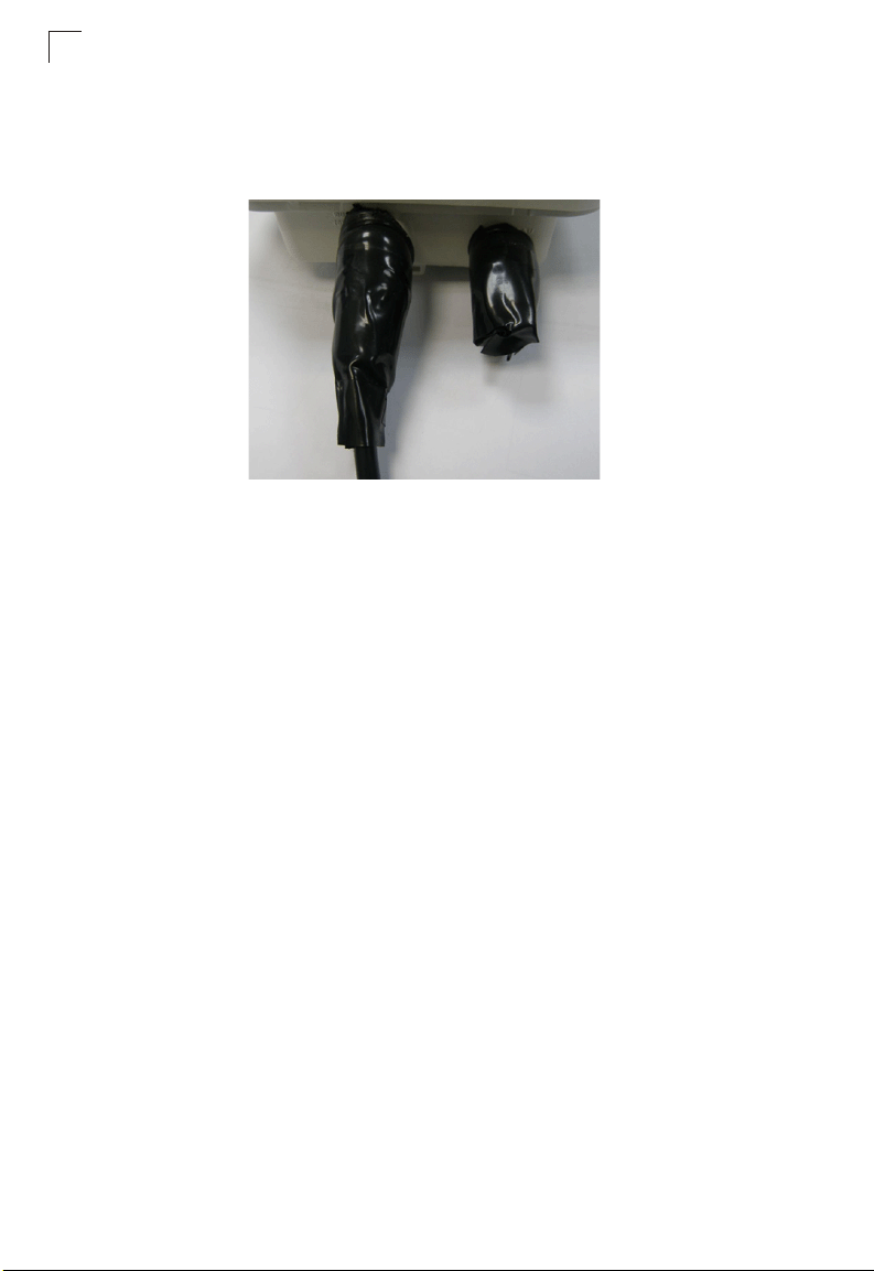
5. Remove the SAU connection and replace the cover on the port.
6. Seal the SAU connector using tar seal or weatherproof tape to protect against
rain and moisture.
Figure 2-7 Sealed ODU Connectors
2-8
Page 29
Chapter 3: Initial Configuration
The OD200 can be configured through its web management interface. The web
interface provides a simple Basic Setup or Advanced Setup options.
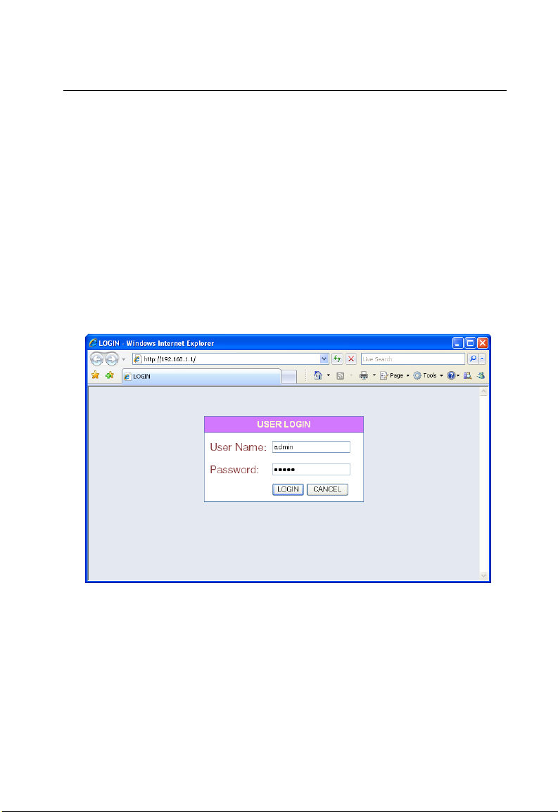
Accessing the Web Management Interface
The OD200 has a default IP address of 192.168.1.1 and a subnet mask of
255.255.255.0. If your PC is set to have an IP address assigned by DHCP (Dynamic
Host Configuration Protocol), you can connect immediately to the web management
interface. Otherwise, you must first check if your PC’s IP address is set on the same
subnet as the OD200 (that is, the PC’s IP address starts 192.168.1.x).
In the web browser’s address bar, type the default IP address: http://192.168.1.1.
The web browser displays the OD200’s login page.
Figure 3-1 Login Page
Logging In – Type the default User Name “admin” and Password “admin,” then click
Login. The home page displays.
3-1
Page 30
Initial Configuration
3
Figure 3-2 Home Page
To configure basic settings for the current operating mode, click Basic Setup. For
more information, see “Initial Configuration” on page 3-1.
Alternatively, to configure more detailed settings, click Advanced Setup. For more
information, see “The Advanced Setup Menu” on page 3-5.
Note: It is recommended that you configure a user password as the first step under
“Administrator Settings” on page 4-3 to control management access to the
3-2
unit.
Page 31

Using the Basic Setup
Using the Basic Setup
The Basic Setup takes you through the basic configuration steps for the OD200.
Launching the Basic Setup – To perform basic configuration, click Basic Setup on
the home page.
When configuring the unit through the Basic Setup you will need to proceed through
the following steps:
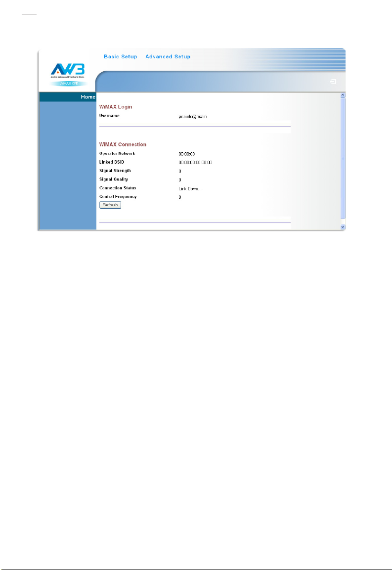
1. WiMAX Login – Configures user authentication settings for connection to the
WiMAX network.
3
Figure 3-3 WiMAX Login
User Name – The user name required for authentication as provided by the
WiMAX operator. (Default: pseudo@realm)
Password – The user password required for authentication as provided by the
WiMAX operator. (Default: hello)
3-3
Page 32

Initial Configuration
3
2. Apply Settings – Click “Apply” to confirm the basic settings.
Figure 3-4 Apply Settings
3. Basic Setup Finished – When the Basic Setup steps are completed the unit
reboots and attempts to connect to the specified WiMAX network. Click on the
Home button to return to the Home page.
3-4
Figure 3-5 Basic Setup Finished
Page 33

The Advanced Setup Menu
The Advanced Setup Menu
The Advanced Setup menu provides access to all the configuration settings
available for the OD200.
Figure 3-6 Advanced Setup
3
Each primary menu item is sumarized below with links to the relevant section in this
guide where configuration parameters are described in detail:
• System – Configures general device settings. see page 4-1
• WAN – Configures WAN settings. see page 5-2
• LAN – Configures LAN settings. see page 5-8
• NAT – Configures Network Address Translation settings. see page 5-9
• Firewall – Configures firewall settings. see page 5-12
• Route – Configures static routing settings. see page 5-16
• UPnP – Enables UPnP. see page 5-17
• WiMAX – Views the wireless connection status. see page 6-1
• VoIP – Configures VoIP SIP settings. see page 7-1
• WiFi – Configures 802.11 access point settings. see page 8-1
3-5
Page 34

Initial Configuration
3
3-6
Page 35

Chapter 4: System Settings
The gateway’s System menu allows you to perform general management functions
for the unit, including setting the system time, configuring an access password, and
upgrading the system software.
The System pages include the following options.
Table 4-1 System Settings
Menu Description Page
Host Name Config Configures a host name and domain name 4-1
System Status Displays WAN and LAN interface information and other system
Administrator Settings Configures user password for management
Firmware Upgrade Updates the current firmware 4-4
Configuration Tools Restores the factory default settings, or save the unit’s current
System Time Configures the system time settings for updates from a time server 4-6
System Log Displays event log entries 4-7
Reset Resets the device 4-8
details
access
settings
Host Name
4-2
4-3
4-4
The gateway allows you to define a name that identifies your unit and the domain
name used by the local network. Setting a host name enables the web interface to
be accessed using an easy-to-remember name instead of its IP address.
Figure 4-1 System Host Name
•Host Name – Enter the name chosen for the unit. (Default: cpe)
• Domain Name – Enter the domain to which the unit is connected.
4-1
Page 36

System Settings
4
System Status
The system status page displays connectivity status information for the unit’s
WiMAX (WAN) and LAN interfaces, firmware and hardware version numbers, and
the number of clients connected to your network.
Figure 4-2 System Status – Internet
INTERNET – Displays WAN (WiMAX) connection status:
• WAN IP – Displays the IP address assigned by the service provider.
• Subnet Mask – Displays the WAN subnet mask assigned by the service provider.
• Gateway – Displays the WAN gateway address assigned by the service provider.
• Primary DNS – Displays the WAN primary Domain Name System server address.
• Secondary DNS – Displays the WAN secondary Domain Name System server
address.
• Connection Type – Displays the connection type for the WAN. Either FIXED for a
static IP setting, or DHCPC for dynamic IP assignment.
Figure 4-3 System Status – Gateway
GATEWAY – Display system IP settings, as well as DHCP, NAT and firewall status:
• IP Address – Displays the unit’s IP address.
• Subnet Mask – Displays the subnet mask.
4-2
Page 37

Administrator Settings
• DHCP Server – Displays the DHCP server status.
• Firewall – Displays the firewall status.
Figure 4-4 System Status – Information
INFORMATION – Displays the number of connected clients, as well as the unit’s
LAN and WAN MAC addresses:
• Connected Clients – Displays the number of connected clients, if any.
• Runtime Code Version – Displays the runtime code version.
• LAN MAC Address – Displays the LAN MAC address.
• WAN MAC Address – Displays WAN MAC address.
Administrator Settings
The Administrator Settings page enables you to change the default password for
management access to the gateway.
4
Figure 4-5 Setting a Password
Current Password – You need to first enter your current administrator password to
be able to configure a new one. (Default: admin)
New Password – Enter a new administrator password. (Range: 3~12 characters)
4-3
Page 38

System Settings
4
Confirm New Password – Enter the new password again for verification.
(Range: 3~12 characters)
Auto-Logout Time – The time of inactivity after which the unit terminates a web
management session. (Default: 30 minutes; Range: 1~99 minutes)
NMS IP Address – The IP address of a network management station on the
operator’s network. The unit will send SNMP trap messages to a management
station when the operator’s DHCP server does not return an IP address to the
gateway.
Firmware Update
The Firmware Update page enables you to download new software to the unit.
Figure 4-6 Firmware Update
Firmware Update – Downloads an operation code file from the web management
station to the gateway using HTTP. Use the Browse button to locate the code file
locally on the management station and click Apply to proceed.
Configuration Tools
The Configurations Tools page allows you to restore factory default settings, or save
and restore the unit’s configuration settings to or from a file on the management
station.
Figure 4-7 Configuration Tools
4-4
Page 39

Configuration Tools
Restore Factory Default Configuration – Resets the unit to its factory default
settings.
Backup Settings/Restore Settings – When selected, prompts either to backup the
current configuration to a file, or select a previously backed up file to restore to the
unit.
When you select “Restore Factory Default Configuration” and click Apply, a
confirmation page displays. Click the Restore button to continue.
Figure 4-8 Restore Factory Default Configuration
When you select “Backup Settings/Restore Settings” and click Apply, The following
page displays.
4
Figure 4-9 Backup/Restore Settings
Backup Settings – Saves the current configuration settings to a file named
“config.bin” on the web management station.
Restore Settings – Restores a saved configuration file to the unit. You can use the
Browse button to locate the file on the web management station.
4-5
Page 40

System Settings
4
System Time
The gateway uses the Simple Network Time Protocol (SNTP) to set its internal clock
based on periodic updates from a time server. Maintaining an accurate time on the
device enables the system log to record meaningful dates and times for event
entries.
SNTP uses Coordinated Universal Time (or UTC, formerly Greenwich Mean Time,
or GMT) based on the time at the Earth’s prime meridian, zero degrees longitude. To
display a time corresponding to your local time, you must select your time zone.
Figure 4-10 System Time
Time Protocol – Select SNTP to enable the unit to set its internal clock based on
periodic updates from a time server. The unit acts as an SNTP client, periodically
sending time synchronization requests to a specified time server. Alternatively, you
can select “None” and set the time and date manually. (Default: SNTP)
Time Server Address – The IP address of a time server that the unit attempts to
poll for a time update. (Default: 192.43.244.18)
Current Time (hh:mm:ss) – Displays the current time of the system clock.
New TIme (hh:mm:ss) – Sets the system clock to the time specified.
Current Date (yyyy:mm:dd) – Displays the current date of the system clock.
New Date (yyyy:mm:dd) – Sets the system clock to the date specified.
Set Time Zone – SNTP uses Coordinated Universal Time (or UTC, formerly
Greenwich Mean Time, or GMT) based on the time at the Earth’s prime meridian,
zero degrees longitude. To display a time corresponding to your local time, you must
select your time zone from the pull-down list. (Default: (GMT+08:00) Taipei)
4-6
Page 41

System Log
System Log
The System Log page allows you to display system event messages. The logged
messages can serve as a valuable tool for isolating device and network problems,
and also indicate if any unauthorized attempts have been made to gain access to
your network.
4
Figure 4-11 System Log
Syslog Level – Sets the minimum severity level for event logging. The system
allows you to limit the messages that are logged by specifying a minimum severity
level. Error message levels range from the most severe (Emergency) to least severe
(Debug). The message levels that are logged include the specified minimum level
up to the Emergency level. (Default: Info)
Download – Downloads the current log file to the web management station.
Clear – Deletes all entries in the current log file.
Refresh – Updates the displayed log entries on the web page.
Note: Log messages saved in the unit’s memory are erased when the device is
rebooted.
4-7
Page 42

System Settings
4
Reset
The Reset page allows you to restart the device’s software. If the unit stops
responding correctly or in some way stops functioning, performing a reset can clear
the condition.
Figure 4-12 Reset Unit
Reset – Resets the unit. All current settings are retained.
4-8
Page 43

Chapter 5: Gateway Configuration
The information in this chapter covers the configuration options for the OD200’s
Internet gateway functions.
The OD200 provides comprehensive firewall features and NAT isolation for Internet
traffic passing from the WiMAX service provider to the local network connected to
the LAN ports. The DHCP server feature can assign IP addresses for up to 32 local
network PCs and wireless clients.
The Advanced Setup menu includes the following items for Internet gateway
configuration.
Table 5-1 Gateway Configuration
Menu Description Page
WAN 5-2
WAN Settings Sets the connection method of your Internet service provider 5-2
DNS Specifies DNS servers that you want to access 5-6
SNMP IP Setting Sets SNMP management IP filters 5-7
LAN 5-8
LAN Settings Sets the unit’s IP address and configures the DHCP server
for the local network
DHCP Client List Displays connected DHCP clients that have been assigned
IP addresses by the DHCP server
NAT 5-9
Virtual Server Allows the unit to be configured as a virtual server 5-9
Port Mapping Enables IP port mapping for special applications 5-11
DMZ Allows clients to connect to the unit directly bypassing the
firewall
Firewall 5-12
Firewall Setting Controls access to and from the local network 5-12
Firewall Options Blocks scans of the network services from an outside hacker 5-12
Client Filtering Blocks Internet access based on IP addresses 5-14
MAC Control Blocks internet access based on MAC addresses 5-15
Route 5-16
Routing Table List Displays the routing table 5-16
UPnP 5-17
Settings Provides support for Universal Plug and Play devices 5-17
5-8
5-9
5-12
5-1
Page 44

Gateway Configuration
5
WAN Settings
Select the WAN connection type used by your service provider and specify DNS
(Domain Name System) servers.
Figure 5-1 WAN Settings
The unit can be connected to your ISP in one of the following ways:
Dynamic IP Address – Selects configuration for an Internet connection using
DHCP for IP address assignment. This is the default setting.
Static IP Address – Selects configuration for an Internet connection using a fixed IP
assignment.
L2TP – Selects configuration for an Internet connection using the Layer 2 Tunneling
Protocol, an access protocol often used for virtual private networks.
PPPoE – Selects configuration for an Internet connection using the Point-to-Point
Protocol over Ethernet (PPPoE), a common connection method used for DSL
access.
Note: For the Dynamic IP Address (DHCP) option, the unit requires no further
configuration. Selecting other WAN types displays the parameters that are
required for configuring the connection.
5-2
Page 45

WAN Settings
Dynamic IP Address
For dynamic IP assignment from the service provider, the unit functions as a
Dynamic Host Configuration Protocol (DHCP) client. When enabled, no other
settings are required.
Figure 5-2 Dynamic IP Address
Static IP Settings
Selecting Static IP Address for the WAN type enables you to enter static IP settings
as assigned by the service provider.
5
Figure 5-3 Static IP Settings
IP Address assigned by your ISP – The IP address provided by your service
provider. Valid IP addresses consist of four decimal numbers, 0 to 255, separated by
periods.
Subnet Mask – Indicates the subnet mask, such as 255.255.255.0.
Gateway – The gateway IP address provided by your service provider.
5-3
Page 46

Gateway Configuration
5
L2TP Settings
If your service provider supports Layer 2 Tunneling Protocol (L2TP) for your Internet
connection, configure the settings described below.
Figure 5-4 L2TP Settings
User Name – Enter your user name for connecting to the L2TP service, as supplied
by the service provider. (Range: 1-32 characters)
Password – Specify the password for your connection, as supplied by the service
provider. (Default: No password)
L2TP Network Server – The IP address of the L2TP server, as specified by the
service provider.
Keep Alive – This option enables the unit to check periodically that the L2TP
connection is still operating. If the connection is found to be lost, the unit
automatically attempts to reconnect to the service provider. (Default: Enabled)
Keep Alive Time – The time period the unit waits before checking that the L2TP
connection is still operating. This parameter only applies when Keep Alive is
enabled. (Default: 60 seconds; Range: 10-180 seconds)
5-4
Page 47

WAN Settings
PPPoE Settings
If your service provider supports Point-to-Point Protocol over Ethernet (PPPoE) for
your Internet connection, configure the settings described below.
Figure 5-5 PPPoE Settings
PPPoE Network Server – The IP address of the PPPoE server, as specified by the
service provider.
5
Keep Alive – This option enables the unit to check periodically that the PPPoE
connection is still operating. If the connection is found to be lost, the unit
automatically attempts to reconnect to the service provider. (Default: Enabled)
Keep Alive Time – The time period the unit waits before checking that the PPPoE
connection is still operating. This parameter only applies when Keep Alive is
enabled. (Default: 60 seconds; Range: 10-180 seconds)
5-5
Page 48

Gateway Configuration
5
DNS
DNS (Domain Name System) server addresses are usually provided by service
providers, however if you want to specify certain servers, the DNS page enables you
to enter primary and secodary DNS addresses.
Figure 5-6 DNS Settings
Domain Name Server (DNS) Address – Address of the primary DNS server,
specified in the form of 0.0.0.0. (The default address 0.0.0.0 disables the manual
DNS setting.)
Secondary DNS Address (optional) – Optional address of a secondary DNS
server, specified in the form of 0.0.0.0.
5-6
Page 49

WAN Settings
SNMP IP Setting
Simple Network Management Protocol (SNMP) is a communication protocol
designed specifically for managing devices on a network. SNMP is typically used to
configure devices for proper operation in a network environment, as well as to
monitor them to evaluate performance or detect potential problems.
The gateway includes an agent that supports SNMP version 1 and 2c access. A
network management station can access the gateway using SNMP management
software. To implement SNMP management, the gateway must first have an
assigned IP address and subnet mask.
Access to the gateway using SNMP v1 and v2c is controlled by community strings.
To communicate with the gateway, the management station must first submit a valid
community string for authentication. In addition, the SNMP management station IP
must be configured on the gateway to permit SNMP access.
The default community strings for the gateway are “public” for read-only access, and
“private” for read/write access. The default community strings can be changed only
through SNMP management software.
5
Figure 5-7 SNMP IP Setting
SNMP Allowed IP – The list of management station IPs that are permitted SNMP
access to the gateway. Up to five IP addresses can be configured for management
access. Check the Enabled checkbox to enable a configured IP address.
5-7
Page 50

Gateway Configuration
5
LAN
The OD200 must have a valid IP address for management using a web browser and
to support other features. The unit has a default IP address of 192.168.1.1. You can
use this IP address or assign another address that is compatible with your existing
local network. The unit can also be enabled as a Dynamic Host Configuration
Protocol (DHCP) server to allocate IP addresses to local PCs.
LAN Settings
The OD200 includes a DHCP server that can assign temporary IP addresses to any
attached host requesting the service. Addresses are assigned to clients from a
common address pool configured on the unit. Configure an address pool by
specifying start and end IP addresses. Be sure not to include the unit's IP address in
the address pool range.
Figure 5-8 LAN Settings
IP Address – The IP address of the unit. Valid IP addresses consist of four decimal
numbers, 0 to 255, separated by periods.The default setting is 192.168.1.1.
Subnet Mask – Indicates the local subnet mask is fixed as 255.255.255.0.
The Gateway acts as DHCP Server – Check this box to enable the DHCP server.
IP Pool Starting/Ending Address – Specifies the start and end IP address of a
range that the DHCP server can allocate to DHCP clients. You can specify a single
address or an address range. Note that the address pool range is always in the
same subnet as the unit’s IP setting. (Default: 192.168.1.2 to 192.168.1.254)
5-8
Page 51

NAT
Lease Time – Selects a time limit for the use of an IP address form the IP pool.
When the time limit expires, the client has to request a new IP address.
(Default: Half hour; Options: Half hour, one hour, two hours, half day, one day,
two days, one week, two weeks)
Local Domain Name – This optional parameter specifies the name of the domain
the unit is attached to.
DHCP Client List
The DHCP Client List page enables you to see the MAC address of devices that are
currently connected to the unit and have been assigned an IP address by the DHCP
server.
Figure 5-9 DHCP Client List
NAT
5
Network Address Translation (NAT) is a standard method of mapping multiple
"internal" IP addresses to one "external" IP address on devices at the edge of a
network. For the OD200, the internal (local) IP addresses are the IP addresses
assigned to local PCs by the DHCP server, and the external IP address is the IP
address assigned to the WiMAX interface.
Virtual Server
Using the NAT Virtual Server feature, remote users can access different servers on
your local network using your single public IP address.
Remote users accessing services such as web or FTP at your local site thorugh
your public IP address, are redirected (mapped) to other local server IP addresses
and TCP/UDP port numbers. For example, if you set Type/Public Port to TCP/80
(HTTP or web) and the Private IP/Port to 192.168.7.9/80, then all HTTP requests
from outside users forwarded to 192.168.7.9 on port 80. Therefore, by just using
your external IP address provided by your ISP, Internet users can access the
services they need at the local addresses to which you redirect them.
5-9
Page 52

Gateway Configuration
5
The more common TCP service port numbers include: HTTP: 80, FTP: 21, Telnet:
23, and POP3: 110.
Figure 5-10 Virtual Server
Private IP – The IP address of the server on the local Ethernet network. The
specified address must be in the same subnet as the OD200 and its DHCP server
address pool. (Range: 192.168.1.1 to 192.168.1.254)
Private Port – Specifies the TCP/UDP port number used on the local server for the
service. (Range: 0-65535)
Typ e – Specifies the port type. (Options: TCP or UDP; Default: TCP)
Public Port – Specifies the public TCP/UDP port used for the service on the WAN
interface. (Range: 0-65535)
Enabled – Enables the virtual server mapping on the specified ports.
(Default: Disabled)
5-10
Page 53

NAT
Port Mapping
Some applications, such as Internet gaming, videoconferencing, Internet telephony
and others, require multiple connections. These applications cannot work with
Network Address Translation (NAT) enabled. If you need to run applications that
require multiple connections, use port mapping to specify the additional public ports
to be opened for each application.
Figure 5-11 Port Mapping
Server IP – The IP address of the local server. (Range: 192.168.1.1 to
192.168.1.254)
5
Mapping Ports – Specifies the TCP/UDP ports that the application requires. The
ports may be specified individually, in a range, or a combination of both. For
example, 7, 11, 57, 72-96. (Range: 0-65535)
Enabled – Enables port mapping for the specified IP address. (Default: Disabled)
5-11
Page 54

Gateway Configuration
5
DMZ
If you have a client PC that cannot run an Internet application properly from behind
the NAT firewall, you can open the client up to unrestricted two-way internet access
by defining a virtual-DMZ (virtual-demilitarized-zone) host.
Figure 5-12 DMZ Settings
Enable – Enables the feature. (Default: Disabled)
IP Address of Virtual DMZ Host – Specifies the IP address of the virtual DMZ host.
(Range: 192.168.1.1 to 192.168.1.254; Default: 0.0.0.0)
Note: Adding a host to the DMZ may expose your local network to a variety of security
risks, so only use this option as a last resort.
Firewall
The OD200 provides extensive firewall protection by restricting connection
parameters to limit the risk of intrusion and defending against a wide array of
common hacker attacks. You can also block access to the Internet from clients on
the local network based on IP addresses and TCP/UDP port numbers, or specific
MAC addresses.
Figure 5-13 Firewall Setting
Enable – Enables the feature.
Disable – Disables the feature. (This is the default.)
5-12
Page 55

Firewall
Firewall Options
The OD200’s firewall enables access control of client PCs, blocks common hacker
attacks, including IP Spoofing, Land Attack, Ping of Death, Smurf Attack, TCP null
scan, ICMP defect, and TCP SYN flooding. The firewall does not significantly affect
system performance and it is best to leave it enabled to protect your network.
Figure 5-14 Firewall Options
Enable Hacker Attack Protect – Network attacks that deny access to a network
device are called DoS attacks. DoS attacks are aimed at devices and networks with
a connection to the Internet. Their goal is not to steal information, but to disable a
device or network so users no longer have access to network resources. The Router
protects against the following DoS attacks: IP Spoofing, Land Attack, Ping of Death,
Smurf Attack, TCP null scan, ICMP defect, and TCP SYN flooding.
5
Discard PING from WAN side – Prevents pings on the unit’s WiMAX interface from
being routed to the network.
Discard to PING the Gateway – Prevents any response to a ping to the unit’s IP
address.
Drop Port Scan – Prevents outside hackers form testing the TCP/UDP port
numbers on the unit for any services.
5-13
Page 56

Gateway Configuration
5
Client Filtering
You can block access to the Internet from clients on the local network by specifying
IP addresses and TCP/UDP port numbers. You can configure up to five IP filters on
the unit.
Figure 5-15 Client Filtering Settings
Enable Client Filter – Enables client filtering for entries in the table.
(Default: Disabled)
IP – Specifies an IP address or range on the local network. (Range: 192.168.1.1 to
192.168.1.254)
Port – Specifies a TCP/UDP port number range to filter. (Range: 0-65535)
Typ e – Specifies the the port type. (Options: TCP or UDP; Default: TCP)
Enable – Enables filtering for the table entry. (Default: Disabled)
5-14
Page 57

Firewall
MAC Control
You can block access to the Internet from clients on the local network by MAC
addresses. You can configure up to 32 MAC address filters on the unit.
Figure 5-16 MAC Control
MAC Address Control – Enables the feature. (Default: Enabled)
Block Connect to Internet – Blocks Internet access for the scpecified MAC
address. (Default: Enabled)
5
MAC Address – Specifies a local PC MAC address.
Add – Adds a new MAC address to the filter table.
Delete – Removes a MAC address from the filter table.
5-15
Page 58

Gateway Configuration
5
Route
The
Routing Table displays the list of static routes on the unit.
Figure 5-17 Routing Table
Destination LAN IP – The IP address that identifies the IP subnet of the remote
network.
Subnet Mask – The mask that identifies the IP subnet of the remote network.
Gateway – The IP address of the router within the local IP subnet that forwards
traffic to the remote IP subnet.
Metric – Cost for the local interface. This cost is only used when routes are imported
by a dynamic routing protocol.
Interface – Indicates the local network interface on the unit.
5-16
Page 59

UPnP
UPnP
UPnP (Universal Plug and Play Forum) provides inter-connectivity between devices
supported by the same standard.
Figure 5-18 UPnP Setting
UPnP – Enables UpnP support on the unit. (Default: Enabled)
5
5-17
Page 60

Gateway Configuration
5
5-18
Page 61

Chapter 6: WiMAX Settings
The OD200’s WiMAX menu enables you to configure WiMAX connection profiles,
view subscriber station information, and select an operating antenna.
The WiMAX pages include the following options.
Table 6-1 WiMAX Settings
Menu Description Page
Profile Configures WiMAX connection profiles 6-1
SSinfo Displays subscriber station information for the unit 6-4
Antenna Setting Configures use of internal or external antennas 6-5
Advance Configure Configures extended WiMAX features 6-6
Profile Configuration
A profile allows a user to set specific details for connecting to various WiMAX
service providers. The OD200 must have at least one profile configured to be able to
connect to a WiMAX service.
Figure 6-1 WiMAX Profile Configuration
Operator ID – The ID number that identifies the WiMAX operator for this profile.
(Default: 00:00:02)
6-1
Page 62

WiMAX Settings
6
Operator name – The WiMAX operator name. (Default: AWB)
Operator Restriction – When enabled, the user can only connect to the service
provider specified in the profile. The user cannot roam to other networks. When
disabled, the operator specified in the profile will be used when base stations are
detected, otherwise the user can roam to other networks. (Default: Disabled)
Scan Frequency – Specifies a center frequency to scan. (Range: 2000-4000 MHz)
Scan Bandwidth – Specifies the bandwidth of the scan channel. (Options: 5.00,
7.00, 8.75, 10.00 MHz; Default: 10.00 MHz)
Add/Remove – Use the Add button to add a new center frequency and channel
bandwidth to scan. Use the Remove button to delete a frequency from the scan list.
Authentication
Set user authentication for the WiMAX connection profile, as specified by the service
provider. Selecting EAP-TLS, EAP-TTLS-CHAP, or EAP-TTLS-MSCHAPV2 displays
the parameters that are required for configuring the authentication method.
6-2
Figure 6-2 WiMAX Profile Authentication - EAP-TLS
Figure 6-3 WiMAX Profile Authentication - EAP-TTLS-CHAP
Page 63

Profile Configuration
Figure 6-4 WiMAX Profile Authentication - EAP-TTLS-MSCHAPV2
Enable Authentication – Enables user authentication for connection to the
network. (Default: Disabled)
EAP Method – Selects the Extensible Authentication Protocol (EAP) method to use
for authentication. (Default: EAP-TTLS-MSCHAPV2)
• EAP-TLS – Transport Layer Security. Provides for certificate-based and mutual
authentication of the client and the network. It relies on client-side and server-side
certificates to perform authentication and can be used to dynamically generate
user-based and session-based encryption keys to secure subsequent
communications between the user and the network. A unique X.509 authentication
certificate is included with the gateway firmware.
• EAP-TTLS-CHAP – Tunneled Transport Layer Security with
Challenge-Handshake Authentication Protocol (CHAP). This security method
provides for certificate-based, mutual authentication of the client and network
through an encrypted channel. Unlike EAP-TLS, EAP-TTLS requires only
server-side certificates.
• EAP-TTLS-MSCHAPV2 – Tunneled Transport Layer Security with Microsoft’s
version 2 of CHAP.
6
EAP Mode – Selects if only a specific user is to be authenticated (user-only), the
subscriber device itself (device-only), or both a user and the device (user-device).
Select the option instructed by the WiMAX service operator.
User Name – The user name required for EAP-TTLS authentication.
(Default: pseudo@realm)
Password – The user password required for EAP-TTLS authentication.
(Default: hello)
MAC Address@domain – A text string that is used to identify the authentication
realm for device authentication. This identity is used to proxy an authentication
request to another remote server. The authentication is then performed using the
unique X.509 authentication certificate included with the device firmware. The
identitiy string consists of either the device MAC address (for EAP-TLS) or a random
6-3
Page 64

WiMAX Settings
6
generated number (for EAP-TTLS), together with an operator-specified domain
name. For example; 1f:20:30:10:4d:50@service-telecom.
Subscriber Station Information
The SSInfo page displays information about the software versions on the OD200
unit.
Figure 6-5 Subscriber Station Information
Firmware Version – The version of software code running on the unit.
Driver Version – The version of the WiMAX chip driver software.
Library Version – The version of WiMAX library software.
Baseband Chip Version – The version of the WiMAX baseband chip.
RF Chip Version – The version of the WiMAX radio chip.
6-4
Page 65

Antenna Setting
Antenna Setting
The OD200 does not have the option of using an external antenna instead of the
integrated antennas supplied with the unit. Be sure to always set the Antenna
Selection setting to “Omni.”
Figure 6-6 WiMAX Antenna Setting
Antenna Selection – Set to use the integrated (Omni) antennas for WiMAX
communications. (Default: Omni)
6
6-5
Page 66

WiMAX Settings
6
Advance Configure
The Advanced Configuration screen allows you to configure extended features for
the WiMAX connection.
Figure 6-7 WiMAX Advance Configure
Center Frequency – Configures the centre frequency used by the WiMAX service.
Bandwidth – Configures the channel bandwidth used by the WiMAX service.
Hand Over Enable – Enable handoffs when moving between base stations.
ARQ Enable – The Automatic Repeat reQuest (ARQ) mechanism is an optional part
of the WiMAX MAC layer and a protocol for error control in data transmission. When
a packet error is detected, the transmitter is automatically requested to resend the
packet.
HARQ Enable – Hybrid ARQ (HARQ) is a variation of the ARQ error control
method. In standard ARQ, error-detection information (ED) bits are added to data to
be transmitted (such as cyclic redundancy check, CRC). In Hybrid ARQ, forward
error correction (FEC) bits are also added to the existing Error Detection (ED) bits
(such as Reed-Solomon code or Turbo code).
PKMv2 Enable – PKMv2 (Privacy Key Management version 2) is the standard
security solution for WiMAX networks. The security protocol provides mutual
authentication of the subscriber station and base station, as well as distributing
traffic encryption keys. It is also used to transport EAP (Extensible Authentication
Protocol) messages.
6-6
Page 67

Advance Configure
Auto Linkup Enable – Enables automatic synchronization with the base station
signal.
Auto PHY Sync Enable – Enable automatic synchronization with the base station
PHY MAC address.
DL MIMO Enable – Enables the use of downlink multiple-input and multiple-output
(DL MIMO) antennas.
PHS Enable – Enables payloader header suppression (PHS) a feature that
conserves link layer bandwidth by suppressing unnecessary packet headers on
upstream and downstream traffic flows.
Min Grant Size Enable – Enables the WiMAX service to obtain performance
information and reports back that it can schedule the session using its Unsolicited
Grant Service, UGS, with a link delay of 5 msecs, or on its Real-Time Polling Service
with a link delay of 18 msecs.
6
6-7
Page 68

6
WiMAX Settings
6-8
Page 69

Chapter 7: VoIP Settings
Voice over Internet Protocol (VoIP) technology is a way of using the Internet to make
phone calls. Phone calls can be tranmitted over the Internet by encoding a voice call
into data packets at one end and then decoding it back into voice calls at the other
end. This encoding and decoding is from a analog signal (your voice) into a digital
signal (data packets) and then back into an analog signal.
The OD200 uses Session Initiation Protocol (SIP) as the control mechanism that
sets up, initiates, and terminates calls between a caller and a called party. The SIP
messaging makes use of “Proxy,” “Redirect,” and “Registration” servers to process
call requests and find the location of called parties across the Internet. When SIP
has set up a call between two parties, the actual voice communication is a direct
peer-to-peer connection using the standard Real-Time Protocol (RTP), which
streams the encoded voice data across the network.
You can make VoIP calls by connecting a regular phone to one of the OD200’s
RJ-11 Phone ports. You can also make VoIP calls from your computer using a VoIP
application with a simple microphone and computer speakers. Using either method,
VoIP provides an experience identical to normal telephoning.
Before using the VoIP Phone ports on the OD200, you must have an account with a
SIP service provider and configure the required parameters through the web
interface. The OD200 allows the two RJ-11 Phone ports to be configured separately
with different settings.
The VoIP configuration pages include the following options.
Table 7-1. VoIP Settings
Menu Description Page
SIP Account Sets up basic SIP account details for Phone 1 and Phone 2 7-2
SIP Setting Configures SIP connection parameters 7-3
Dial Plan Sets control strings for dialed phone numbers 7-4
Call Feature Configures call forwarding options 7-6
Codecs Select coder/decoders (codecs) to use for phone traffic 7-8
Call Block Setting Set incoming and outgoing numbers to block 7-9
Phone Setting Sets phone timeout parameters 7-10
7-1
Page 70

VoIP Settings
7
SIP Account
From the VoIP SIP Account page, you can configure the basic SIP service
parameters for Phone 1 and Phone 2.
Figure 7-1 SIP Account Settings
Enable Proxy Outbound – Enables the use of proxy servers in the local network to
forward SIP requests. (Default: Disabled)
Always Proxy Outbound – Forces all SIP requests to be forwarded through local
proxy servers. (Default: Disabled)
Expire Time – The time the OD200 waits for a response from a proxy server before
a VoIP call fails. (Range: 61-65535 seconds; Default: 3600 seconds)
User Name – The SIP account user name.
Auth. User Name – An alphanumeric string that uniquely identifies the user to the
SIP server.
Auth. Password – An alphanumeric string that uniquely identifies the SIP user’s
permission rights.
Display Name – The name that is displayed to the other party during a call.
7-2
Page 71

SIP Setting
SIP Register – The IP address of the SIP registrar server. A registrar is a server that
accepts SIP register requests and places the information it receives in those
requests into the location service for the domain it handles.
SIP Register Port Number – The TCP port number used by the VoIP service
provider’s register server. (Range: 0-65535; Default: 5060)
Proxy Address – Address of the VoIP service provider SIP proxy server.
Proxy Port – The TCP port number used by the VoIP service provider’s SIP proxy
server. (Range: 0-65535; Default: 5060)
SIP Setting
From the VoIP SIP Setting page you can configure SIP parameter details.
7
Figure 7-2 SIP Setting
RTP Packetization Time – Specifies a maximum amount of time for transmission of
a RTP data packet. (Options: 10, 20, 30 ms; Default: 20 ms)
RTP Port Base/Limit – The Real-time Transport Protocol (RTP) and Real-time
Control Protocol (RTCP) do not use specified port numbers. You can specify a port
range that the RTP and RTCP traffic can use. Enter the port Base and Limit to define
the range. (Range: 1024-65535)
Stun Server – STUN (Simple Traversal of UDP through NAT (Network Address
Translation)) is a protocol that assists devices behind a NAT firewall or router with
7-3
Page 72

VoIP Settings
7
packet routing. The problem of NAT firewalls can also be solved using a proxy
server to control SIP traffic. Specify the IP address and TCP port used by the STUN
server. (Default: 0.0.0.0:3478, “0.0.0.0” means not available; Port Range: 0-65535)
DTMF – Enables the sending of dual-tone multi-frequency (touch tone) phone
signals over the VoIP connection. There are several methods to choose from:
• No DTMF: The DTMF signals are not sent over the VoIP connection.
• In-band Mode: The DTMF signals are sent over the RTP voice stream. In the case
when low-bandwidth codecs are used, the DTMF signals may be distorted.
• 2833 Relay: Uses the RFC 2833 method to relay the DTMF signals over the RTP
voice stream without any distortion. (This is the default.)
• Both In-band and 2833: Uses the best method depending on the codecs selected.
Invite Timeout – The time that the unit waits for a response to a SIP Invite message
before a call fails. If network connections are slow and many SIP calls fail, you may
need to increase this timeout value. (Range: 1-300 seconds; Default: 12 seconds)
T. 3 8 Op ti o n – Selects the method to use when sending fax messages over the VoIP
network from a fax machine connected to one of the RJ-11 Phone ports on the
OD200. (Default: Voice and T.38 Fax Relay)
• T.38 Fax Relay: The SIP protocol sets up the VoIP call, then the T.38 Fax Relay
protocol sends the fax data over the network.
• Voice and T.38 Fax Relay: Enables voice calls and faxes to be sent from the
Phone port connection. When a fax tone signal is detected on the port, the T.38
Fax Relay standard is used instead of the voice codec.
• Voice and Fax Pass Through: Enables voice calls and faxes to be sent from the
Phone port connection. For this option, fax signals are sent over the VoIP network
using the voice codec, just as if it were a voice call.
Dial Plan
A dial-plan string can be specified to control phone numbers dialed out through the
OD200. A dial plan describes the number and pattern of digits that a user dials to
reach a particular telephone number. Access codes, area codes, specialized codes,
and combinations of the number of digits dialed can all be part of a dial plan. This
enables a user to predefine dialling sequences that are permitted. It can help
transfer, check, limit phone numbers, and handle prefixes to certain numbers.
The dial-plan string consists of a single digit rule. A typical example of a dial-plan
string is: [0123]xxxxxx.t
Three standard dial plans are defined; Call Transfer Key, New Call Key, and 3-way
Conference. Up to 10 other dial plans can be defined by the user.
7-4
Page 73

Dial Plan
Figure 7-3 Dial Plan Settings
The function of elements allowed in a dial plan are described in the table below:
Table 7-1. Dial Plan Elements
Element Example Description
x xxxx Represents a digit of any value ( 0 to 9) that can be dialed on a
. xx. Indicates zero or more occurrences of the previous symbol. The
0-9 01xx Indicates dialed digits that must be matched. This example only
[ ] [125-8] Limits a dialed digit to specified values or a range of values. The
t xx.t The timeout indicator that can placed after dialed digits or at the end
phone. This example has a rule with four digits of any number.
example acts like a wildcard, meaning any dialed phone number of
two or more digits is allowed.
allows four-digit numbers starting “01.”
example specifies that only digits 1, 2, 5, 6, 7, and 8 are permitted.
of the dial-plan string.
7
When a user dials a series of digits, the dial-plan rule is tested for a possible match.
If a match is made, the dialed sequence is transmitted. If no match is made, the
dialed number is blocked and the user will hear an error tone.
A dial-plan string cannot include spaces between elements. Dialed sequences that
are longer than specified in a dial-plan rule are truncated after the number of
specified digits. For example, if the dial-plan rule is “011x” and “0115678” is dialed,
only the digit sequence “0115” is transmitted.
7-5
Page 74

VoIP Settings
7
Call Feature
The OD200 allows you to configure several call features, such as call waiting and
call-forwarding. Other call features can be implemented by pressing specific phone
buttons or entering dial patterns.
The table below describes the various call features available.
Note: Some call features may be dependent on support at the SIP server. Check with
the SIP service provider.
Table 7-1. VoIP Call Features
Call Feature Description Activation
Call Hold Places an active call on hold for
an unlimited period of time.
Call Waiting If during a call there is another
incoming call, an alert tone is
heard.
Call Switching Calls two numbers, then
switches between them.
Call Transfer Transfers any received call to
another number you specify.
Call Forward Forwards an incoming call to
another number.
3-Way Conference Calls two numbers, then allows
all to talk together.
Press the “Flash,” “Flash Hook,” or “Hold”
button on the phone.
This feature must first be en abled using the web
interface. You can place the active call on hold
and switch to the incoming call. You can switch
between the two calls by placing the active call
on hold.
Dial the first number, then place it on hold. Dial
the key sequence “**” and wait until you hear
the dial tone, then dial the second number.
Placing the active call on hold switches to the
other call. If the active call is hung up, the phone
rings again to activate the other call.
First place the received call on hold, then dial
the transfer key sequence “*#”. When you hear
a dial tone, enter the transfer phone number,
then hang up.
This feature can be configured using the web
interface. You can specify forwarding numbers
for all calls, when busy, or for no answer.
Dial the first number, then place it on hold. Dial
the key sequence “**” and wait until you hear
the dial tone, then dial the second number.
When the second call is active, dial “*3” to
establish the three-way conference.
7-6
Page 75

Call Feature
Figure 7-4 Call Features
Call Waiting – Enables a call waiting alert. If during a call there is another incoming
call, an alert tone is heard. You can place the active call on hold (press the “Flash,”
“Flash Hook,” or “Hold” button on the phone) and switch to the incoming call.
(Default: Disabled)
Call Waiting Timeout – The time a second incoming call waits before a “no answer”
message is sent. (Range: 1-300 seconds; Default: 30 seconds)
Always Forward Phone Number – Another phone number to which all incoming
calls are forwarded.
7
On Busy Forward Phone Number – Another phone number to which incoming
calls are forwarded when the phone is busy.
No Answer Forward Phone Number – Another phone number to which incoming
calls are forwarded when there is no answer.
Call Forward No Answer Timeout – The time a call waits for an answer before
being forwarded to the No Answer Forward Phone Number. (Range: 1-300 seconds;
Default: 10 seconds)
7-7
Page 76

VoIP Settings
7
Codecs
A codec (coder/decoder) is the way a voice analog signal is converted into a digital
bitstream to send over the network, and how it is converted back into an analog
signal at the receiving end. Codecs differ in the type of data compression that is
used to save network bandwidth and in the time delay caused in the signal. This
results in different voice quality experienced by the user.
The voice codecs in common use today have been standardized by the International
Telecommunication Union Telecommunication Standardization Sector (ITU-T) and
are identified by a standard number, such as G.711 or G.726. The same codec must
be supported at each end of a VoIP call to be able to encode and decode the signal.
Since devices in other networks may want to use different codecs, the OD200
provides support for several common standards.
Figure 7-5 Codecs
Codec – Lists the codecs supported by the OD200. You can enable specific codecs
to use, or enable all. Alternatively, you may want to disable certain codecs, such as
high-bandwidth codecs, to preserve network bandwidth.
• PCMA (G711.aLaw): The ITU-T G.711 with A-law standard codec that uses Pulse
Code Modulation (PCM) to produce a 64 Kbps high-quality voice data stream. This
standard is used in Europe and most other countries around the world.
• PCMU (G711.uLaw): The ITU-T G.711 with mu-law standard codec that uses
Pulse Code Modulation (PCM) to produce a 64 Kbps high-quality voice data
stream. This standard is used in North America and Japan.
• G723.1: The ITU-T G.723.1 standard low bitrate codec that uses Multi-Pulse
Maximum Likelihood Quantization (MP-MLQ) and Algebraic Code Excited Linear
Prediction (ACELP) speech coding to produce data streams of 6300 and 5300 bps.
7-8
Page 77

Call Block Setting
• G729ab: The ITU-T G.729ab standard codec that uses Conjugate Structure
Algebraic-Code Excited Linear Prediction (CS-ACELP) with silence suppression to
produce a low-bandwidth data stream of 8 Kbps. Note that DTMF and fax tones do
not transport reliably with this codec, it is better to use G.711 for these signals.
• G726-16/24/32/40: The ITU-T G.726 standard codecs that use Adaptive
Differential Pulse Code Modulation (ADPCM) to produce good-quality,
low-bandwidth data streams of either 16, 24, 32, or 40 Kbps.
Priority Codec List – The OD200 automatically negotiates the codec to use for
each called party. You can specify a priority for the codecs that you prefer to use. For
example, you may want to use a low-bandwidth codec such as G729ab instead of a
high-bandwidth G711 codec. Select a codec in the list, then use the UP and DOWN
buttons to set the priority. The OD200 attempts to use the codec highest in the list
before trying the next lower one.
Call Block Setting
The OD200 can block certain incoming and outgoing phone numbers from making
calls through the unit. You can specify up to 15 incoming and 15 outgoing numbers
to block.
7
Figure 7-6 Call Block Setting
Phone – Selects either VoIP port PHONE1 or PHONE2.
Outgoing – Blocks outgoing calls from the listed numbers. (Valid characters 0-9)
Incoming – Blocks incoming calls from the listed numbers. (Valid characters 0-9)
7-9
Page 78

VoIP Settings
7
Phone Setting
The OD200 allows the timings for certain events on the VoIP phone ports to be
precisely configured. For example, you can specify how long a phone will ring and
how long a dial tone is heard on a phone.
The OD200 also enables the line delay to be specified for each phone so that the
caller’s voice echo is cancelled.
Figure 7-7 Phone Setting
National Profile – Choose the country of operation for phone setting compatibility.
Currently only France, Israel, Japan, Korea, Spain, Taiwan, UK, and the United
States are supported.
Caller ID – The compatible telecommunications caller ID standard that is supported
for the country of operation. (Default: Disabled)
Answer Timeout – The time after which a no answer message is sent to the caller.
(Range: 1-300 seconds; Default: 60 seconds)
Dial Tone Timeout – The length of time a dial tone is heard on a connected phone.
(Range: 1-300 seconds; Default: 16 seconds)
Inter Digit Timeout – The maximum time delay allowed between each dialed digit.
When the time is exceeded, a call is made using the dialed digits.
(Range: 1-300 seconds; Default: 2 seconds)
Attended Transfer Timeout – The time after which a held call that is being
transferred is terminated. (Range: 5-300 seconds; Default: 32 seconds)
7-10
Page 79

Phone Setting
Note: You can hold a call by pressing the “Flash,” “Flash Hook,” or “Hold” button on
the phone
Line Echo Cancellation – Enables a time delay for voice echo cancellation. A voice
echo can be created on some two-wire phone loops, which becomes increasingly
louder and annoying when there is a long delay. If voice echo is a problem during a
call, you can enable this parameter to try and reduce or remove it. (Default: Enabled)
VAD – Voice Activity Detection. Enables the detection of periods of silence in the
audio stream so that it is not transmitted over the network. (Default: Disabled)
, then dial a transfer number.
7
7-11
Page 80

7
VoIP Settings
7-12
Page 81

Chapter 8: Wi-Fi Settings
The OD200 model for the 3.5 GHz WiMAX band includes an IEEE 802.11g radio
interface for local Wi-Fi communications. The Wi-Fi set up pages include
configuration options for the radio signal characteristics and Wi-Fi security.
The Wi-Fi configuration pages include the following options.
Table 8-1 Wi-Fi Settings
Menu Description Page
Settings Allows you configure basic radio parameters. 8-1
Security Configures Wi-Fi security features. 8-5
MAC Authentication Configures a client MAC address control list. 8-9
Wireless Settings
From the Wireless menu, click on Settings to configure the unit’s Wi-Fi radio
interface. The unit’s radio can operate in three modes, IEEE, 802.11b & g, 802.11g
only, and 802.11b only.
The IEEE 802.11g standard operates within the 2.4 GHz band at up to 54 Mbps.
Note that because the IEEE 802.11g standard is an extension of the IEEE 802.11b
standard, it allows clients with 802.11b wireless network cards to associate to an
802.11g access point.
8-1
Page 82

Wi-Fi Settings
8
Figure 8-1. Wireless Settings
Interface Status – Enables the Wi-Fi radio.
Country Code – The country code restricts operation of the Wi-Fi radio to the
channels and transmit power levels permitted for Wi-Fi networks in the specified
region. You must set the correct Country Code to be sure the radio conforms to local
regulations. (Options: United States, Japan, Europe; Default: United States)
Note to US Model Owner: To comply with US FCC regulation, the country selection
function has been completely removed from all US models. The above function is for
non-US models only.
The availability of some specific channels and/or operational frequency bands are country
dependent and are firmware programmed at the factory to match the intended
destination. The firmware setting is not accessible by the end user.
Network Name (SSID) – The Service Set ID (SSID) that identifies the Wi-Fi
network. The SSID is case sensitive and can consist of up to 32 alphanumeric
characters. (Default: default)
Radio Channel – The radio channel used by the unit and its clients to communicate
with each other. This channel must be the same on the unit and all of its wireless
clients. The available channel settings are limited by local regulations. (Default: 1;
Range: 1-11)
Note: If you experience poor performance, you may be encountering interference from
8-2
Page 83

Wireless Settings
another wireless device. Try changing the channel, as this may eliminate
interference and increase performance. Channels 1, 6, and 11, as the three
non-overlapping channels in the 2.4 GHz band, are preferred.
Auto Channel Select – Enables the unit to automatically select an available radio
channel. (Default: Enabled)
Working Mode – Selects the operating mode for the 802.11g radio.
(Default: B/G Mixed Mode)
• B/G Mixed Mode: Both 802.11b and 802.11g clients can communicate with the
unit (up to 54 Mbps).
• G Only Mode: Only 802.11g clients can communicate with the unit (up to
54 Mbps).
• B Only Mode: Both 802.11b and 802.11g clients can communicate with the unit,
but 802.11g clients can only transfer data at 802.11b standard rates (up to
11 Mbps).
Transmit Power – Adjusts the power of the radio signals transmitted from the unit.
The higher the transmission power, the farther the transmission range. Power
selection is not just a trade off between coverage area and maximum supported
clients. You also have to ensure that high-power signals do not interfere with the
operation of other radio devices in the service area. (Options: Auto, Full, Min;
Default: Auto)
Tx Data Rate – The maximum data rate at which the unit transmits unicast packets
on the Wi-Fi interface. The maximum transmission distance is affected by the data
rate. The lower the data rate, the longer the transmission distance. (Default: Auto)
8
RTS Threshold (256~2432) – Sets the packet size threshold at which a Request to
Send (RTS) signal must be sent to a receiving station prior to the sending the data
frame. The unit sends RTS frames to a receiving station to negotiate the sending of
a data frame. After receiving an RTS frame, the station sends a CTS (clear to send)
frame to notify the unit that it can start sending data. If a packet size equals or
exceeds the RTS threshold, the RTS/CTS (Request to Send / Clear to Send)
mechanism will be enabled. Units contending for the medium may not be aware of
each other, and the RTS/CTS mechanism can solve this “Hidden Node Problem.”
(Range: 256-2432 bytes: Default: 2432 bytes)
Preamble Length – All IEEE 802.11 frames begin with an alternating pattern of 1s
and 0s called the preamble, which tells receiving stations that a frame is arriving.
This provides time for the receiving station to synchronize to the incoming data
stream. This parameter sets the length of the signal preamble that is used at the
start of a data transmission. Using a short preamble (96 microseconds) instead of a
long preamble (192 microseconds) can increase data throughput on the unit, but
requires that all clients can support a short preamble. (Default: Short)
• Short: Sets the preamble to short for increased throughput.
8-3
Page 84

Wi-Fi Settings
8
• Long: Sets the preamble to long. Using a long preamble ensures the unit can
support all 802.11b and 802.11g clients.
SSID Suppress – When enabled, the OD200 stops broadcasting the configured
SSID in its beacon signal. The unit is configured by default as an “open system,”
which broadcasts a beacon signal including the configured SSID. Wireless clients
with a configured SSID of “ANY” can read the SSID from the beacon, and
automatically set their SSID for immediate connection to the OD200. When enabled,
the unit does not include its SSID in beacon messages. This provides a basic level
of security, since wireless clients must be configured with the SSID to connect to the
OD200.
Frame Burst – Enables data transmission bursting to boost throughput. (Default:
Disabled)
CTS Protection Mode – When 802.11g and 802.11b clients operate together in the
same Wi-Fi network, there needs to be a mechanism that prevents 802.11b clients
interferring with 802.11g transmissions. This is achieved by sending
802.11b-compatible CTS (Clear to Send) or RTS/CTS (Request to Send / Clear to
Send) frames before each transmission. This mechanism decreases the
performance of 802.11g clients, but ensures that 802.11b clients can communicate
with the OD200. (Default:CTS Only)
• Disable: If there are no 802.11b clients in the network, the protection mode can be
disabled.
• CTS Only: The transmitting client sends only a CTS frame to prevent others from
accessing the medium. This mechanism is effective for most neworks with mixed
802.11g and 802.11b clients.
• RTS/CTS: Both RTS and CTS frames must be exchanged before a client can send
data. There may be 802.11b clients in some networks that do not detect the CTS
frames from other stations. The full RTS/CTS exchange should solve most
connection problems, but it also has the greatest impact on network performance.
Factory Default – Click the Reset button to set all the Wi-Fi settings to their factory
default values.
Wireless Security
The OD200’s Wi-Fi interface is configured by default as an “open system,” which
broadcasts a beacon signal including the configured SSID. Wireless clients with a
configured SSID of “ANY” can read the SSID from the beacon, and automatically set
their SSID to allow immediate connection to the wireless network.
To implement wireless network security, you have to employ two main functions:
• Authentication – It must be verified that clients attempting to connect to the network
8-4
Page 85

Wireless Security
are authorized users.
• Traffic Encryption – Data passing between the unit and clients must be protected
from interception and evesdropping.
For a more secure network, the OD200 can implement one of several security
mechanisms. The security mechanism employed depends on the level of security
required, the network and management resources available, and the software
support provided on wireless clients.
To configure wireless security click on Security.
Figure 8-2. Wireless Security
8
There are eight security options available. When you select the security type in the
table, the required settings are displayed. The option “Open System” together with
encryption disabled is equivalent to no security, all clients will be able to immediately
connect to the Wi-Fi network.
The following sections describe the security options available for the OD200 Wi-Fi
network.
WEP Shared Key Security
Wired Equivalent Privacy (WEP) provides a basic level of security, preventing
unauthorized access to the network and encrypting data transmitted between
wireless clients and the OD200. WEP uses static shared keys (fixed-length
hexadecimal or alphanumeric strings) that are manually distributed to all clients that
want to use the network.
When enabled, you must configure at least one WEP key for the Wi-Fi interface and
all its clients.
8-5
Page 86

Wi-Fi Settings
8
Figure 8-3. WEP Shared Key Security
Key 1 ~ Key 4 – Sets WEP key values. The user must first choose between ASCII
or Hexadecimal keys. At least one key must be specified. Each WEP key has an
index number. The selected key is used for authentication and encryption on the
Wi-Fi interface. Enter key values that match the key type and length settings.
(Default: Hex, 64 bits, no preset value)
• Key Type: Specifies keys as either ASCII or Hexadecimal values.
• Key Length: WEP keys can be set as 64, 128, or 152 bits in length.
• Key: Specify keys as either 5, 13, or 16 alphanumeric characters, or 10, 26, or 32
hexadecimal digits, depending on the selected key length.
Default Key Setting – Sets the WEP key used for authentication and encryption.
(Range: 1-4; Default: 1)
WPA/WPA2 Security
The WPA and WPA2 modes use IEEE 802.1X as their basic framework for user
authentication and dynamic key management. IEEE 802.1X access security uses
Extensible Authentication Protocol (EAP) and requires a configured Remote
Authentication Dial-in User Service (RADIUS) authentication server to be accessible
in the enterprise network. If you select WPA or WPA2 mode, be sure to configure the
RADIUS settings displayed on the page.
The WPA-WPA2-Mixed mode is a transitional mode of operation for networks
moving from WPA security to WPA2. WPA-WPA2-Mixed mode allows both WPA and
WPA2 clients to associate to a common Wi-Fi interface.
8-6
Page 87

Wireless Security
Figure 8-4. WPA/WPA2 Security
RADIUS Setting – Configures RADIUS server settings for WPA, WPA2, or
WPA-WPA2-Mixed security modes.
• IP Address/Server Name – Specifies the IP address or domain name of the
RADIUS server.
• Port Number – The User Datagram Protocol (UDP) port number used by the
RADIUS server for authentication messages. (Range: 1024-65535; Default: 1812)
• Secret – A shared text string used to encrypt messages between the unit and the
RADIUS server. Be sure that the same text string is specified on the RADIUS
server. Do not use blank spaces in the string. (Maximum length: 20 characters)
Note: This guide assumes that you have already configured a RADIUS server in the
attached wired network to support the unit. Configuration of RADIUS server
software is beyond the scope of this guide, refer to documentation provided with
the RADIUS server software.
8
WPA/WPA2 PSK Security
The WPA-PSK, WPA2-PSK, and WPA-WPA2-Mixed-PSK modes use a common
password phrase, called a Pre-Shared Key (PSK), that must be manually distributed
to all clients that want to connect to the network. The Pre-shared Key modes of
WPA/WPA2 remove the need for RADIUS server support in the attached network.
You can specify a key as an easy-to-remember form of letters and numbers. The
WPA Pre-shared Key can be input as ASCII string (8-63 characters) or Hexadecimal
8-7
Page 88

Wi-Fi Settings
8
format (length is 64). All wireless clients must be configured with the same key to
communicate with the VAP interface.
The WPA-WPA2-Mixed-PSK mode is a transitional mode of operation for networks
moving from WPA security to WPA2. WPA-WPA2-Mixed-PSK mode allows both
WPA and WPA2 clients to associate to a common Wi-Fi interface.
Figure 8-5. WPA/WPA2 PSK Security
WPA Pre-Shared Key – The key required for WPA-PSK, WPA2-PSK, and
WPA-WPA2-Mixed-PSK modes. There are.two methods for key entry: An ASCII
string of 8~63 characters in length (0~9, A~F, including spaces), or 64 hexadecimal
digits.
MAC Authentication
Wireless clients can be authenticated for network access by checking their MAC
address against a local database configured on the OD200. You can configure a list
of up to 32 wireless client MAC addresses in the filter list to either allow or deny
network access.
8-8
Page 89

MAC Authentication
Figure 8-6. MAC Authentication
System Default – Specifies the action for MAC addresses listed in the local MAC
Authentication Table.
• Deny: Blocks access for all MAC addresses listed in the MAC Authentication
Table. Clients with MAC addresses not listed in the table are permitted access.
• Allow: Permits access for all MAC addresses listed in the MAC Authentication
Table. Clients with MAC addresses not listed in the table are denied access.
Local MAC Filter Settings – Adds new MAC addresses to the MAC Authentication
Table, or removes addresses currently listed in the table.
8
• MAC Address: Physical address of a client. Enter six pairs of hexadecimal digits
separated by colons; for example, 00:90:D1:12:AB:89.
• Permission: Select Add to list a new specified MAC address in the MAC
Authentication Table. Select Delete to remove the specified MAC address from the
table.
• Update: Performs the Add or Delete action on the specified MAC address.
MAC Authentication Table – Displays current entries in the MAC filter database.
8-9
Page 90

8
Wi-Fi Settings
8-10
Page 91

Appendix A: Troubleshooting
Diagnosing LED Indicators
Table A-1 Troubleshooting Chart
Symptom Action
SAU WiMAX Signal LEDs are
all on Green and LED 9 is on
Red
Cannot Connect to the Internet
If you cannot access the Internet from the PC, check the following:
• If you cannot access the Internet, be sure your WIndows system is correctly
configured for TCP/IP. The IP settings should be set to “obtain an IP address
automatically.”
• The WAN Type settings for the service provider may not be configured correctly.
Use the web interface to check that the WAN settings match those provided by the
service provider.
• You may be out of the service area of the WiMAX network. Check with the WiMAX
service provider for service coverage information.
If you cannot resolve the problem, check the System Status page of the web interface
•
and contact your WiMAX service provider.
• The receive signal strength is too high. Adjust the direction the ODU is
pointing so that only LEDs 1 to 8 are on.
Cannot Access Web Management
If the management interface cannot be accessed using a web browser:
• Be sure the management station is correctly configured for TCP/IP. The IP settings
should be set to “obtain an IP address automatically.”
• Try a Ping command from the management station to the unit’s IP address to verify
that the entire network path between the two devices is functioning correctly.
• Check that the management station has a valid network connection and that the
Ethernet port that you are using has not been disabled.
• Check the network cabling between the management station and the unit. If the
problem is not resolved, try using a different port or a different cable.
Forgot or Lost the Password
Set the unit to its default configuration by pressing the reset button on the back
panel for 5 seconds or more. Then use the default password “admin” to access the
management interface.
A-1
Page 92

Troubleshooting
A
Resetting the Unit
If all other recovery measures fail and the unit is still not functioning properly, take
either of these steps:
• Reset the unit using the web interface, or through a power reset.
• Reset the unit to its factory default configuration by pressing the reset button on the
back panel for 5 seconds or more. Then use the default password “admin” to
access the management interface.
A-2
Page 93

Appendix B: Specifications
ODU Specifications
Physical Specifications
Ports
1 LAN port, 10/100BASE-TX with auto-negotiation, RJ-45 connector
Network Interface
RJ-45 connector, auto MDI/X:
10BASE-T: RJ-45 (100-ohm, UTP cable; Category 3 or better)
100BASE-TX: RJ-45 (100-ohm, UTP cable; Category 5 or better)
Physical Size
229.8 x 219.55 x 71.3 mm (9.05 x 8.64 x 2.81 in)
Weight
1.36 kg (2.99 lbs)
Temperature
Operating: -40 to 55 °C (-40 to 131 °F)
Storage: -40 to 75 °C (-40 to 167 °F)
Humidity
5% to 95% (non-condensing)
WiMAX Specifications
Antennas
Embedded dual polarization antennas
Transmit: Single antenna
Receive: Two antennas using Maximal-Ratio Combining (MRC)
Gain: 12 dBi at 2.3/2.5 GHz, 15 dBi at 3.5 GHz
Impedance: 50 Ohm
Operating Frequency
ETSI: 3.4–3.6 GHz
FCC-2.3: 2305-2320 MHz, 2345-2360 MHz
FCC-2.5: 2496-2690 MHz
Taiwan NCC: 2500-2690 MHz
Support for Full Scan and Partial Scan
B-1
Page 94

Specifications
B
Channel Bandwidth
5, 7, 8.75, or 10 MHz depending on model (software configurable)
2.3 GHz Model: 5, 8.75, and 10 MHz
2.5 GHz Model: 5 and 10 MHz
3.5 GHz Model: 5, 7, and 10 MHz
Modulation Scheme
Scaleable OFDMA employing Time-Division Duplex (TDD) mechanism
PRBS subcarrier randomization
Contains pilot, preamble, and ranging modulation
Modulation and Coding Types
Down Link: QPSK, 16 QAM, 64 QAM
Up Link: QPSK, 16 QAM
Maximum Throughput
Up link: 7 Mbps maximum
Down link: 20 Mbps maximum
Transmit Power Level
+24 dBm maximum (at antenna connector)
Receive Sensitivity
-94 dBm maximum (at antenna connector)
Compliances
Emissions
FCC CFR 47 Part 15 Class B
EN 301 489-1/-4
WiMAX Radio Signal Certification
US: 2.3 GHz - FCC CFR 47 Part 27D; 2.5 GHz - CFR 47 Part 27M
Europe (3.5 GHz):
EN 302 326-2 (V1.2.2), EN 302 326-3 (V1.2.2)
Waterproof
IP67 (IEC 60529)
Safety
cTUVus
CB report
Standards
IEEE 802.16e-2005 WAVE 1 and WAVE 2
IEEE 802.3-2005 10BASE-T and 100BASE-TX
B-2
Page 95

SAU Specifications
Ports
1 Mini USB
Temperature
Operating: -40 to 55 °C (-40 to 131 °F)
Storage: -25 to 85 °C (-13 to 185 °F)
Humidity
5% to 95% (non-condensing)
Safety
EN-60950-1 and UL 60950-1
SAU Specifications
B
B-3
Page 96

B
Specifications
B-4
Page 97

Appendix C: Cables and Pinouts
Twisted-Pair Cable Assignments
For 10/100BASE-TX connections, a twisted-pair cable must have two pairs of wires.
Each wire pair is identified by two different colors. For example, one wire might be
green and the other, green with white stripes. Also, an RJ-45 connector must be
attached to both ends of the cable.
Caution: Each wire pair must be attached to the RJ-45 connectors in a specific
orientation. (See “Straight-Through Wiring” on page C-2 and “Crossover
Wiring” on page C-2 for an explanation.)
Caution: DO NOT plug a phone jack connector into the RJ-45 port. Use only twisted-pair
The following figure illustrates how the pins on the RJ-45 connector are numbered.
Be sure to hold the connectors in the same orientation when attaching the wires to
the pins.
cables with RJ-45 connectors that conform with FCC standards.
8
1
Figure C-1 RJ-45 Connector
8
1
10/100BASE-TX Pin Assignments
Use unshielded twisted-pair (UTP) or shielded twisted-pair (STP) cable for RJ-45
connections: 100-ohm Category 3 or better cable for 10 Mbps connections, or
100-ohm Category 5 or better cable for 100 Mbps connections. Also be sure
length of any twisted-pair connection does not exceed 100 meters (328 feet).
The RJ-45 ports on the unit supports automatic MDI/MDI-X operation, so you can
use straight-through or crossover cables for all network connections to PCs,
switches, or hubs. In straight-through cable, pins 1, 2, 3, and 6, at one end of the
cable, are connected straight through to pins 1, 2, 3, and 6 at the other end of the
cable.
that the
C-1
Page 98

Cables and Pinouts
C
Table C-1. 10/100BASE-TX MDI and MDI-X Port Pinouts
Pin MDI-X Signal Name MDI Signal Name
1 Receive Data plus (RD+) Transmit Data plus (TD+)
2 Receive Data minus (RD-) Transmit Data minus (TD-)
3 Transmit Data plus (TD+) Receive Data plus (RD+)
4 Positive V
5 Positive V
port
port
Positive V
Positive V
port
port
6 Transmit Data minus (TD-) Receive Data minus (RD-)
7 Negative V
8 Negative V
port
port
Negative V
Negative V
port
port
Note: The “+” and “-” signs represent the polarity of the wires that make
up each wire pair.
Straight-Through Wiring
If the twisted-pair cable is to join two ports and only one of the ports has an internal
crossover (MDI-X), the two pairs of wires must be straight-through.
EIA/TIA 568B RJ-45 WiringStandard
10/100BASE-TX Straight-through Cable
White/Orange Stripe
Orange
End A
1
2
3
4
5
6
7
8
White/Green Stripe
Blue
White/Blue Stripe
Green
White/Brown Stripe
Brown
1
2
3
4
5
6
7
8
End B
Figure C-2 Straight-Through Wiring
Crossover Wiring
If the twisted-pair cable is to join two ports and either both ports are labeled with an
“X” (MDI-X) or neither port is labeled with an “X” (MDI), a crossover must be
implemented in the wiring.
C-2
Page 99

End A
EIA/TIA 568B RJ-45 Wiring Standard
10/100BASE-TX Crossover Cable
White/Orange Stripe
Orange
1
2
3
4
5
6
7
8
White/Green Stripe
Blue
White/Blue Stripe
Green
White/Brown Stripe
Brown
Figure C-3 Crossover Wiring
Twisted-Pair Cable Assignments
1
2
3
4
5
6
7
8
End B
C
C-3
Page 100

Cables and Pinouts
C
C-4
 Loading...