

X-CHIP-DRV-TVX-CHIP-DRV-TV
User Instructions
Descriptions:
The X-CHIP-DRV-TV is a driver unit of Cover Lite System.
output sockets, each output can connect up to 50 pcs X-CHIP-PCB LED modules (sold separately),
allowing a maximum of 400pcs to be driven availably. Please read this instruction manual
X-CHIP-PCB
for step-by-step setup.
Specifications:
This driver features DMX In and Thru, has 8
Power supply...............................................................................................................24V 24A (MAX)
DC
Output.......................................................................................................8 terminal outputs, 3A/Ch Max.
Included accessories..................................................................................Flat connecting cables (
8pcs)
Dimensions....... ..............................................................................................................147x115x40mm
Weight...............................................................................................................................Approx. 1.85kg
Main Features:
-Internal 24VDC/24A switching power supply unit.
-High frequency driving X-CHIP-PCB module for pick up facility.
CCD cameras
-3A(50PCS of X-CHIP-PCB LED Module) capacity for each output(Total 8 ports in 400 pcs).
-Providing terminal block for DMX In/Thru.
-USITT Standard DMX-512(1990) multiplexed digital control.
-1~10 patterns plus a sequence of 10 patterns, chase speed & fade time adjustable.
-Master/Slave function modes available.
-System configuration via DMX cable to XB-R1 for all setup.
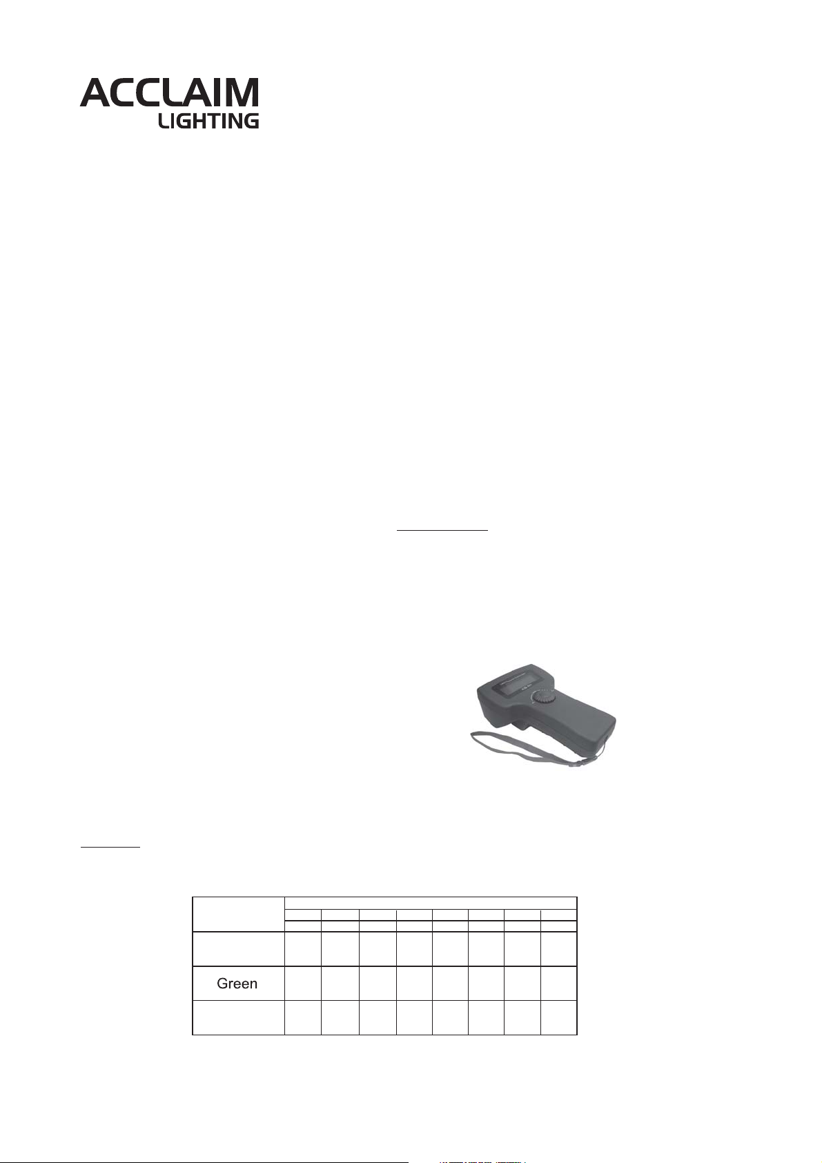
Programming:
A LED Setup Tool (depicted here) _XB-R1 is required to
program the X-CHIP DRV-TV. For further information,
please refer to its accompanying manual.
1. Slave Control(DMX Mode)
A LED Setup Tool(XB-R1)
(Sold separately)
In Slave Control, the settings for the addresses(001-512) and the Glide Effect functions can be adjusted
with a Setup Tool. There are 12 work modes for Slave Control.
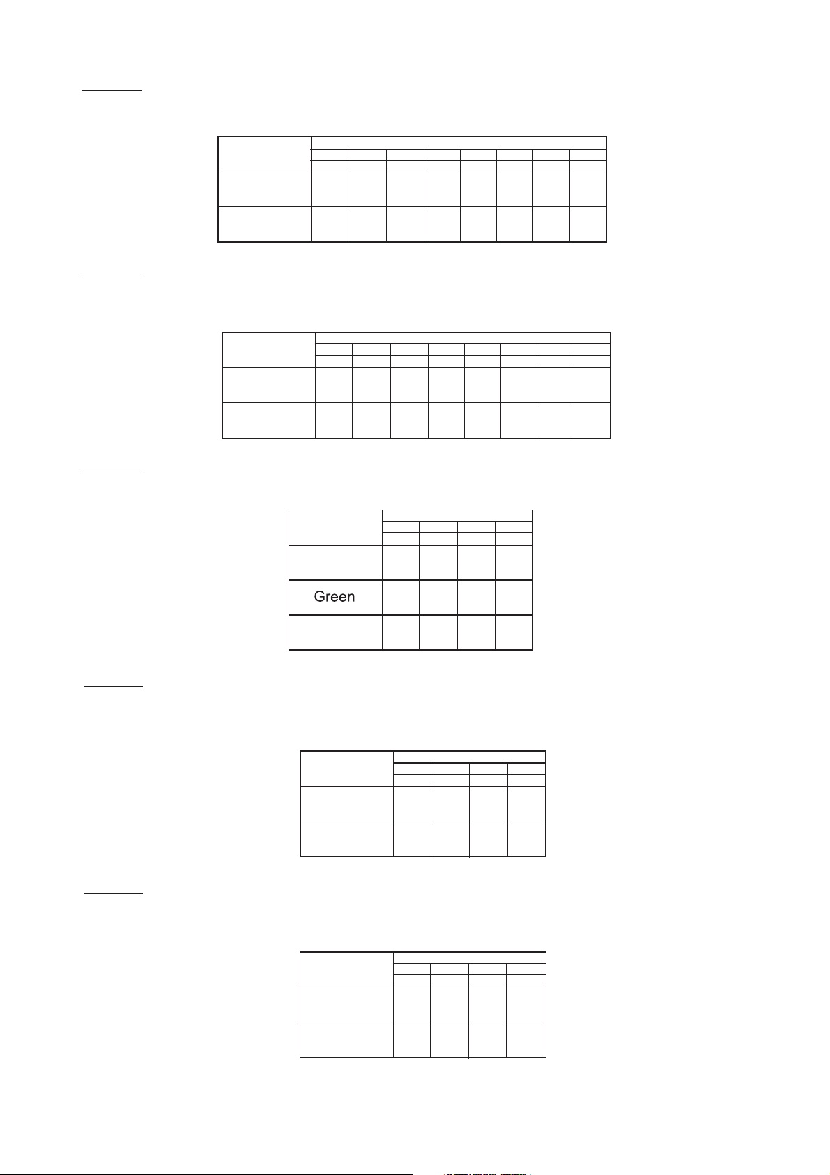
MODE-1
8 RGB mode: has 8 groups with RGB output, of which each group consists of 3 channels(24 channels in total).
Standard mode(24 channels in total=8x3 channels)
Color (R/G/B)
Red
Blue
Output 2 Output 3
Output 1
Group 1 Group 2
1
4 7 10 13 16 19 22
2
58
369
Channel 1-24 / Group 1-8
Group 3 Group 5 Group 6
Output 5 Output 6 Output 7 Output 8
Output 4
Group 4
17
14
11
12 15 18
Group 7
20 23
21 24
Group 8
24-004-2387-00
Rev 1.2
MODE-2
Color and intensity mode(16 channels in total=8x2 channels)
8 C&B mode: has 8 groups with color and intensity C&B output, of which each group consists of 2 channels
(16 channels in total).
C&B
Color
Output 2 Output 3
Output 1
Group 1 Group 2
1
35
Channel 1-16 / Group 1-8
Group 3 Group 5 Group 6
Output 5 Output 6 Output 7 Output 8
Output 4
Group 4
7
9
11 13 15
Group 7
Group 8
MODE-3
Brightness
2
46 10
8
Color mode(8 channels in total=8x2 channels)
12
14 16
(3) 8 COLOR mode: has 8 groups with Color control, of which each group consists of 1 channel
(8 channels in total). The brightness is always 100% in this mode.
Channel 1-8 / Group 1-8
Group 3 Group 5 Group 6
100%
Output 5 Output 6 Output 7 Output 8
Output 4
Group 4
5
67
4
100% 100% 100% 100% 100%
Group 7
Group 8
8
MODE-4
Output 2 Output 3
C&B
Color
Brightness
Output 1
Group 1 Group 2
123
100%
100%
Patch mode RGB of 24 outputs---->12 outputs(4x3 channels)
4 RGB mode: in this mode, 2 outputs are patched. The driver has 4 identical outputs distributed over 8 groups.
Channel 1-12 / Group 1-4
Output 3-4 Output 5-6
Color (R/G/B)
Red
Output 1-2
Group 1 Group 2
1
4710
2
58
Group 3
Output 7-8
Group 4
11
MODE-5
Blue
Patch mode C&B of 16 outputs---->8 outputs(4x2 channels)
369
12
4 C&B mode: has 4 groups with C&B output, of which each group consists of 2 outputs that are
controlled by 2 channels(8 channels ly).
Channel 1-8 / Group 1-4
Output 3-4 Output 5-6
MODE-6
C&B
Color
Brightness
Output 1-2
Group 1 Group 2
1
35
2
46
Patch mode Color of 8 outputs---->4 outputs(4x1 channels)
Group 3
Output 7-8
Group 4
7
8
4 COLOR mode: has 4 groups with Color control, of which each group consists of 2 outputs that are
controlled by 1 channel(4 channels in total). The brightness is always 100% in this mode.
Channel 1-4 / Group 1-4
C&B
Color
Output 1-2
Output 3-4
Group 1 Group 2
123
Output 5-6
Group 3
Output 7-8
Group 4
4
Brightness
100%
100%
100%
100%
-Page2-

MODE-7
Patch mode RGB of 24 outputs---->6 outputs(2x3 channels)
2 RGB mode: in this mode, 4 outputs are patched. The driver has 12 identical outputs distributed over 2 groups.
Channel 1-6
Output 5-8
Color (R/G/B)
Red
Output 1-4
Group 1 Group 2
1
4
2
5
MODE-8
Blue
Patch mode C&B of 16 outputs---->4 outputs(2x2 channels)
36
2 C&B mode: has 2 groups with C&B output, of which each group consists of 4 outputs that are controlled
by 2 channels (4 channels in total).
MODE-9
Patch mode Color of 8 outputs---> 2 outputs(2x1 channel)
C&B
Color
Brightness
Channel 1-4/Group1-2
Output 1-4
Group 1 Group 2
Output 5-8
1
2
3
4
2 COLOR mode: has 2 groups with Color control, of which each group consists of 2 outputs that are controlled
by 1 channel (2 channels in total). The brightness is always 100% in this mode.
Channel 1-2/Group1-2
MODE-10
C&B
Output 1-4
Group 1 Group 2
Color
Brightness
100%
Patch mode RGB of 24 outputs---->3 outputs(3x1 channels)
Output 5-8
12
100%
1 RGB mode: in this mode, 8 outputs are patched. The driver has 24 identical outputs distributed over 1 group.
Channel 1-3
Color (R/G/B)
Red
Group 1/
Output 1-8
1
2
MODE-11
Blue
Patch mode C&B of 16 outputs---->2 outputs(2x1 channels)
3
1 C&B mode: has 1 group with C&B output, which consists of 8 outputs that are controlled by 2 channels.
Channel 1-2
Group 1/
Output 1-8
1
2
MODE-12
C&B
Color
Brightness
Patch mode Color of 8 outputs---->1 outputs(1x1 channels)
1 COLOR mode: has 1 group with Color control, which consists of 1 output that is controlled by
1 channel. The brightness is always 100%.
C&B
Color
Channel 1
Group 1/
Output 1-8
1
Brightness
100%
-Page3-

NOTE:
1. The Glide Effect function can be switched on(YES) or off(NO). The transition from one level to another is
smoother when this function is switched on.
2. When this function is switched off, the lighting intensity will changed from one level to another abruptly.(thus,
when a quick lighting effect is required, the Guide Effect function should be switched off.)
3. If the DMX signal is interrupted, the driver will keep the last received DMX signal(information) until the driver
is switched off or a new and valid DMX signal is sent.
2.Master Control
AUTO mode and MANUAL mode are for Master Control. Relevant functions are as below:
(1) AUTO mode:
Preset programs:1-10 programs and "AUTO" program ( program is the sequential
running of these1-10 programs.)
Auto Speed: 1~100. Auto Fadetime: 0%~100%.
(2) MANUAL mode:
BLUE/Duration: 0%~100%.
NOTE:
1. The LEDs will turn red in Slave Control mode.
The LEDs will give responding sensitive when the parameters are adjusted in Master Control.
2. If the LED is not selected in "Setup with answer", it will turn red.
If the LED is not selected in :Setup no answer", it will switch off.
When the user confirms the settings of the LED products, the LEDs will flash momentarily to confirm that the
setting have been saved.
RED/Speed: .0%~100%
"AUTO"
GREEN/ Dimmer: .0%~100%
System connection diagram
DMX Controller
X-CHIP DRV-TV
(A Driver Unit)
DMX
through
Or
XB-R1
A Setup Tool
Power Supply
24VDC 24A max.
X-CHIP LED modules max 50pcs per channel,
Max 400pcs in total.
Notice:
Specifications and improvements in the design of this product and this manual are subject to change
without any prior notice.
-Page4-
 Loading...