

Access Music Virus C Owner's Manual

ACCESS VIRUS C SERIES
USER MANUAL OS5
ENGLISH VERSION


©2002 Access Music GmbH, Germany.
VIRUS is a trademark of Access Music GmbH.
All other trademarks contained herein are the
property of their respective owners. All features
and specifications subject to change without
notice.
Written by Christoph Kemper, Uwe G. Hönig,
Wiland Samolak and Marc Schlaile.
Translation by Thomas Green and Howard
Scarr. Graphic Design and DTP by
Babylonwaves Media.
http://www.access-music.de
info@access-music.de

2
1
Handling............................................................... 44
Content
IMPORTANT SAFETY REMARKS
All about the memory ...........................................47
The Modulation Matrix and Soft Knobs..................48
Random Patch Generator...................................... 50
Categories............................................................52
The Effects Section............................................... 52
Audio Inputs .........................................................53
Internal Audio Routing ..........................................54
Additional functions..............................................55
PROLOGUE
SYNTHESIS PARAMETERS
INTRODUCTION
The Virus ............................................................. 14
The Amplifier Envelope ........................................ 17
The First Filter...................................................... 18
Filter Modulation.................................................. 19
The Saturation Stage ........................................... 21
The Second Filter................................................. 21
Filter Routing ....................................................... 24
The First Oscillator............................................... 25
The Second Oscillator .......................................... 27
The Third Oscillator.............................................. 29
The Mixer Section ................................................ 29
The LFOs ............................................................. 30
The MOD Section ................................................. 33
Soft Knob 1/2....................................................... 33
Volume and Panorama Position............................ 34
Velocity................................................................ 34
Unison Mode........................................................ 35
The Effects........................................................... 36
The Arpeggiator ................................................... 38
SoundDiver Virus ................................................. 38
More to Come ...................................................... 39
OSCILLATORS ......................................................58
Oscillator-1/2/3 (Panel)......................................... 58
Oscillator (Edit-Menu)...........................................59
FILTER .................................................................63
Filters (Panel) .......................................................63
Filter Envelope...................................................... 64
Filter-Edit-Menu ...................................................65
ENVELOPES .........................................................69
MIXER .................................................................. 70
LFO AND MODMATRIX .........................................71
LFO (Panel)........................................................... 71
LFO (Edit Menu).................................................... 73
ARPEGGIATOR EDIT.............................................. 80
THE INTERNAL EFFECTS ...................................... 82
Distortion (Panel)..................................................82
Chorus (Panel)......................................................83
Chorus (Edit Menu)...............................................83
Phaser (Panel) ......................................................84
Phaser (Edit Menu) ...............................................84
Delay / Reverb......................................................85
Delay / Reverb (Panel) ..........................................86
Delay / Reverb (Menu) ..........................................87
Vocoder................................................................ 92
Analog Boost ........................................................ 92
Equalizer ..............................................................92
CONCEPT AND OPERATION
Operating Modes ................................................. 42
Master Clock and Midi-Clock ............................... 44

MAIN EDIT MENU
Common.............................................................. 96
Unison Mode........................................................ 99
Punch Intensity .................................................. 100
Envelope Sustain Time....................................... 100
Analog Inputs..................................................... 100
Follower (Envelope-Follower) ............................. 102
Ringmodulator ................................................... 102
Second Output/Surround.................................... 103
Velocity.............................................................. 104
Sound Category ................................................. 106
Soft Knob-1/2 .................................................... 106
MULTI MODE & SYSTEM SETUP
MULTI MODE PARAMETERS .............................. 110
SYSTEM ............................................................ 114
Keyboard ........................................................... 114
Input.................................................................. 116
MIDI................................................................... 117
System .............................................................. 121
THE KEYBOARD VERSIONS OF THE VIRUS
The VIRUS kc and the indigo ............................. 126
The Keyboard-Modes......................................... 128
THE VOCODER OF THE VIRUS
Vocoder ............................................................. 132
The parameters of the VIRUS Vocoder ................134
Notes about the vocoder: ................................... 137
ACCESS VIRUS OS5
Problems Related to Parameter Control ..............144
Arrangement Dump - The Sound in the Song......145
TIPS AND TRICKS
All abouts Inputs................................................. 148
About the Delay/Reverb ......................................149
The Virus as an Effect Device .............................150
Envelope Follower ..............................................150
Oscillators ..........................................................151
Filters................................................................. 153
Saturation for Added Grit and Dirt .......................153
LFOs ..................................................................154
Volume Control...................................................155
Assign and the Soft Knobs..................................156
Arpeggiator ........................................................156
How to modulate the Vocoder parameters ..........156
MIDI ...................................................................157
How to install Updates........................................158
APPENDIX
System Exclusive Data .......................................162
Parameter Descriptions ......................................166
Multi Dump Table...............................................178
Classes ..............................................................180
Mod Matrix Sources ..........................................182
Mod Matrix Destinations.....................................183
Soft Knob Destinations ......................................184
MIDI Implementation Chart .................................185
FCC Information (U.S.A) ......................................186
FCC Information (CANADA) .................................187
Other Standards (Rest of World).......................... 187
Declaration of Conformity ...................................188
Garantie Bestimmung.........................................189
Warranty ............................................................190
3
THE VIRUS AND SEQUENCERS

4
1
INDEX
INDEX ................................................................ 192

Important Safety Remarks

6
Important Safety Remarks
2
Please read all notes carefully before you power
the device up. A few fundamental rules on handling electrical devices follow.
SET-UP
• Operate and store the device in enclosed
rooms only.
• Never expose the device to a damp environment.
• Never operate or store the device in extremely dusty or dirty environments.
• Assure that air can circulate freely on all
sides of the device, especially when you
mount it to a rack.
• Don’t set the device in the immediate vicinity of heat sources such as radiators.
• Don’t expose the device to direct sunlight.
• Don’t expose the device to strong vibrations
and mechanical shocks.
CONNECTIONS
• Be sure to use exclusively the included
mains power supply adapter.
• Plug the device only into mains sockets that
are properly grounded in compliance with
statutory regulations.
• Never modify the included power cord. If its
plug does not fit the sockets you have available, take it to a qualified electrician.
• Always pull the power plug out of the mains
socket when you won’t be using the device
for prolonged periods.
• Never touch the mains plug with wet hands.
• Always pull the actual plug, never the cord,
when you’re unplugging the device.
OPERATION
• Don’t set beverages or any other receptacle
containing liquids on the device.
• Make sure the device is placed on a solid
base. Set it on a stable tabletop or mount it to
a rack.
• Make sure that no foreign objects fall into or
somehow end up inside the device’s housing. In the event that this should occur, switch
the device off and pull the power plug. Then
get in touch with an authorized dealer.
• Used on its own and in conjunction with
amps, loudspeakers or headphones, this device is able to generate levels that can lead to
irreversible hearing damage. For this reason,
always operate it at a reasonable volume level.
MEMORY BATTERY CHANGE
The VIRUS stores its sound programs in a battery-buffered RAM. This battery (general type
designation: CR2032) should be replaced every
three to four years. The housing has to be
opened to change the battery, so take the device to a qualified service technician. Do your
part in protecting our environment and take it to
a shop that disposes of batteries properly.
Before you have the battery changed, save the
entire memory content of the RAM by loading it
to a sequencer via "Total Dump". Be advised
that RAM content is lost when the battery is
swapped (see "Midi Dump TX" on page 117).).
CARE
• Do not open the device, it is not equipped
with any user-serviceable parts. Repair and
maintenance may only be carried out by qualified specialists.

• Use only a dry, soft cloth or brush to clean
the device.
• Do not use alcohol, solvents or similar
chemicals. These can damage the surface of
the housing.
FITNESS FOR PURPOSE
This device is designed exclusively to generate
low-frequency audio signals for sound engineering-related purposes. Any other use is not
permitted and automatically invalidates the
warranty extended by Access Music Electronics
GmbH.
ACCESS VIRUS OS5
7

8
Important Safety Remarks
2

Prologue

10
CHAPTER 3
Prologue
Dear VIRUS Owner,
Congratulations on your choice, the new VIRUS. You have purchased a cutting-edge synthesizer that comes fully loaded with several
revolutionary features. Here are just a few of the
highlights:
The VIRUS delivers the sound characteristics
and tone of traditional analog synthesizers in a
previously unparalleled level of quality and handling ease. We’re not kidding, the VIRUS actual
delivers the authentic response of an analog
synth via a digital signal processor chip, although the sound shaping and voicing options
out-perform those of it historical predecessors
by a considerable margin.
The VIRUS comes with up to 1024 slots for
storing SINGLE sounds. These are organized in
eight banks. The first two banks (A and B) are
located in the RAM, so you can overwrite them
with new sounds. The other six banks are
”hard-wired”, i.e. they’re programmed into the
FLASH ROM. To make use of the banks E-H
you need to install the second1024.mid file first
(“The 1024 sounds update” on page 158).
The VIRUS offers a maximum of 32 voices. In
Multi Mode, these are allocated dynamically to
sixteen simultaneously available sounds.
You have no less than three audio oscillators
plus one suboscillator, a noise generator, a ring
modulator, two Multi Mode filters, two envelopes, a stereo VCA, three LFOs and a saturation stage (SATURATOR) for cascade filtering,
tube and distortion effects.
delay unit that lets you create high-quality reverb effects and rhythmic delay taps. Delay
time can be synced up to MIDI clock.
With the benefit of two external audio inputs,
the VIRUS may also serve as an FX device and
signal processor that you can use creatively to
come up with all kinds of effects. External signals can be processed with filter, gate and lo-fi
effects, routed to the VIRUS effects section and
serve as a modulation source for frequency and
ring modulation.
Beyond that, you can use internal or external
signals as sources for the VIRUS’ on-board
vocoder serve. The vocoder works with up to
32 filter bands and offers diverse manipulation
and modulation options.
The three main oscillators produce 66 waveshapes, three of which are dynamically mixable
so that spectral effects are possible within the
confines of a single oscillator. In conventional
synthesizers, this type of effect requires several
oscillators. Synchronization, frequency modulation and ring modulation between the audio oscillators delivers additional complex spectral
effects that you can use for all kinds of sound
shaping purposes.
The filters can be switched in series or in parallel within the voices via several options. When
you switch the filters in series, the saturation
stage is embedded between the filters. Consequently, an overdriven filter resonance can be
re-filtered within the same voice! A maximum of
six filter poles (36 dB slope!) enables radical
tonal manipulations.
The VIRUS offers a veritable arsenal of effects.
You have seven powerful sound-sculpting functions, including chorus, phaser and distortion,
at your disposal, with each effect available separately for every sound. Thus, in 16-way MULTI
mode, the VIRUS offers over 98 effects, no
less!. Among them you also get a global reverb/
The LFOs feature 68 continuous variable waveshapes each, including a triangle with variable
symmetry and infinitely variable aperiodic oscillations for random variation of the controlled
parameters. The LFOs are capable of polyphonic as well as monophonic oscillation. In
other words, if several voices are active, the

LFOs can run independently or in sync. A
number of keyboard trigger options enable you
start LFO waveshapes with variable phase
lengths at the beginning of a note and/or to cycle once only, like an envelope.
Next to the numerous ”hard-wired” or fixed
modulation configurations, you can assign
three modulation sources to up to nine different
modulation destinations via the Modulation Matrix. For your modulation sources, you have
LFOs, velocity, the pitch bender, aftertouch, the
modulation wheel, numerous MIDI controllers
and other sources to chose from. For your
modulation destinations, you can select any
sound parameter of the VIRUS that is conducive to being remote controlled.
Up to 16 arpeggiators are available in MULTI
mode. These give you countless options for
creating arpeggios, which can also be synced
up to MIDI clock.
Sounds and effects are patched out via six audio outputs which of course can also be used to
route three stereo signals out.
In additional to its killer sounds and tone, the
VIRUS was designed to deliver ultimate handling and control comfort. It is equipped with
dedicated knobs and buttons for the crucial
synthesizer functions, further parameters are
accessible via data entry procedures. We distinguished between these two levels of expertise
to enable you to create complex sounds while
keeping the user interface as clear and uncluttered as possible.
In all modesty, we are especially proud of a feature we developed called Adaptive Parameter
Smoothing. For the first time in the history of
synthesizers equipped with memories, you can
manipulate a knob or control feature without an
audible step or increment. In other words, the
sound does not change abruptly but SEAMLESSLY. No more zipper noises! The VIRUS re-
ACCESS VIRUS OS5
sponds just as smoothly as analog synthesizers
did prior to the introduction of digital sound
storage
And users of contemporary software sequencers will appreciate the fact that the VIRUS
sends all sound shaping commands immediately in the form of MIDI Controller or Poly Pressure data (and of course accepts all of the
corresponding Controller and SysEx messages). This feature lets you dynamically control the
VIRUS and all its functions via computer.
Although far from complete, the features listed
above give you some indication that you now
own an exceptionally versatile, high-quality musical instrument that will give you plenty of joy
for years to come. We certainly hope you can
fully exploit the enormous potential of this fine
instrument.
Have fun and enjoy!
Your VIRUS Development Team
By the way: a rack mounting kit is optionally
available for the Virus C. Feel free to get in
touch with your local authorized dealer for more
info.
Many thanks to:
Ben Crosland, Maik Fliege, Thomas Green, Axel
Hartmann, Uwe G. Hönig, Jörg Hüttner, Timo
Kaluza, Oliver Käser, Andrea Mason, Thorsten
Matuschowski, Jörg Meißner, Paul Nagel, Kai
Niggemann, Rob Papen, Matt Picone, Wieland
Samolak, Daniela Sauerbier, Howard Scarr,
Hans-Jörg Scheffler, Shehryar Lasi, Jenny Simon, Matt Skags, Joeri Vankeirsbilck, Jay
Vaughan, Jens Wegerhoff and Daniel Wewer.
11

12
CHAPTER 3
Prologue

Introduction

14
CHAPTER 4
Introduction
THE VIRUS
This section provides deliberate, step-by-step
guidelines on operating and handling the VIRUS
for those of you who are new to the world of
synthesizers and MIDI. The following covers basics such as how to connect the VIRUS to an
AC power supply, your MIDI system and your
audio system. Then we will guide you through a
series of experiments designed to demonstrate
the different functional groups, their control features and the tasks they execute.
After you have finished reading this section, you
will be able to handle virtually all of the sound
generating and sound shaping functions of the
VIRUS. All of these are described in context,
along with their control features. Even the majority of less significant functions, accessible via
menus, are discussed here. You will find a detailed, comprehensive description of all functions of your new synthesizer in the section
following this introduction.
Please keep in mind that within confines of this
introduction, we are unable to impart all of the
knowledge and skills in acoustics, sound synthesis and MIDI control you might desire or
need to acquire. If you are keen to learn more
about these subjects, you should consider becoming a regular reader of one or several of the
leading trade publications in your country. Your
local musical instruments dealer or more experienced musicians will be able to recommend
the best magazines to you. And of course there
is a wide range of books available on these
subjects.
If you decide to read this section, we recommend you read it in its entirety from the start rather than begin with a subsection that is of
particular interest to you. A fitting metaphor for
the basics discussed in this section might be a
house where each bit of information in a sub-
section is a brick that builds on a preceding
brick and interlocks with those next to it. You
want your knowledge base to be a sound structure so you won’t run into problems when you
find one of the “bricks” is missing.
CABLE CONNECTIONS
Before you connect the VIRUS to an AC outlet
and the rest of your equipment, ensure that all
of the devices are switched OFF. If your VIRUS
does not have a build-in keyboard, then connect the MIDI OUT of the desired MIDI send device (keyboard, computer, hardware sequencer,
etc.) with the MIDI IN of the VIRUS.
Connect the audio outputs of the VIRUS with
the signal inputs of your audio system. In order
to receive a signal, as a minimum you must
connect the output OUT 1 R/MONO. However,
we recommend you also connect the output
OUT 1 L so you are able to enjoy the stereo
sounds of the VIRUS.
Once you have established the desired cable
connections, make sure the main volume controls of all the connected devices (VIRUS: MASTER VOLUME, located at the upper left hand of
the control panel) are dialed to the lowest possible setting. Switch the devices on in the following sequence: the MIDI send device
(computer, master keyboard, etc.) first, then the
sound generators (VIRUS and the other signal
sources), followed by the mixing console and finally the amplifier.
Now while you are sending notes on MIDI
Channel 1 of the VIRUS, turn the master volumes of the connected devices up in the same
order that you switched the devices on. Be sure
to keep on eye on the signal level indicators of
your mixing console.

SOFT KNOB 1
SINGLE
MULTI
UNDO
STORE
MULTISINGLE
MASTER VOLUME
Controls the overall volume of the VIRUS. This
control determines the volume of the signal pair
piped through Output 1 before it is converted
into an analog signal. This means that under
normal circumstances, you should turn Master
Volume all they way up because you of course
want the VIRUS to deliver the most dynamic
signal possible.
LISTENING TO THE FACTORY SOUNDS
The program memory of the VIRUS was loaded
with sound programs (SINGLE PROGRAMs)
and sound combinations (MULTI PROGRAMs)
before it left the factory. To hear the SINGLE
PROGRAMs (and gain an initial impression of
the possibilities your new instrument has to offer in terms of sounds), first make sure your
MIDI source is sending on MIDI Channel 1.
ACCESS VIRUS OS5
The Virus
and so on, simply use the PARAMETER/BANK
buttons to step from one program bank to another.
You’ll find that some sound programs are labeled with the abbreviations ”INP” or ”VOC”.
These use the external audio input as a signal
source for the filter section (INP) or vocoder
(VOC). This means that you won’t hear anything
until you route an audio signal into the external
audio inputs.
UNDO
STORE
MULTISINGLE
SINGLE
MULTI
-
SOFT KNOB 1
+
15
Press the SINGLE button. A number, a letter,
number and name appear in the display. These
indicate the the MIDI Channel, the current Program Bank (A to D or A to H) as well as the
number and name of the current sound program.
Now if you play notes you should be able to
≤
hear this sound and a
note (the round dot at
the end of the note staff is solid black) should
appear in the display every time you press a key
and release a key. If you do not hear a sound
but you see a half note (blank note head) check
to see if you are sending on the wrong MIDI
Channel.
Press the VALUE button to call up the 128 single programs of Bank A in sequence. (The VALUE pot is inactive in this operating mode.) In
order to hear the sound programs in banks B, C
Tip: You can trigger a note on the Virus by
pressing both the EDIT and SYNC buttons in
the OSCILLATORS section at the same time –
this is the AUDITION function, which is especially useful for auditioning sounds when there
is no keyboard connected to the Virus.
Call up each of the 128 programs in Bank A in
turn. You can do this either with the VALUE
keys (which simply increment/decrement the
program number), or by holding down the MULTI key and scrolling through programs with the
VALUE knob. To try out all the other sounds in
banks B to H, simply switch banks with the PARAMETER/BANK buttons.

16
CHAPTER 4
Introduction
SOUND CATEGORIES
To help you find the type of SINGLE sound you
are looking for more quickly, the Virus operating
system lets you define so-called „categories“
and save this information together with each of
your SINGLE sounds.
Available categories are:
Off, Lead, Bass, Pad, Decay, Pluck, Acid, Classic, Arpeggiator, Effects, Drums, Percussion, Input, Vocoder, Favourite1, Favourite2,
Favourite3
Each SINGLE sound can „belong“ to two categories at the same time. Of course the categories of all the presets in Banks C to H are fixed,
but for sounds in the RAM Banks (A and B) they
can be defined and saved together with the
program.
To search for sounds in a specific category (in
SINGLE or MULTI-SINGLE mode):
Press and hold the SINGLE button. This causes
the currently selected category to appear in the
display, and it can be changed by stepping up
or down with the Parameter buttons. Having
found the category you want, do not release the
SINGLE button and scroll through the sounds
using the Value buttons. Release the SINGLE
button when you have found what you are looking for. SINGLE sounds which do not belong
to the currently selected category are simply
skipped over.
lect these combination programs via the VALUE
button. The VIRUS features “only” 128 MULTI
PROGRAMs, so you don’t have to switch back
and forth between banks they way you just did
while activating single programs.
The majority of available MULTI PROGRAMs
contain sound combinations that are controlled
via a single MIDI channel. In these MULTI PROGRAMs, the sounds involved are allocated
side-by-side (split) or on top of one another
(layered) on the keyboard. In other MULTI PROGRAMs, the sounds are divided up over several
MIDI channels to make it easier to work with a
sequencer. If you activate a MULTI PROGRAM
and hear a single sound only, then you can control this MULTI PROGRAM via several channels.
YOUR FIRST SOUND PROGRAM
If you have never created or changed a sound
on a synthesizer, we now have the pleasure of
introducing you to this fascinating process.
Select the single program “C127 - START -”.
Press any key on the connected keyboard. You
should hear a sound that, for lack of better description, is a bit harsh or biting, but above all
completely static. It should start immediately
after you press a key and sustain indefinitely for
as long as you hold the key down. As soon as
you release the key, the sound should end
abruptly. This sound is not designed to be especially pleasant; it is intended to be as neutral
as possible to give you a basis from which you
can begin creating or shaping your own sound.
LISTENING TO THE MULTI PROGRAMS
The VIRUS not only has the capability of playing
SINGLE PROGAMs, but also combinations
consisting of more than one sound simultaneously (MIDI Multi Mode). To call up the MULTI
PROGRAMs, press the MULTI button and se-
ATTACK
DECAY
SUSTAIN
RELEASE
12
12
12
12
AMPLIFIER
THE AMPLIFIER ENVELOPE
Long-term exposure to this sound will definitely
grate on your nerves, so let’s get started with
changing it into a signal you might enjoy hearing, beginning with the volume characteristics.
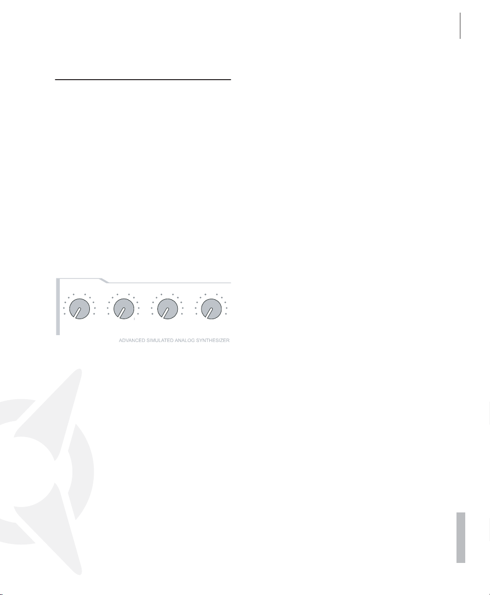
Locate the section labeled AMPLIFIER at the
bottom right of the control feature panel of the
VIRUS. Here you can see four pots labeled ATTACK, DECAY, SUSTAIN and RELEASE, respectively.
These controls will help you to dial in volume
characteristics called an amplifier envelope and
put an end to the nerve-racking drone that may
remind you of one of those cheesy organs that
you hear in ‘60s B-movie sound tracks.
Rotate the ATTACK pot while you repeatedly
AMPLIFIER
6
0
ATTACK
12
0
6
DECAY
6
12
0
SUSTAIN
12
engage a key to hear the note. The further you
turn the pot up, the longer it takes for the sound
to achieve maximum volume after the start of
the note. So you can say ATTACK controls the
initial volume swell of the sound.
Presumably the ATTACK pot was set to a random position before you made any adjustments. Nevertheless the volume automatically
increased to the maximum level before you
started rotating the pot. The reason for this is
that an ATTACK value of 0 is saved in the sound
program - START - and this value remains valid
until you determine a new value by adjusting
the position of the pot, even if you turn it ever
so slightly.
0
RELEASE
6
12
ACCESS VIRUS OS5
The Amplifier Envelope
Take a look at the display of the VIRUS to gain
an impression of the difference between these
two values. It shows two numeric values when
you dial a pot: at the left you can see the value
stored in the sound program and at the right,
the numeric equivalent to the value determined
by the current position of the pot.
Always keep in mind that for a programmable synthesizer the position of the control feature or pot does not necessarily indicate the
actual value of the given function. The reason
for this is that when you first activate a sound
program, it will reflect the programmed value.
You have to adjust the control feature before
the programmed value is superseded by the value you determine manually.
Now fiddle with the DECAY pot while you repeatedly press a key to activate a note. Hold
the key down for good while. You will notice
that the volume, once it reaches maximum level
at the end of the ATTACK phase, drops until it
reaches a minimum level. The DECAY pot determines the speed, or in synthesizer jargon, the
rate at which the volume decreases.
However, the DECAY level does not always
drop to the minimum level; you can determine a
random value between the maximum and minimum levels at which the volume remains constant. This level in turn is controlled via the
SUSTAIN pot.
Whenever the SUSTAIN level is set to maximum, the volume cannot drop during the DECAY phase; in other words, in this situation the
DECAY pot is ineffective.
The individual functions of a synthesizer are
designed to interact; many functions are dependent on other functions. In a number of cases
this means that some functions are subordinate
17
18
-100%
100%
1+2
FILTER BALANCE
CUTOFF
RESONANCE
ENV AMOUNT
CUTOFF 2
SELECT
MODE
FILT 1
FILT 2
EDIT
BP
BS
HP
LP
FILT 2
FILT 1
12
12
FILTERS
CHAPTER 4
Introduction
to others, i.e. the effectiveness of a control feature is altered, modified or even negated completely by other related functions.
The final pot, RELEASE, determines the speed
or rate at which the volume decreases when
you release the key: At low values the sound
ends relatively abruptly, at high values, the
sound fades out more gradually and softly. The
length of the RELEASE phase also depends on
which level the amplifier curve is at when you
release the key: The lower the level, the shorter
the RELEASE phase. If you dialed in a brief DECAY or SUSTAIN-TIME phase and it ended
while you held the key down then of course
there will not be an audible RELEASE phase.
The amplifier envelope can be described as a
variable curve which, depending on the type
and duration of attack, hold and release data,
automatically influences an imaginary volume
pot (turns it up or down). At the beginning of the
note, ATTACK controls the rise or rate of increase to the maximum level. Once the maximum level is achieved, DECAY determines the
fall or rate of decrease to the SUSTAIN value,
which is infinitely variable between the minimum and maximum levels. The amplifier envelope may remain at this value until the end of
the note, fall towards the minimum level as determined by the variable TIME value, or even
rise again towards the maximum level. After the
end of the note, RELEASE controls the fall or
rate of decrease to the minimum level. Consequently, the control pots labeled ATTACK, DECAY, TIME and RELEASE control a speed or
rate, where as SUSTAIN actually controls a level.
THE FIRST FILTER
Now we will take a look at a component of a
synthesizer that is generally regarded as the
most important functional unit as it enables
drastic sound shaping measures: the filter - or
in the case of the VIRUS, the two filters.
But first we will concentrate on just one of the
two filters.
FILTERS
6
12
0
CUTOFF
0
-
6
6
CUTOFF 2
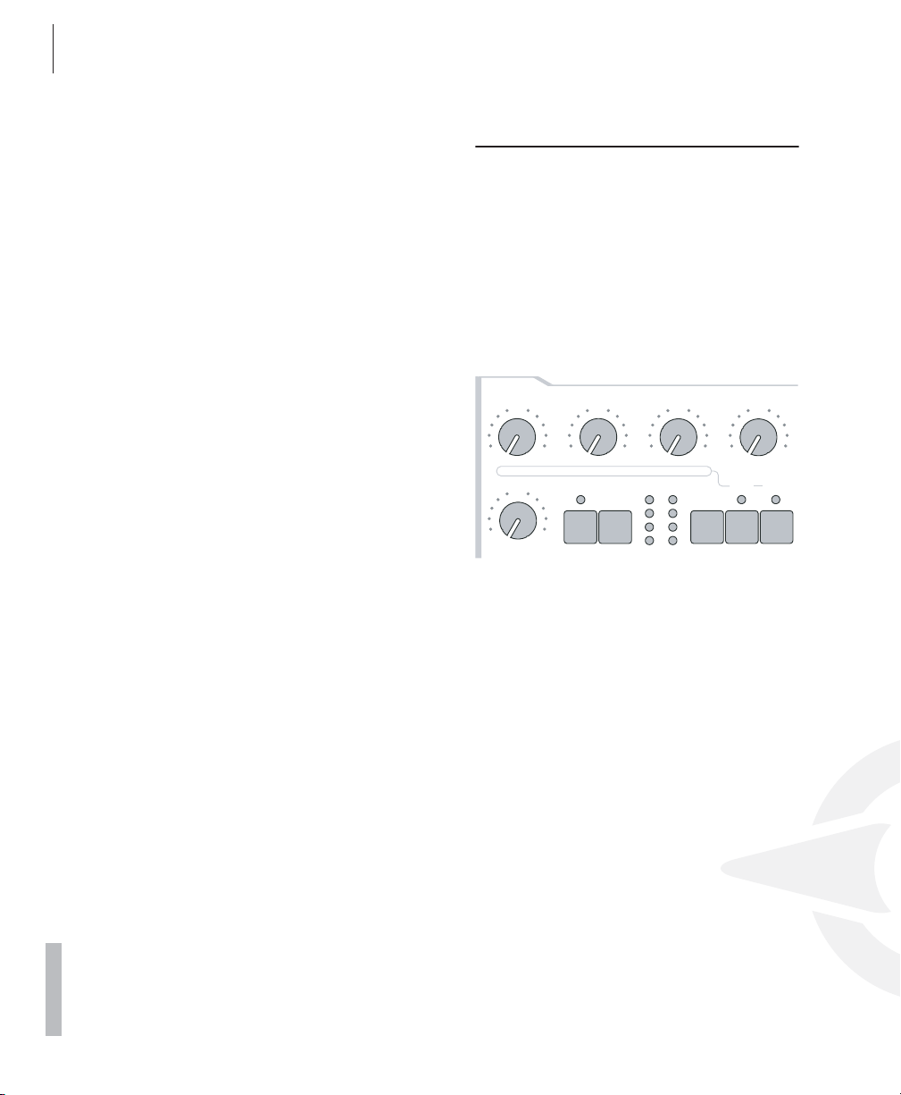
Locate the Cutoff pot (not to be confused with
Cutoff 2!) in the section labeled FILTERS, directly above the section labeled AMPLIFIER. Rotate
the pot to the left and right and note how the
sound becomes muddier and clearer in response to the direction in which you turn the
pot. (To ensure this effect and the following aural experiments are most pronounced, adjust
the amplifier envelope so that the VIRUS generates a constant level while you hold a key
down).
This is how a low pass filter works: it suppresses, or in technical jargon, attenuates the higher
frequencies in a signal and allows the lower frequencies through. Think of the Cutoff pot as a
bouncer and the VIRUS as your pub. You can
tell it which frequencies to let in and which frequencies to keep out. The frequencies above
the so-called cutoff or filter frequency are suppressed, those below it remain unaffected.
6
0
RESONANCE
EDIT
FILT 1
12
-100%
ENV AMOUNT
LP
HP
BP
BS
MODE
0
100%
FILT 2
1+2
1
FILTER BALANCE
FILT 2
FILT 1
SELECT
2

SELECT
MODE
FILT 1
FILT 2
EDIT
BP
BS
HP
LP
FILT 2
FILT 1
Now locate the FILT 1 MODE switch, which is
also located in the FILTERS section. It enables
you to select a filter operating mode from the
four available options:
- LP the low pass filter we have just discussed.
- HP the high pass filter which works in the op-
posite manner of the low pass filter: It suppresses the lower frequencies in a signal and
lets the higher frequencies pass.
- BP the band pass filter which suppresses
both ends of the tonal spectrum and allows
only a narrowly defined bandwidth of the
original sound to pass.
- BS The band stop filter, band reject filter or
notch filter which works in the opposite manner of the bandpass filter. It allows all of the
frequencies of a signal except for a narrow
frequency band around the cutoff to pass.
The term “notch” is fairly descriptive; you
might say this filter chops a notch out of the
sound spectrum.
LP
HP
BP
BS
EDIT
FILT 1
MODE
FILT 2
Now activate the different operating modes and
rotate the Cutoff pot to get a feel for the way
each filtering option works.
Along with the Cutoff pot, the RESONANCE pot
is the most important control feature of a filter.
The filter resonance increases the volume of the
frequencies located near the cutoff frequencies
and suppresses the more remote frequencies.
This sound shaping feature has a striking effect
- especially when used in conjunction with the
low pass filter: it produces a nasal or honking
type of tone which increases as you turn the
FILT 1
SELECT
FILT 2
ACCESS VIRUS OS5
Filter Modulation
resonance up. Experiment by varying the RESONANCE setting in the different operating
modes in conjunction with different Cutoff settings. You will find the effect that the RESONANCE pot achieves is markedly different for
the band stop filter in comparison to the effect it
has on the other filter types: as the resonance
increases, the bandwidth of the notch decreases; in other words more frequencies on both
sides of the filter frequency are allowed to pass.
FILTER MODULATION
Of course we don’t want to require you to execute every sound modification manually by
twiddling pots. All kinds of sound modifications
in the VIRUS can be executed automatically
much in the way of your previous experiments
with the volume controls: The amplifier envelope can be described as a variable curve
which, depending on the type and duration of
attack, hold and release data, automatically influences (turns it up or down) an imaginary volume pot.
Similar procedures are applicable to the filter
frequencies. The FILTERS section features its
own envelope, the structure of which is identical to the amplifier envelope, located directly
above the amplifier envelope on the control feature panel. Much like the amplifier envelope, the
filter envelope automatically “rotates” the Cutoff
pot.
However there is one significant difference between the two envelopes. With the amplifier envelope, you are always dealing with an initial
volume level of 0 because of course you want
absolute silence prior to the beginning of a
note. After the RELEASE phase, it is again
19

20
-100%
100%
CUTOFF
RESONANCE
ENV AMOUNT
12
12
CHAPTER 4
Introduction
highly desirable that your box is silent. With the
filter envelope, the situation is somewhat different: It always starts at the Cutoff value that you
determined manually. And it is definitely not always desirable that the filter frequency is
brought to the maximum level.
0
CUTOFF
6
12
6
0
RESONANCE
12
0
-100%
ENV AMOUNT
100%
Consequently, you need a tool that limits the effective range of the filter. This is why we
equipped the VIRUS with a control labeled ENV
AMOUNT (short for Envelope Amount). When
the pot is turned counter-clockwise to the far
left, the filter has no effect on the cutoff frequency; the further you turn the pot to the right,
the greater the effect the filter envelope has on
the filter frequency. The maximum level of the
envelope may lie outside the audible range
when the filter has already been partially
opened via the Cutoff pot or was manipulated
via other control options. In extreme cases
where the filter is already completely open, the
filter frequency cannot be increased regardless
of how high you set the ENV AMOUNT.
Go ahead and spend some experimenting with
different ENV AMOUNT, Cutoff and RESONANCE settings for the diverse filter operating
modes. Also try varying the settings for the amplifier envelope. You will find that with just these
few parameters you are able to come up with a
vast amount of sound settings. If you are
among the many musicians who are associative
listeners, you might say many of the settings
produce sounds reminiscent of stringed-instruments; some sound picked, plucked or
snapped, others sound bowed.
For your next experiment set the amplifier envelope so that you hear a constant level when you
press and hold a note. Now deactivate the filter
envelope by setting the ENV AMOUNT to 0. Set
Filter-1Filter-1 to low pass mode and decrease
the filter frequency until you just barely hear a
muddy signal when you play notes in the midrange.
Now play a few higher and lower notes. You will
find that the lower notes have a greater overtone content, whereas the higher notes sound
muddier and their volume decreases until the
notes are completely inaudible. You might already suspect what this is all about: As the
notes are transposed ever lower, more portions
of the signal fall below the cutoff frequency,
whereas with the notes that are transposed ever higher, more portions of the signal rise above
the cutoff frequency and subsequently are suppressed until the root note and the last audible
portion of the signal is silenced.
To avoid this effect - or if desirable, to amplify it
- you have the option of influencing the cutoff
frequency via the pitch of the note, i.e. the note
number. The degree of influence is determined
by the KEY FOLLOW. You find this parameter
within the Filter Edit menu.
Please note that KEY FOLLOW is a so-called
bipolar parameter: Its control range is not limited to the positive end of the spectrum (0 to a
maximum of 127). Bipolar controls effect negative values as well, in this case from the negative maximum of -64 through 0 an on to the
positive maximum of +63. Consequently, if this
pot is set to the center position (12 o’clock or 0)
the pitch of the notes corresponding to the keys
on your keyboard has no effect on the cutoff
frequency. If on the other hand you turn the KEY
FOLLOW pot clockwise towards the positive
control range, you will find that the filter opens
up increasingly as the pitch increases with higher notes. At lower notes, the filter closes down
again. If you turn the pot counter-clockwise to-

OSC VOL
wards the negative control range, the KEY
FOLLOW effect is reversed. With the VIRUS,
you will encounter this feature - intensity control
via a bipolar parameter - again in conjunction
with other modulation sources and targets.
Now experiment as much as you like with different KEY FOLLOW settings and tune the settings via the Cutoff pot. And remember to bring
all of the other parameters you have encountered thus far into play.
THE SATURATION STAGE
In the signal chain of the VIRUS, Filter-1 is followed by a saturation stage. It enables you to
add overtones to the filtered signal via distortion. Locate and press the button labeled EDIT
in the FILTERS section.
ACCESS VIRUS OS5
The Saturation Stage
position (12 o’clock) determines the volume of
the filter section’s input signal. The portion of
the control range located to the right of the
center position (12 o’clock) does not achieve
any increase in volume; it simply intensifies the
degree of saturation or distortion. This effect is
only achieved when you have activated a saturation curve. The intensity of the remaining
available DSP effects is also controlled via the
OSC VOL knob.
0
-
6
Feel free to experiment with the diverse saturation curves and be sure to vary the OSC VOL
settings. Note how the different Cutoff and
RESONANCE settings influence the saturation
curve.
6
OSC VOL
21
01111111111111111112
1 SATURATION
Curve Off≤
61111111111111111154
The display will read ”SATURATION CURVE
OFF”, which means exactly what it says. With
the VALUE buttons or the VALUE pot, you can
now select from a number of saturation/distortion curves. Next to the distortion curves, the
SATURATION stage offers further DSP effects
such as the shaper, rectifier and filter. These are
explained in detail in the section on the SATURATION stage.
At this point we would like to mention the OSC
VOL pot in the MIXER section. The portion of
the control range from the far left to the center
THE SECOND FILTER
You probably noticed that by a adding a bit of
saturation to the signal you can come up with a
pretty heavy, aggressive sound - especially with
a low filter frequency level and high resonance.
Yo u’re probably thinking these types of sounds
could do with some more filtering. We had the
same idea, which is one of the reasons why we
equipped the VIRUS with another filter per
voice.

22
FILTER BALANCE
CUTOFF
RESONANCE
ENV AMOUNT
CUTOFF 2
SELECT
MODE
FILT 1
FILT 2
EDIT
BP
BS
HP
LP
FILT 2
FILT 1
CHAPTER 4
Introduction
The technical design of this second filter is
identical to the first, so we won’t discuss it in
as much detail as we did the first filter. However, there are few differences in how you handle
the second filter:
• Only two control features of the VIRUS are allocated exclusively to Filter-2: Cutoff-2 and FILT
2 MODE.
• The RESONANCE, ENV AMOUNT and KEY
FOLLOW pots can be allocated to either of the
two filters or both simultaneously. Use the two
SELECT-buttons located at the far right of the
FILTERS section to select the desired operating
mode. For instance, if you press the FILT 2 SELECT button, then the values you set via the
RESONANCE, ENV AMOUNT and KEY FOLLOW pots apply exclusively to Filter-2. The
corresponding parameters of Filter-1 remain unaffected. On the other hand, if you press both
SELECT buttons at the same time, the values
that you dial in apply by the same measure to
Filters 1 and 2.
In the sound program we are using for our experiments, the LEDs of both buttons are illuminated, so that all adjustments to the given
parameters affect both filters. However, you
have yet to actually hear the effect of Filter-2 on
the signal because it is mixed out of the audible
signal path of the VIRUS.
CUTOFF
-
6
CUTOFF 2
0
RESONANCE
6
EDIT
FILT 1
ENV AMOUNT
LP
HP
BP
BS
MODE
FILT 2
FILTER BALANCE
FILT 1
SELECT
Before we get started with our next experiment,
deactivate SATURATION, set the ENV AMOUNT
of the filter envelope to zero and set Cutoff 2 to
the center position (12 o’clock) so that Filter-2
always has the same cutoff frequency as Filter-
FILT 2
1 (we’ll explain Cutoff 2 a bit later). Set Cutoff to
a medium or middle value and turn the RESONANCE pot counter-clockwise to the far left to
achieve a relatively muddy sound. Now locate
the FILTER BALANCE pot at the upper right
hand of the control panel and rotate it from the
left to the right. You will note the sound becomes muddier as you turn the pot towards the
center position (12 o’clock) and that the sound
is somewhat brighter at the far right of the control range then at the far left.
The reason for this effect is that when you turn
the FILTER BALANCE pot to the far left, only Filter-1 is audible. When you rotate the pot to the
right, Filter-2 is blended in so that it follows Filter-1 in the signal chain. When you turn the FILTER BALANCE pot clockwise, Filter-1 is
blended out of the signal chain until at the far
right position only Filter-2 is active and audible.
Each filter in the VIRUS normally features 2
poles. However in the FILTER ROUTING operating mode SER 6, Filter-1 operates with 4
poles, so the signal patched through Filter-1
(FILTER BALANCE to the far left) is trimmed
more drastically than when it is routed through
Filter-2 (FILTER BALANCE to the far right).
When you set the FILTER BALANCE pot to the
center position (12 o’clock) - as we mentioned
before - the two filters are routed in series,
which means they respond as if they were a single filter with 6 poles and consequently a great
deal of slope. This is why the input signal is
trimmed substantially when you set the pot to
this position.
Experiment with the diverse FILTER BALANCE
positions to get a feel for the different degrees
of slope. Rotate the Cutoff pot or activate the
filter envelope (for both filters!) to hear the filters
in action.
The Cutoff 2 pot is a special feature: It controls
the cutoff frequency of the second filter, but is
subordinate to the Cutoff pot located above it.

In other words, at the center position (12
o’clock) the manually selected frequency of Filter-2 is identical to that of Filter-1. When you rotate the pot to the left the cutoff frequency level
of Filter-2 is increased relatively to Filter-1,
when you turn to pot to the right the cutoff frequency level is decreased relatively. Now when
you adjust the Cutoff pot, you adjust the cutoff
frequency of both filters by the same measure!
This feature lets you determine a difference in
values in the filter frequencies (called an offset)
via the Cutoff2 pot which remains constant
whenever you adjust the Cutoff pot.
Yet another experiment in which you can come
up new filtering characteristics that are typical
of the VIRUS:
Set the FILTER BALANCE pot to the center position (12 o’clock) and Cutoff 2 to the maximum
level. The FILTER ROUTING operating mode
must remain SER 6. Set Cutoff and RESONANCE to a middle value and select a clearly
audible SATURATION curve.
ACCESS VIRUS OS5
The Second Filter
Now experiment with the diverse filter modes
and listen closely to the effect of the parameters RESONANCE, ENV AMOUNT and KEY
FOLLOW in conjunction with the SELECT button. Please also keep in mind that the chances
of choking a sound off are substantially greater
when you are using both filters: For instance, if
the first filter is used as a low pass with a low
cutoff frequency and the second as a high pass
with a high cutoff frequency, the VIRUS will not
generate an audible signal when you set the
FILTER BALANCE pot to the center position (12
o’clock).
23
Now you can filter this complex signal produced by a combination of the saturation stage
and the Filter-1 yet again. Rotate the Cutoff 2
pot slowly towards the center position (12
o’clock). You can hear how Filter-2 gradually
modifies the distorted signal. You can set a
RESONANCE value for Filter-2 if you press the
FILT 2 SELECT button and rotate the RESONANCE pot to the desired position. Set the Cutoff 2 pot to a position to the right of the center
position. This configuration can be described
as a complex non-linear filter set up where the
cutoff frequency is controlled via the Cutoff pot.
You can dial in a wide range of sound-shaping
option via Cutoff 2. Also try modifying the resonances of both filters as well as the SATURATION curve to come up with different filtering
characteristics.

24
CHAPTER 4
Introduction
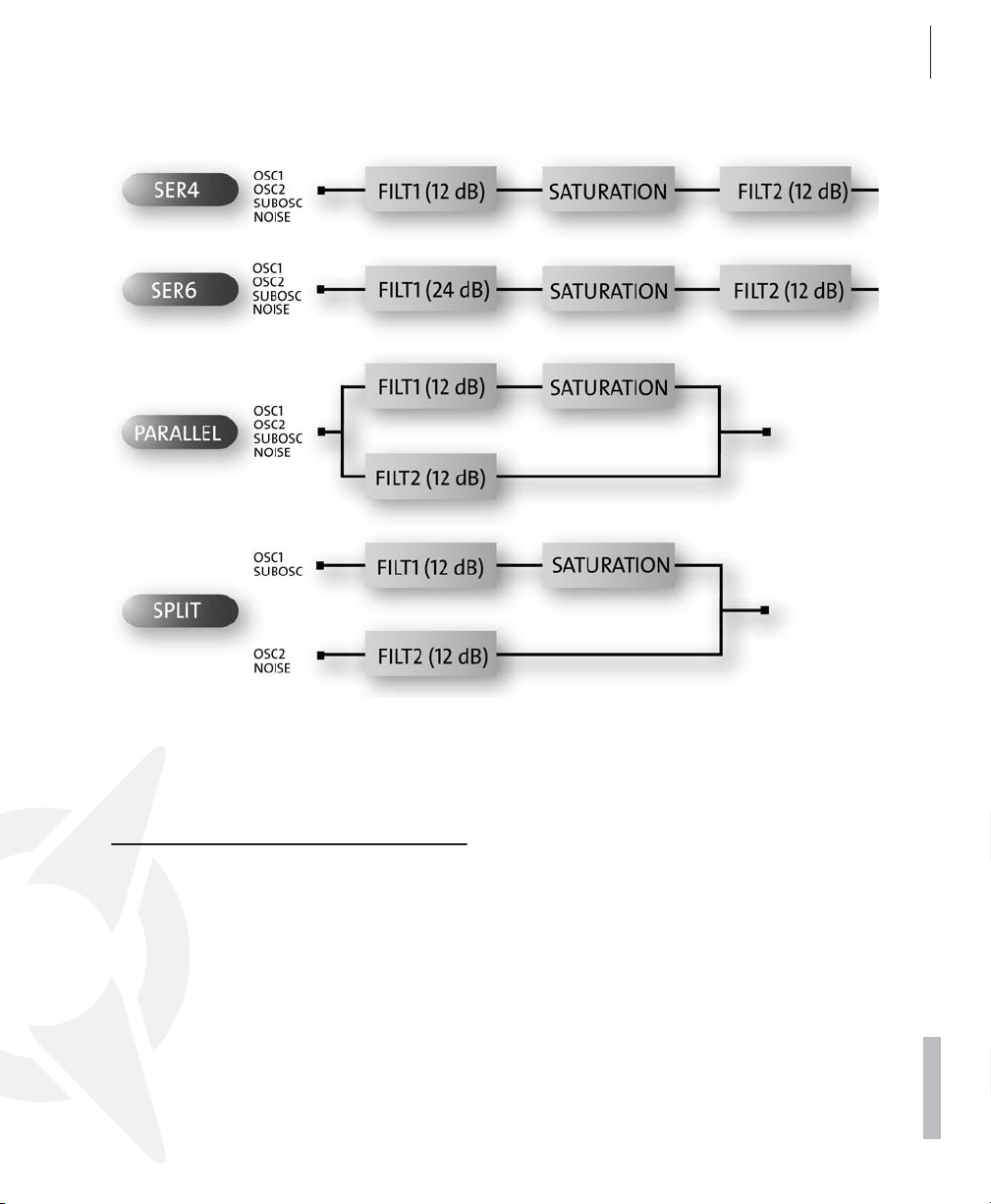
FILTER ROUTING
The final parameter we’ll discuss for the time
being is FILTER ROUTING. This feature offers
several filter routing options which allow you to
operate the filters in series, i.e. patch one after
the other in the signal chain, or in parallel, which
means side by side in the signal chain:
- SER-4 The filters are switched in series; with
two poles each (12dB/Okt.), both filters have
the same slope for a total of four filter poles
(24dB/Okt.).
- SER-6 The filters are switched in series; Fil-
ter-1 has four poles (24dB/Okt.), Filter-2 has
two poles (12dB/Okt.) so the overall slope is
equivalent to six poles (36dB/Okt.).
- PAR-4 The filters are switched in parallel and
feature two poles each (12dB/Okt.).
- SPLIT The filters are switched in parallel and
feature two poles each (12dB/Okt.). Additionally, they receive independent input signals
(more on this later). Each of the two oscillators routes its signal into one of the two filters
whose signals can be spread in the panorama
via a parameter called UNISON Pan Spread.
Regardless of which FILTER ROUTING op-
tion you chose, the SATURATION stage is always post-Filter-1, i.e. after Filter in the signal
chain.
ACCESS VIRUS OS5 25
The First Oscillator
THE FIRST OSCILLATOR
To this point, we have turned our attention exclusively to sound-shaping functions and have
always started with the same basic material: a
so-called sawtooth wave. This waveshape is
especially well-suited as a neutral starting point
as it contains all of the so-called natural scale of
overtones, which give the filter plenty of quality
material to work with.
The filters, with the exception of a notch filter or
band stop (BS), trim the far reaches of the tonal
spectrum, so for instance a signal sounds muddier after it has been routed through a low pass
filter. You can well imagine that this type of
sound modification is substantial but insufficient for shaping more subtle differences in
tone. For instance the tone of a trumpet differs
significantly from that of a saxophone even
though no one would seriously claim that either
of the instruments has a muddier tone than the
other.

26 CHAPTER 4
48
48
DETUNE 2 / 3
SHAPE
/ PW
WAVE SEL
SEMITONE
FM AMOUNT
EDIT
SYNC
SELECT
OSC 3
OSC 2
OSC 1
12
12
12
OSC 3
ON
WAVE
OSCILLATORS
AUDITION
Introduction
What you need is a sound-shaping option for
the portion of a signal that a filter allows to
pass. And of course you also need a tool for determining the pitch of a signal. In synthesizers,
both of these tasks are executed by oscillators.
They oscillate at a variable pitch that can be
modulated and they also generate different
waveshapes which give the filters a wider variety of material to work with.
The VIRUS is has two main oscillators and a socalled suboscillator. Let‘s take a look at Oscillator 1, the one you have already heard in action
during your experiments so far:
Start with the same basic sound you used at
the very beginning. Now modify the amplifier
envelope to make the sound less grating, but
hold back on any other filter or saturation modifications for the moment so you can hear the
pure, unadulterated oscillator.
Oscillator 1, the one you have already heard in
action during your experiments so far:
Start with the same basic sound you used at
the very beginning. Now modify the amplifier
envelope to make the sound less grating, but
hold back on any other filter or saturation modifications for the moment so you can hear the
pure, unadulterated oscillator.
Press the OSC 1 button in the OSCILLATORS
section to enter the edit pages for oscillator 1.
Directly above this button are the SHAPE and
WAVE SEL/PW controls which determine the
waveform and therefore the basic sound of oscillator 1. The SHAPE parameter is currently set
to the exact center (value 64), and if you look at
the panel directly above the SHAPE conrol, you
will see a symbol representing a sawtooth
wave.
OSCILLATORS
WAVE
EDIT
SHAPE
AUDITION
SYNC
0
WAVE SEL
0
FM AMOUNT
-
48
SEMITONE
OSC 1
0
48
OSC 2
SELECT
6
12
/ PW
6
12
0
DETUNE 2 / 3
OSC 3
6
OSC 3
ON
12
You can definitely see why this waveshape
bears the name “sawtooth.” Press and hold a
key and slowly turn the pot clockwise. You
should be able to hear how the tone becomes
increasingly more hollow-sounding. You might
say this effect thins the sound out, but in any
case, the entire tonal spectrum is affected by an
equal measure, which is an audio result filters
are unable to achieve.
The waveshape that is audible when you turn
the SHAPE pot to the far right is a so-called
pulse wave. The graphical representation of this
waveshape on the control panel gives you a
good idea of its appearance. It is unique because the duration of the negative pulse is
equal to the duration of the positive pulse: It has
a so-called pulse width of 50%. The tone of a
pulse wave is different to that of a sawtooth
wave because it does not contain all overtones
in the natural overtone scale, only the oddnumbered tones, i.e. the first (the root note that
determines the pitch), third, fifth, and so forth.
By turning the SHAPE pot from the sawtooth
control range towards the pulse control range,
you are actually dialing every other overtone out
of the mix, which explains why the sound becomes thinner.
You can continue modifying the sound by reducing the symmetrical width of the pulse
wave. In the VIRUS, you can execute this
sound-shaping measure via the WAVE SEL/PW

ACCESS VIRUS OS5 27
The Second Oscillator
(PW = pulse width) pot, PROVIDED THE SHAPE
POT IS SET TO A POSITION IN THE RIGHT
HALF OF ITS CONTROL RANGE (LATER THAN
12 O’CLOCK). Rotate the WAVE SEL/PW pot
slowly from the left to the right and leave the
SHAPE pot at the far right position. You can
hear how the treble content of the sound increases while the sound becomes ever thinner.
At the far right position, the signal is no longer
audible because the pulse width is equivalent to
0% and consequently the wave no longer oscillates.
Starting at the center position (12 o’clock) indicated by the sawtooth, turn the SHAPE pot
counter-clockwise towards the left. You can
hear how the overtones are increasingly mixed
out of the signal until you can only hear the root
note. This sound is produced by a so-called
sine wave, one of 64 other waveshapes that
you have at your disposal for sound generation
purposes. These waveshapes can also be activated via WAVE SEL/PW (WAVE SEL: Wave Select), PROVIDED THE SHAPE POT IS SET TO A
POSITION IN THE LEFT HALF OF ITS CONTROL RANGE (EARLIER THAN 12 O’CLOCK).
Regardless of the current SHAPE setting, you
can also select a wave in the EDIT menu under
OSCILLATOR 1 WAVE.
Go ahead and check out the different waveshapes. The second of the 64 waves is a triangle wave, the remainder of the waveshapes are
each a unique tonal blend. After you have familiarized yourself with this raw material, experiment with the parameters of the FILTERS and
AMPLIFIER sections you have dealt with thus
far (don’t forget about SATURATION and the
corresponding function of the OSC VOL pot), to
get a feel for how the diverse waveshapes respond to filtering, saturation and amplifier modifications.
THE SECOND OSCILLATOR
As already mentioned above, the Virus has a
second oscillator (as well as several other basic
sound sources which will be described later in
this manual). Press the OSC 2 button in the OSCILLATORS section to enter the edit pages for
the oscillator 2. The controls in this section now
apply to oscillator 2 only – oscillator 1 parameters cannot be changed now (although the oscillator can still be heard).
Dial in the basic sound program that you had at
the very beginning; change the amplifier envelope to suit your taste. In the sound program,
the OSC BAL (Oscillator Balance) pot in the
MIXER section is preset to the far left. In order
to hear Oscillator 2 in action, rotate the OSC
BAL (Oscillator Balance) pot in the MIXER section to the right. Towards the center position (12
o’clock) you will hear how the tone is modified
and as you rotate the pot further to the right,
how the intensity of this modification is reduced. This effect is known as the comb filtering effect. It occurs when two signals with the
same frequency but different phase lengths are
mixed. Press the same key on your keyboard
several times with the OSC BAL set to the center position (12 o’clock). You should notice that
each note has a slightly different tone. The oscillators are the source of this effect. The oscillators of the VIRUS oscillate freely,
consequently every time you play a note, the
phase constellation between the two oscillators
is different. For now, leave the OSC BAL POT at
the center position (12 o’clock).
You are already familiar with Oscillator 1’s
SHAPE and WAVE SEL/PW pots. These functions are identical for Oscillator 2, so we won’t
go into detail on them again.

28 CHAPTER 4
48
48
DETUNE 2 / 3
SHAPE
/ PW
WAVE SEL
SEMITONE
FM AMOUNT
EDIT
SYNC
SELECT
OSC 3
OSC 2
OSC 1
12
12
12
OSC 3
ON
WAVE
OSCILLATORS
AUDITION
Introduction
OSCILLATORS
6
0
DETUNE 2 / 3
OSC 3
OSC 3
WAVE
EDIT
SHAPE
AUDITION
SYNC
0
WAVE SEL
0
FM AMOUNT
-
48
SEMITONE
OSC 1
0
48
OSC 2
SELECT
6
12
/ PW
6
12
Locate the pot labeled DETUNE and slowly rotate it to the right from the far left position
(which is preset in the sound program). You can
hear the tone start to waver and as you turn the
pot further to the right, how this vibrato effect
increases until Oscillator 2 sounds distinctly out
of tune with Oscillator 1. This wavering or vibrato-type effect has a popular traditional in synthesizers. It is used to achieve chorus effects,
create sounds reminiscent of stringed instruments/ string sections or simply beef up the
sound.
The SEMITONE pot enables you to transpose
Oscillator 2 by plus/minus four octaves in semitone steps while Oscillator 1 maintains the
pitch. This feature is especially interesting when
used in conjunction with two other oscillator
functions: synchronization and frequency modulation.
Locate and activate the SYNC button in the
OSCILLATORS section (the LED must illuminate). The synchronization function forces Oscillator 2 to restart its wave cycle at the same
time as Oscillator 1 waveshape starts its cycle.
The initial effect of this measure is that the wavering tone that resulted from detuning and
mixing the oscillator signals disappears.
The SYNC effect really becomes interesting
when you transpose Oscillator 2 upwards in
comparison to Oscillator 1 via the SEMITONE
pot. What happens is that the wave cycle of Oscillator 2 is interrupted as soon as Oscillator 1
starts its cycle. The pitch of the second oscillator no longer has the expected effect, instead it
12
generates special tones, in some cases for lack
of a better description “screaming” type effects.
The other effect that benefits from manipulating
the interval between the oscillators is frequency
modulation (FM). It generates new tonal spectra
ON
in which the signal of the first oscillator controls
the frequency of the second oscillator similar to
the manner in which filters can be controlled via
envelopes. And here too you have a pot which
allows you to control the intensity of: FM
AMOUNT. Basically, this effect is similar to a vibrato, although here you’re dealing with an extremely fast vibrato featuring a frequency within
the range of human hearing. This signal is not
actually audible as a vibrato effect. Instead,
you’ll hear a sound modulation, in some cases,
a very drastic one at that. Choose the pure sine
waveshape for Oscillator 2. In conjunction with
the sine wave, the frequency modulation generates very clear, in some cases bell-like, spectra.
In the VIRUS you have the option of combining
the two functions called oscillator synchronization (SYNC) and frequency modulation (FM
AMOUNT, to generate new harmonic spectra.
Switch SYNC on and experiment with the FM
AMOUNT. Also try out different SEMITONE settings and the diverse waveshapes of Oscillator.The VIRUS is equipped with a third master
oscillator that lets you create further oscillations
and spectra. You can access the parameters of
this oscillator, which are described in a later
chapter, via the OSCILLATOR EDIT menu.
 Loading...